EP0768795A1 - Procédé pour la fabrication de pochoirs, particulièrement pour l'impression de papier ou de textiles - Google Patents
Procédé pour la fabrication de pochoirs, particulièrement pour l'impression de papier ou de textiles Download PDFInfo
- Publication number
- EP0768795A1 EP0768795A1 EP95116195A EP95116195A EP0768795A1 EP 0768795 A1 EP0768795 A1 EP 0768795A1 EP 95116195 A EP95116195 A EP 95116195A EP 95116195 A EP95116195 A EP 95116195A EP 0768795 A1 EP0768795 A1 EP 0768795A1
- Authority
- EP
- European Patent Office
- Prior art keywords
- color
- template
- bit sequence
- byte
- computer
- Prior art date
- Legal status (The legal status is an assumption and is not a legal conclusion. Google has not performed a legal analysis and makes no representation as to the accuracy of the status listed.)
- Granted
Links
- 238000000034 method Methods 0.000 title claims abstract description 20
- 238000004519 manufacturing process Methods 0.000 title claims abstract description 5
- 238000007639 printing Methods 0.000 title description 8
- 239000004753 textile Substances 0.000 title description 4
- 239000003086 colorant Substances 0.000 description 13
- 239000000976 ink Substances 0.000 description 4
- 230000033458 reproduction Effects 0.000 description 4
- 238000006243 chemical reaction Methods 0.000 description 3
- 235000019646 color tone Nutrition 0.000 description 2
- 239000004922 lacquer Substances 0.000 description 2
- 239000000203 mixture Substances 0.000 description 2
- 238000012545 processing Methods 0.000 description 2
- 230000007704 transition Effects 0.000 description 2
- 241000519995 Stachys sylvatica Species 0.000 description 1
- 230000002457 bidirectional effect Effects 0.000 description 1
- 230000015572 biosynthetic process Effects 0.000 description 1
- 238000004364 calculation method Methods 0.000 description 1
- 238000007796 conventional method Methods 0.000 description 1
- 238000013500 data storage Methods 0.000 description 1
- 238000007781 pre-processing Methods 0.000 description 1
- 238000007650 screen-printing Methods 0.000 description 1
- 238000012216 screening Methods 0.000 description 1
- 239000000758 substrate Substances 0.000 description 1
- 238000012546 transfer Methods 0.000 description 1
Images

Classifications
-
- H—ELECTRICITY
- H04—ELECTRIC COMMUNICATION TECHNIQUE
- H04N—PICTORIAL COMMUNICATION, e.g. TELEVISION
- H04N1/00—Scanning, transmission or reproduction of documents or the like, e.g. facsimile transmission; Details thereof
- H04N1/46—Colour picture communication systems
- H04N1/54—Conversion of colour picture signals to a plurality of signals some of which represent particular mixed colours, e.g. for textile printing
Definitions
- the invention relates to a method according to the preamble of claim 1.
- This method is used to produce a rotatingly stretched stencil which can be used, for example, for printing on paper or textiles.
- a rotatingly stretched stencil which can be used, for example, for printing on paper or textiles.
- it can be z.
- B. a screen printing or gravure stencil, or the like. It can consist of a hollow cylindrical rotary cylinder or a flat template element which is placed around a rotatable cylinder for processing.
- a pattern is generated by means of an engraver in the surface of the template, in that an engraving head of the engraver, which is moved relative to the template, is switched on and off by a control computer in accordance with a predetermined bit sequence.
- This bit sequence is generated from a byte sequence taken from a color file, the color file describing a pattern and being stored on a mass storage device of a server.
- the color file can e.g. B. be created by scanning an artistic template pixel by pixel, for example, optically or mechanically. But it can also be created directly on a color monitor.
- the invention has for its object the method of the aforementioned Art in such a way that the creation of the bit sequences, which are required for the engraving of the respective templates, is better coordinated with the actual work process for forming the respective templates.
- a method according to the invention for producing a rotatingly clamped template in which a pattern is generated by means of an engraver in the surface of the template, in that an engraving head of the engraver moved relative to the template is switched on and off by a control computer in accordance with a predetermined bit sequence , which is generated from a byte sequence extracted from a color file, the color file describing a pattern and being stored on a mass storage device of a server, is characterized in that the server sends the color file containing the byte sequence to another template for engraving the template and this additional computer creates the bit sequence assigned to this template.
- the central computer working as a server is now exempt from the creation of the respective bit sequences for the individual templates and it is also possible to generate the respective bit sequences from the byte sequences only when the templates are actually engraved. On the one hand, this saves operating time for the central computer or server and, on the other hand, memory area in its mass storage, since only the byte sequences containing the color files need to be stored there and not the bit sequences actually required for engraving the respective templates.
- the latter are generated by the further computer or control computer, which can be arranged directly on the engraver, and only when they are really needed.
- the corresponding byte sequences can be called up from the mass storage device of the central computer or, if they are located on removable mass storage devices are transferred by inserting the mass memory into the other computer or control computer.
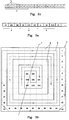
- FIG. 1a The beginning of a color file which contains an image-like motif as a stored data record is shown symbolically in FIG. 1a.
- the format shown here is the simplest format used for such a recording. In this example, one byte is used for each pixel as data storage space and this format is to be referred to as a whole-tone format.
- the pattern In order to be able to make do with such a small memory requirement per pixel, the pattern must meet the requirement that the sum of the different color tones including their intensities does not exceed the number 255. In the field of color finishing (printing) of textiles there are many patterns that this Meet requirement. This is mainly because in many color systems, e.g. B. be used for reasons of color fastness, without unsightly mixed colors. Since you have to rely on a few stencils for cost reasons, the economically processable patterns are those that only consist of 6 to 16 different colors.
- the engraver e.g. B. a laser engraver
- the engraver must receive switch-on and switch-off signals for the laser during the engraving of a template, because about one Lacquer layer must be removed from the surface of a rotary screen or hardened, which can be done in a manner known per se by a laser beam.
- a laser engraver For the purpose of fast data transfer, one will fall back on the smallest logical unit that is able to transport a switch-on or switch-off command and this is just a bit.
- FIG. 1b This format is shown in Figure 1b.
- a separate box b is used for each bit.
- a byte is then formed by eight consecutive boxes b and is identified by sections c.
- the engraving format for the template with the number 1, that is to say for the first template of the set or first color is to be generated.
- a bit may only be set, i.e. receive the value 1, if the value content of a byte of the whole-tone format (FIG. 1a) just corresponds to the number 1. Otherwise, if the value of a byte in whole tone format does not match the number (here 1) of the template to be engraved, then the bit corresponding to this byte in engraving format must be set to the value 0.
- this conversion of the byte sequence of FIG. 1 a to the bit sequence of FIG. 1 b takes place on the control computer 16 of the engraving system or on a further computer which is not identical to the computer of the CAD system preprocessing the pattern, but which is very well with this can be connected by a data network line or a bus line.
- the number of the desired color is entered into the control computer 16 or further computer via a keyboard.
- the color number obtained in this way matches the number of the template to be engraved or the template for which the engraving format is being generated, then the bit representing the data set is set to 1, otherwise to 0.
- the corresponding bit sequence is shown in FIG. 2c .
- the conversion of the halftone format (FIG. 2a) into the engraving format (FIG. 2c) according to the invention is carried out by the control computer 16 of the engraver or by another computer networked with it.
- the color palette according to FIG. 2b is stored in the control computer or further computer, and the number (eg 13) of the desired color is also entered in this.
- the comparison of the halftone format with the color component limit values of the stencil to be engraved is best carried out during the engraving - that is to say "on fly".
- the color intensities can be compared very quickly with the "on fly” screening because each data record e of the halftone format only has the 3 x 2 limit values for the color components of the template to be engraved must be compared.
- FIG. 3a A further sample description part of a color file in halftone format is shown in FIG. 3a.
- the intensity values correspond to the usual monitor intensities, that is to say they have values that lie between 0 and 255.
- a halftone template set is to be created with this file, which consists of only three templates. This set of templates must then produce mixed colors during the later printing process.
- a template is then created for one of the three color components R, G, B. Since the color intensity values do not exceed the value that can be represented by one byte, a data record e only requires 3 bytes of storage space here, namely one byte for each of the three color components R, G, B. While the red template is being engraved for each the byte describing the intensity of the red component is read out on the image point to be generated on the template. The same applies to the other color components.
- FIG. 3b shows another important piece of information for processing the data record of FIG. 3a.
- It is the gray tone reference cell of a halftone screen.
- Such reference cells can be defined in separate files. In the head of the data record in FIG. 3a there is then only an indication of the correct reference cell and the correct reference cell file.
- This gray tone reference cell here consists of 11 by 11 color or single cells g. These single cells g contain z. B. monotonously in a spiral running h to the center increasing intensity values from 1 to 255. Since there are fewer color or individual cells than intensity values in this example, the intensity values increase from cell to cell by a value 2 and after every ninth cell by a value of 3. Both the representation of the gray tone reference cell as well as that of the color or single cell is to be understood symbolically.
- the gray tone reference cell with its individual cells serves as a kind of comparison template and is only temporarily stored in the control computer 16 or further computer. It is the smallest part of the halftone screen required for a halftone rastering of the pattern data, which one would like to underlay the pattern image.
- the halftone screen is rotated in relation to the circumferential direction or the axial direction for several reasons (avoiding moiré, avoiding seams). For this reason, one must also think of the reference cell of the halftone screen rotated relative to the circumferential direction of the template to be engraved.
- the focused, grave laser beam moves over the template on a track of closely adjacent screw lines and therefore has almost the same inclination with respect to the reference cell f, which takes the circumferential direction.
- the control computer of the engraver or a further computer assigned to it uses a corresponding calculation to track both the track of the focused laser beam through the reference cell and its individual cells g and the intensity values which are to be eliminated from the halftone file (FIG. 3a) for the respective current pixel.
- the gray tone reference cell according to FIG. 3b is stored in the control computer 16 or further computer. Furthermore, They are informed (also via manual input) for which color components RG B a template is to be produced or an engraving bit sequence is to be created.
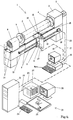
- FIG. 4 shows a laser engraver 1 known per se.
- a template 2 to be engraved is clamped on this between two support cones, the headstock support cone 4 and the tailstock support cone 7.
- the tailstock 6 is used for the rotatable mounting of the tailstock support cone 7 and the headstock 3 drives the headstock support cone 4 with the help of an invisible motor.
- An encoder 5 is used to generate pulses which correspond to the respective rotational movement of the support cone 4. 7.
- a carriage 8 is moved on guides 9 parallel to the axis of the template 2.
- a screw 10 serves to drive this carriage 8.
- a laser 11, which is mounted on the carriage 8, emits a laser beam 13, which is deflected by 90 ° through a deflecting mirror 12 and focused at 16 by a lens system 15.
- a control computer 16 is assigned to the laser engraver 1. This control computer 16 receives the sample data from the server 21 of the CAD system 22 via the data line 23. The sample data consist of the number or byte sequence for the template numbers, which has already been described several times. which may need to be combined with halftone information. The control computer 16 generates the respective bit sequence from this sample data.
- a bit in this bit sequence is given the value 1 if the corresponding pattern point is to be engraved on template 2. If the pattern point is not to be engraved, the associated bit is given the value 0.
- the stencil number is determined from a value of the number sequence and, in addition, the halftone value is also determined using the halftone conversion table according to FIG. 2b.
- the respective bit sequence is via a power converter, which is no longer shown fed to the laser 11, which is switched on or off in accordance with this bit sequence. This process creates the pattern on the template 2.
- the control computer 16 also determines when the stepper motor 18 must take a next step.
- the necessary step pulses are sent to the stepper motor 18 via the line 20 and a power amplifier, which is also no longer shown.
- the stepper motor 18 drives the screw spindle 10 and in this way moves the slide 8 with the laser 11.
- the CAD system shown here also consists of a keyboard 24, a digitizer 25 for inputting graphic data and the screen 26.
- a mass memory 27 is used for storage of image data which are transmitted to the mass storage device 27 or the server 21 via the bidirectional data line 28.
- the color files according to FIGS. 1 a, 2 a and 3 a can be temporarily stored in the mass memory 27 before they are transferred to the control computer 16 in order to create the respective image sequences according to FIGS. 1 b, 2 a and the bit sequence according to the third exemplary embodiment.
Landscapes
- Engineering & Computer Science (AREA)
- Textile Engineering (AREA)
- Multimedia (AREA)
- Signal Processing (AREA)
- Manufacture Or Reproduction Of Printing Formes (AREA)
- Printing Plates And Materials Therefor (AREA)
- Facsimiles In General (AREA)
- Facsimile Image Signal Circuits (AREA)
- Color Image Communication Systems (AREA)
- Paper (AREA)
- Coloring (AREA)
- Artificial Filaments (AREA)
Priority Applications (8)
| Application Number | Priority Date | Filing Date | Title |
|---|---|---|---|
| ES95116195T ES2142438T3 (es) | 1995-10-13 | 1995-10-13 | Procedimiento para confeccionar una plantilla, especialmene para imprimir sobre papel o tejidos. |
| EP95116195A EP0768795B1 (fr) | 1995-10-13 | 1995-10-13 | Procédé pour la fabrication de pochoirs, particulièrement pour l'impression de papier ou de textiles |
| DE59507532T DE59507532D1 (de) | 1995-10-13 | 1995-10-13 | Verfahren zur Herstellung einer Schablone, insbesondere für den Papier- oder Textildruck |
| AT95116195T ATE188323T1 (de) | 1995-10-13 | 1995-10-13 | Verfahren zur herstellung einer schablone, insbesondere für den papier- oder textildruck |
| AU64393/96A AU6439396A (en) | 1995-10-13 | 1996-08-30 | Method of producing a stencil, especially for printing paper or textiles |
| US08/729,412 US5822209A (en) | 1995-10-13 | 1996-10-11 | Method and system for producing a stencil by storing color files and creating the needed bit sequence |
| JP08270771A JP3078753B2 (ja) | 1995-10-13 | 1996-10-14 | ステンシル製造システム |
| CN96120318A CN1108925C (zh) | 1995-10-13 | 1996-10-14 | 用于印刷纸张或织物的模板的制造方法 |
Applications Claiming Priority (1)
| Application Number | Priority Date | Filing Date | Title |
|---|---|---|---|
| EP95116195A EP0768795B1 (fr) | 1995-10-13 | 1995-10-13 | Procédé pour la fabrication de pochoirs, particulièrement pour l'impression de papier ou de textiles |
Publications (2)
| Publication Number | Publication Date |
|---|---|
| EP0768795A1 true EP0768795A1 (fr) | 1997-04-16 |
| EP0768795B1 EP0768795B1 (fr) | 1999-12-29 |
Family
ID=8219716
Family Applications (1)
| Application Number | Title | Priority Date | Filing Date |
|---|---|---|---|
| EP95116195A Expired - Lifetime EP0768795B1 (fr) | 1995-10-13 | 1995-10-13 | Procédé pour la fabrication de pochoirs, particulièrement pour l'impression de papier ou de textiles |
Country Status (8)
| Country | Link |
|---|---|
| US (1) | US5822209A (fr) |
| EP (1) | EP0768795B1 (fr) |
| JP (1) | JP3078753B2 (fr) |
| CN (1) | CN1108925C (fr) |
| AT (1) | ATE188323T1 (fr) |
| AU (1) | AU6439396A (fr) |
| DE (1) | DE59507532D1 (fr) |
| ES (1) | ES2142438T3 (fr) |
Families Citing this family (8)
| Publication number | Priority date | Publication date | Assignee | Title |
|---|---|---|---|---|
| US6385499B1 (en) * | 1998-08-25 | 2002-05-07 | Cold Spring Granite Company | Method for preparing memorial products, apparatus for preparing memorial products, and memorial product |
| GB9923795D0 (en) * | 1999-10-09 | 1999-12-08 | British Aerospace | Micropositioning system |
| US20020119399A1 (en) * | 2001-02-26 | 2002-08-29 | Leskanic Jesse E. | Laser fabrication of rotary printing screens |
| DE102004036662B3 (de) * | 2004-07-28 | 2006-05-04 | Lpkf Laser & Electronics Ag | Verfahren zum Einringen von Durchbrechungen in eine Schablone oder Maske |
| US20060130679A1 (en) * | 2004-12-20 | 2006-06-22 | Dubois Radford E Iii | Automated cutting system for customized field stencils |
| US7894924B2 (en) * | 2006-11-09 | 2011-02-22 | Matthews Resources, Inc. | System and method for internet based automated memorial design and manufacturing |
| US8563892B2 (en) * | 2008-09-24 | 2013-10-22 | Standex International Corporation | Method and apparatus for laser engraving |
| US10332173B2 (en) | 2013-08-27 | 2019-06-25 | Matthews International Corporation | Systems, methods, and computer-readable media for generating a memorial product |
Citations (6)
| Publication number | Priority date | Publication date | Assignee | Title |
|---|---|---|---|---|
| FR2136475A5 (fr) * | 1971-04-17 | 1972-12-22 | Morat Gmbh Franz | |
| US4507685A (en) * | 1982-06-25 | 1985-03-26 | Canon Kabushiki Kaisha | Image recording device |
| GB2199462A (en) * | 1986-12-24 | 1988-07-06 | Textima Veb K | Pattern preparation for coloured pattern textile production |
| EP0293214A2 (fr) * | 1987-05-29 | 1988-11-30 | Digital Equipment Corporation | Système produisant des images en demi-teintes selon des grilles asymétriques |
| FR2645073A1 (fr) * | 1989-03-30 | 1990-10-05 | Gravit Sa | Procede et dispositif de fabrication d'un masque de gravure pour l'impression sur textiles |
| EP0612181A1 (fr) * | 1993-02-19 | 1994-08-24 | Linotype-Hell Ag | Procédé et appareil pour la conversion de valeurs de gris en valeurs binaires |
Family Cites Families (5)
| Publication number | Priority date | Publication date | Assignee | Title |
|---|---|---|---|---|
| FR2608797B1 (fr) * | 1986-12-23 | 1989-04-28 | Cauwet Claude | Perfectionnements aux procedes de gravure automatique |
| CN1022417C (zh) * | 1990-06-04 | 1993-10-13 | 中国科学院长春应用化学研究所 | 速溶阴离子型聚丙烯酰胺制备 |
| IT1246734B (it) * | 1990-12-24 | 1994-11-26 | Ms Servizi Informatici | Apparecchiatura elettronica per l'incisione mediante raggio laser di quadri da stampa serigrafica e simili. |
| CN1069694A (zh) * | 1992-05-23 | 1993-03-10 | 秦剑平 | 丝印模版的制作方法 |
| ES2102094T3 (es) * | 1994-04-26 | 1997-07-16 | Schablonentechnik Kufstein Ag | Procedimiento y dispositivo para la fabricacion de una plantilla de serigrafia. |
-
1995
- 1995-10-13 EP EP95116195A patent/EP0768795B1/fr not_active Expired - Lifetime
- 1995-10-13 AT AT95116195T patent/ATE188323T1/de not_active IP Right Cessation
- 1995-10-13 DE DE59507532T patent/DE59507532D1/de not_active Expired - Fee Related
- 1995-10-13 ES ES95116195T patent/ES2142438T3/es not_active Expired - Lifetime
-
1996
- 1996-08-30 AU AU64393/96A patent/AU6439396A/en not_active Abandoned
- 1996-10-11 US US08/729,412 patent/US5822209A/en not_active Expired - Fee Related
- 1996-10-14 CN CN96120318A patent/CN1108925C/zh not_active Expired - Fee Related
- 1996-10-14 JP JP08270771A patent/JP3078753B2/ja not_active Expired - Fee Related
Patent Citations (6)
| Publication number | Priority date | Publication date | Assignee | Title |
|---|---|---|---|---|
| FR2136475A5 (fr) * | 1971-04-17 | 1972-12-22 | Morat Gmbh Franz | |
| US4507685A (en) * | 1982-06-25 | 1985-03-26 | Canon Kabushiki Kaisha | Image recording device |
| GB2199462A (en) * | 1986-12-24 | 1988-07-06 | Textima Veb K | Pattern preparation for coloured pattern textile production |
| EP0293214A2 (fr) * | 1987-05-29 | 1988-11-30 | Digital Equipment Corporation | Système produisant des images en demi-teintes selon des grilles asymétriques |
| FR2645073A1 (fr) * | 1989-03-30 | 1990-10-05 | Gravit Sa | Procede et dispositif de fabrication d'un masque de gravure pour l'impression sur textiles |
| EP0612181A1 (fr) * | 1993-02-19 | 1994-08-24 | Linotype-Hell Ag | Procédé et appareil pour la conversion de valeurs de gris en valeurs binaires |
Also Published As
| Publication number | Publication date |
|---|---|
| ATE188323T1 (de) | 2000-01-15 |
| CN1108925C (zh) | 2003-05-21 |
| JPH09109357A (ja) | 1997-04-28 |
| AU6439396A (en) | 1997-04-17 |
| DE59507532D1 (de) | 2000-02-03 |
| CN1151939A (zh) | 1997-06-18 |
| ES2142438T3 (es) | 2000-04-16 |
| JP3078753B2 (ja) | 2000-08-21 |
| EP0768795B1 (fr) | 1999-12-29 |
| US5822209A (en) | 1998-10-13 |
Similar Documents
| Publication | Publication Date | Title |
|---|---|---|
| DE2321689C3 (de) | Farbscanner | |
| DE2018317C3 (de) | Verfahren zur Farbreproduktion von farbigen Vorlagen, bei dem die Vorlage punktweise abgetastet wird | |
| DE2637055C2 (de) | Farbkorrekturanordnung für Reproduktionszwecke | |
| DE2060661C3 (de) | Verfahren zum Herstellen einer Fläche in Form eines Reliefs sowie Vorrichtung zur Durchführung des Verfahrens | |
| DE69629279T2 (de) | Verfahren und vorrichtung zum gravieren | |
| EP0074422B1 (fr) | Procédé pour la production de planches au moyen de points d'impression à distribution irrégulière | |
| DE3036711C2 (de) | Verfahren zum Verkleinern von grafischen Mustern | |
| DE2729113A1 (de) | Bildreproduktionsverfahren zur herstellung eines ganzseitigen bildes | |
| EP0141869A1 (fr) | Procédé et appareil pour la fabrication de formes d'impression tramées | |
| DE19631469C1 (de) | Verfahren und Vorrichtung zur Durchführung von Druckaufträgen | |
| EP0032908B1 (fr) | Procede d'analyse autotypique de valeurs de tonalite | |
| DE3345306A1 (de) | Verfahren und vorrichtung zur verarbeitung von bilddaten | |
| EP0243523B1 (fr) | Procédé pour l'enregistrement de formes d'impression | |
| DE2161038B2 (de) | Verfahren zur Herstellung von gerasterten Druckformen | |
| DE2012728C3 (de) | Verfahren zur elektrooptischen Aufzeichnung von gerasterten Halbtonbildern | |
| DE3511705C2 (fr) | ||
| EP0011722A2 (fr) | Procédé et dispositif de réglage digital pour obtenir des reproductions en couleurs | |
| WO1984004974A1 (fr) | Procede de reproduction pour produire des impressions polychromes | |
| EP0768795B1 (fr) | Procédé pour la fabrication de pochoirs, particulièrement pour l'impression de papier ou de textiles | |
| DE3129649C2 (fr) | ||
| DE3443174A1 (de) | Verfahren zum scannen und aufzeichnen eines bilds | |
| EP0612181A1 (fr) | Procédé et appareil pour la conversion de valeurs de gris en valeurs binaires | |
| DE3601269C2 (fr) | ||
| DE69125958T2 (de) | Druckplatte | |
| DE2147398A1 (de) | Vorrichtung zum Reproduzieren graphischen Materials |
Legal Events
| Date | Code | Title | Description |
|---|---|---|---|
| PUAI | Public reference made under article 153(3) epc to a published international application that has entered the european phase |
Free format text: ORIGINAL CODE: 0009012 |
|
| 17P | Request for examination filed |
Effective date: 19960626 |
|
| AK | Designated contracting states |
Kind code of ref document: A1 Designated state(s): AT CH DE ES FR GB IT LI NL |
|
| 17Q | First examination report despatched |
Effective date: 19980618 |
|
| GRAG | Despatch of communication of intention to grant |
Free format text: ORIGINAL CODE: EPIDOS AGRA |
|
| GRAG | Despatch of communication of intention to grant |
Free format text: ORIGINAL CODE: EPIDOS AGRA |
|
| GRAH | Despatch of communication of intention to grant a patent |
Free format text: ORIGINAL CODE: EPIDOS IGRA |
|
| GRAH | Despatch of communication of intention to grant a patent |
Free format text: ORIGINAL CODE: EPIDOS IGRA |
|
| GRAA | (expected) grant |
Free format text: ORIGINAL CODE: 0009210 |
|
| AK | Designated contracting states |
Kind code of ref document: B1 Designated state(s): AT CH DE ES FR GB IT LI NL |
|
| REF | Corresponds to: |
Ref document number: 188323 Country of ref document: AT Date of ref document: 20000115 Kind code of ref document: T |
|
| REG | Reference to a national code |
Ref country code: CH Ref legal event code: EP |
|
| REG | Reference to a national code |
Ref country code: CH Ref legal event code: NV Representative=s name: A. BRAUN, BRAUN, HERITIER, ESCHMANN AG PATENTANWAE |
|
| GBT | Gb: translation of ep patent filed (gb section 77(6)(a)/1977) |
Effective date: 19991229 |
|
| ET | Fr: translation filed | ||
| REF | Corresponds to: |
Ref document number: 59507532 Country of ref document: DE Date of ref document: 20000203 |
|
| ITF | It: translation for a ep patent filed | ||
| REG | Reference to a national code |
Ref country code: ES Ref legal event code: FG2A Ref document number: 2142438 Country of ref document: ES Kind code of ref document: T3 |
|
| PLBE | No opposition filed within time limit |
Free format text: ORIGINAL CODE: 0009261 |
|
| STAA | Information on the status of an ep patent application or granted ep patent |
Free format text: STATUS: NO OPPOSITION FILED WITHIN TIME LIMIT |
|
| 26N | No opposition filed | ||
| REG | Reference to a national code |
Ref country code: GB Ref legal event code: IF02 |
|
| PGFP | Annual fee paid to national office [announced via postgrant information from national office to epo] |
Ref country code: ES Payment date: 20021010 Year of fee payment: 8 |
|
| PGFP | Annual fee paid to national office [announced via postgrant information from national office to epo] |
Ref country code: GB Payment date: 20021016 Year of fee payment: 8 |
|
| PGFP | Annual fee paid to national office [announced via postgrant information from national office to epo] |
Ref country code: CH Payment date: 20021023 Year of fee payment: 8 Ref country code: AT Payment date: 20021023 Year of fee payment: 8 |
|
| PGFP | Annual fee paid to national office [announced via postgrant information from national office to epo] |
Ref country code: DE Payment date: 20021025 Year of fee payment: 8 |
|
| PGFP | Annual fee paid to national office [announced via postgrant information from national office to epo] |
Ref country code: FR Payment date: 20021028 Year of fee payment: 8 |
|
| PGFP | Annual fee paid to national office [announced via postgrant information from national office to epo] |
Ref country code: NL Payment date: 20021031 Year of fee payment: 8 |
|
| PG25 | Lapsed in a contracting state [announced via postgrant information from national office to epo] |
Ref country code: GB Free format text: LAPSE BECAUSE OF NON-PAYMENT OF DUE FEES Effective date: 20031013 Ref country code: AT Free format text: LAPSE BECAUSE OF NON-PAYMENT OF DUE FEES Effective date: 20031013 |
|
| PG25 | Lapsed in a contracting state [announced via postgrant information from national office to epo] |
Ref country code: ES Free format text: LAPSE BECAUSE OF NON-PAYMENT OF DUE FEES Effective date: 20031014 |
|
| PG25 | Lapsed in a contracting state [announced via postgrant information from national office to epo] |
Ref country code: LI Free format text: LAPSE BECAUSE OF NON-PAYMENT OF DUE FEES Effective date: 20031031 Ref country code: CH Free format text: LAPSE BECAUSE OF NON-PAYMENT OF DUE FEES Effective date: 20031031 |
|
| PG25 | Lapsed in a contracting state [announced via postgrant information from national office to epo] |
Ref country code: NL Free format text: LAPSE BECAUSE OF NON-PAYMENT OF DUE FEES Effective date: 20040501 Ref country code: DE Free format text: LAPSE BECAUSE OF NON-PAYMENT OF DUE FEES Effective date: 20040501 |
|
| GBPC | Gb: european patent ceased through non-payment of renewal fee |
Effective date: 20031013 |
|
| REG | Reference to a national code |
Ref country code: CH Ref legal event code: PL |
|
| PG25 | Lapsed in a contracting state [announced via postgrant information from national office to epo] |
Ref country code: FR Free format text: LAPSE BECAUSE OF NON-PAYMENT OF DUE FEES Effective date: 20040630 |
|
| NLV4 | Nl: lapsed or anulled due to non-payment of the annual fee |
Effective date: 20040501 |
|
| REG | Reference to a national code |
Ref country code: FR Ref legal event code: ST |
|
| REG | Reference to a national code |
Ref country code: ES Ref legal event code: FD2A Effective date: 20031014 |
|
| PG25 | Lapsed in a contracting state [announced via postgrant information from national office to epo] |
Ref country code: IT Free format text: LAPSE BECAUSE OF NON-PAYMENT OF DUE FEES Effective date: 20051013 |