EP0769335A1 - Gerät zur Neugestaltung der Rollen beim Formen von gewalztem Stahl - Google Patents
Gerät zur Neugestaltung der Rollen beim Formen von gewalztem Stahl Download PDFInfo
- Publication number
- EP0769335A1 EP0769335A1 EP96306984A EP96306984A EP0769335A1 EP 0769335 A1 EP0769335 A1 EP 0769335A1 EP 96306984 A EP96306984 A EP 96306984A EP 96306984 A EP96306984 A EP 96306984A EP 0769335 A1 EP0769335 A1 EP 0769335A1
- Authority
- EP
- European Patent Office
- Prior art keywords
- sleeve
- spindle
- nut ring
- straightening
- straightener
- Prior art date
- Legal status (The legal status is an assumption and is not a legal conclusion. Google has not performed a legal analysis and makes no representation as to the accuracy of the status listed.)
- Granted
Links
- 229910000831 Steel Inorganic materials 0.000 title description 4
- 239000010959 steel Substances 0.000 title description 4
- 238000002407 reforming Methods 0.000 title 1
- 238000007493 shaping process Methods 0.000 title 1
- 230000007246 mechanism Effects 0.000 claims abstract description 10
- 230000002093 peripheral effect Effects 0.000 claims description 4
- 230000008859 change Effects 0.000 description 6
- 238000005096 rolling process Methods 0.000 description 4
- 238000005452 bending Methods 0.000 description 2
- 238000001816 cooling Methods 0.000 description 2
- 125000006850 spacer group Chemical group 0.000 description 2
- 230000009471 action Effects 0.000 description 1
- 230000008602 contraction Effects 0.000 description 1
- 230000003111 delayed effect Effects 0.000 description 1
- 238000005516 engineering process Methods 0.000 description 1
- 238000003780 insertion Methods 0.000 description 1
- 230000037431 insertion Effects 0.000 description 1
- 238000012423 maintenance Methods 0.000 description 1
- 239000000463 material Substances 0.000 description 1
- 238000000034 method Methods 0.000 description 1
- 238000003825 pressing Methods 0.000 description 1
- 230000008569 process Effects 0.000 description 1
- 230000008707 rearrangement Effects 0.000 description 1
Images




Classifications
-
- B—PERFORMING OPERATIONS; TRANSPORTING
- B21—MECHANICAL METAL-WORKING WITHOUT ESSENTIALLY REMOVING MATERIAL; PUNCHING METAL
- B21B—ROLLING OF METAL
- B21B31/00—Rolling stand structures; Mounting, adjusting, or interchanging rolls, roll mountings, or stand frames
-
- B—PERFORMING OPERATIONS; TRANSPORTING
- B21—MECHANICAL METAL-WORKING WITHOUT ESSENTIALLY REMOVING MATERIAL; PUNCHING METAL
- B21D—WORKING OR PROCESSING OF SHEET METAL OR METAL TUBES, RODS OR PROFILES WITHOUT ESSENTIALLY REMOVING MATERIAL; PUNCHING METAL
- B21D3/00—Straightening or restoring form of metal rods, metal tubes, metal profiles, or specific articles made therefrom, whether or not in combination with sheet metal parts
- B21D3/02—Straightening or restoring form of metal rods, metal tubes, metal profiles, or specific articles made therefrom, whether or not in combination with sheet metal parts by rollers
- B21D3/05—Straightening or restoring form of metal rods, metal tubes, metal profiles, or specific articles made therefrom, whether or not in combination with sheet metal parts by rollers arranged on axes rectangular to the path of the work
-
- B—PERFORMING OPERATIONS; TRANSPORTING
- B21—MECHANICAL METAL-WORKING WITHOUT ESSENTIALLY REMOVING MATERIAL; PUNCHING METAL
- B21B—ROLLING OF METAL
- B21B27/00—Rolls, roll alloys or roll fabrication; Lubricating, cooling or heating rolls while in use
- B21B27/02—Shape or construction of rolls
- B21B27/028—Variable-width rolls
Definitions
- the present invention relates to a roller straightener having a straightening roller width changing device for straightening the warp of sections represented by wide flange beams.
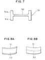
- a hot rolled and molded wide flange beam will have a temperature difference in a flange upper portion 51a as compared to a flange lower portion 51b and at right and left flanges due to the difference of cooling conditions at the upper and lower sides and the right and left sides of the beam.
- a difference in an amount of thermal contraction is created in the cooling process after the completion of rolling and deformation.
- a curve (FIG. 8(a)) and a warp (FIG. 8(b)) is formed in the wide flange beam when it is cooled down to room temperature.
- deformation such as curve and warp is sometimes caused by the asymmetrical rolling in a right to left portion and an upper to lower portion due to a slight amount of difference in a roll peripheral speed and the like in a rolling process. Since a deformed wide flange beam has no commodity value, it must be straightened. In general, a wide flange beam is straightened by being passed through straightening rolls 5 disposed as shown in FIG 9. As shown in FIG. 10, a roller straightener straightens the deformation of a wide flange beam in such a manner that bending deformation is repeatedly applied to the wide flange beam in the lengthwise direction thereof.
- the bending deformation action is gradually reduced while causing the inner surface of the flanges 51 of the wide flange beam to be abutted against the sides of the straightening rolls 5 or by providing a slight gap therebetween as well as rolling down a web 52 by the outer peripheral surfaces of the straightening rolls 5.
- a roller straightener which is driven and not driven during straightening. For example, although a straightening roll is driven on the upper side of a wide flange beam in FIG. 8, a straightening roll is not generally driven on the lower side thereof.
- the roller straightener includes a sleeve 3 having a pair of straightening rolls 5 being of a size corresponding to the size of the wide flange beam 1 and a spacer 45 set thereto and fitted to the outside of a spindle 2.
- a key 4 fixes the sleeve 3 to the spindle 2.
- Japanese Patent Unexamined Publication No. 5-328 proposes a hydraulic operation type roller width change system for permitting the change of a straightening roller width online.
- the hydraulic operation system has so many problems in maintenance, that a hydraulic pressure must be supplied to a rotation spindle and it is difficult to perfectly seal the hydraulic pressure supply passage between the fixed portion and the rotating portion of the spindle, and the like.
- the size of a pressurizing cylinder must be increased because the positions of the straightening rolls must be maintained against a thrust force applied from the piece being straightened.
- Japanese Patent Unexamined Publication No. 53-40674 disclose technologies for changing a straightening roller width online, all of them require the addition of large equipment such as a drive unit for changing the roller width. Therefore, they do not satisfy the object of the present invention.
- An object of the present invention is to provide a roller width changeable type roller straightener of a simple structure that is capable of solving the above problems and easily changing the straightening roller width of a roller straightener for straightening the warp of sections online by a remote operation.
- the present invention developed to solve the above problems is a roller straightener having a mechanism for changing a straightening roller width using the rotational force of a spindle as a drive force.
- a first example of this structure has an open sided roller width changeable type roller straightener.
- a straightening roll among a pair of straightening rolls mounted to a sleeve attached to a spindle is fixed to the sleeve.
- the other straightening roll is made slidable with respect to the spindle.
- a straightening roller width can be changed online by a remote operation.
- a nut ring meshed with the screw portion of a slidable straightening roll base is rotatably mounted to the sleeve.
- a nut ring fixing device is positioned on the spindle and a nut ring detent is in relation to a straightener main body. Both the straightening rolls and the nut ring are fixed to a spindle and rotate together with it during straightening. The nut ring is fixed by a detent so that it is not rotated while a straightening roller width is to be changed, and then the roller width is changed by the rotation of the spindle.
- a first structure of the present invention is an open sided roller straightener having a straightening roller width changing device for straightening the warp of wide flange beams arranged such that the straightening roll on one side of a pair of straightening rolls fitted onto the outside of the sleeve attached to a spindle, is fixed to a cylindrical base fitted to the sleeve, so as to be movable in contact with the outer periphery of the sleeve.
- Male threads are disposed in relation to the outer periphery of the base.
- a nut ring having female threads is meshed with the male threads.
- the nut ring is meshed with the screw portion of the cylindrical base, and a nut ring fixing pin is mounted on the spindle to which the sleeve is inserted and the detent of the nut ring is disposed to a straightener main body.
- a second structure of the present invention is a double supported roller straightener having a straightening roller width changing device for straightening the warp of wide flange beams arranged such that one of a pair of straightening rolls fitted onto the outside of the sleeve attached to a spindle is fixed to a cylindrical base fitted to the sleeve so as to be movable in contact with the outer periphery of the sleeve.
- Male threads are disposed in relation to the outer peripheral portion of the base, and a nut ring having female threads is meshed with the male threads.
- the nut ring is rotatable with respect to the cylindrical base, and an internal gear is disposed to be commonly meshed with a nut ring detent external gear fixed to the sleeve and an external gear mounted to a nut ring holding portion.
- a detent release device is mounted to a straightener main body to permit the internal gear to be meshed with and released from the external gear.
- roller straightener of the present invention is applicable the straightening of almost all types of rolled sections.
- a fixed straightening roll, a moving straightening roll, a nut ring, a nut ring fixing mechanism and a nut ring release mechanism with a sleeve and the structure of a straightener can be greatly simplified, when rolled sections (for example, steel sheet piles) other than wide flanged beams are to be straightened, the straightening rolls (sleeve) can be easily replaced. Further, since no special drive unit is needed to change a roller width, the apparatus can be simplified.
- FIG. 1 is a cross sectional view showing the first embodiment of the present invention where a wide flanged beam 1 is being straightened by an open sided roller straightener.
- a sleeve 3 is fitted onto the outer periphery of a spindle 2 and the rotational direction of the sleeve 3 is fixed to that of the spindle 2 by a key 4.
- a fixed straightening roll 5a and a moving straightening roll 5b are fitted to the outside of the sleeve 3 and the moving straightening roll 5b is fixed to a base 6 having a male screw 6a.
- a key 7 prevents the rotation of the fixed straightening roll 5a and the base 6 with respect to the sleeve 3.
- a nut ring 9 is rotatably mounted to the sleeve 3 through a bearing 8. The female threads of the nut ring 9 engage the male screw 6a of the base 6.
- the holer 10 of a nut ring fixing pin 11 presses the fixing pin 11 against the nut ring 9 through a spring 22.
- a key 12 fixes the holder 10 to the spindle 2.
- a cylinder 13 is a cylindrical-shaped cylinder mounted to a main body 14 and an arm 15 is an arm for releasing the nut ring fixing pin 11 and has a roll 16 mounted at its extreme end.
- a nut ring detent 17 is rotatably mounted to a bracket 18 and is fitted into a groove 9a formed on the outer periphery of the nut ring 9 by being rotated 90° by a not shown cylinder or the like so as to be able to keep the nut ring 9 in an unrotational state as shown in FIG. 2.
- the spindle 2 is supported by bearings 19, 20.
- the bracket 18 is fixed to the main body frame 14.
- FIG. 2 is a cross sectional view showing a roller width being changed, wherein the cylinder 13 is actuated to move the fixing pin 11 to the main body frame 14 by the arm 15 so that the nut ring 9 is in a rotatable state with respect to the spindle 2 and the sleeve 3. Further, the nut ring detent 17 is rotated 90° by a not shown cylinder or the like and is inserted into the groove 9a of the nut ring 9 to thereby prevent the rotation of the nut ring 9. The nut ring 9 is fixed to the main body frame 14 through the nut ring detent 17 and the bracket 18.
- the male threads 6a threaded to the female threads 9b are rotated by rotating the spindle 2 by a main drive motor or an auxiliary drive motor to thereby move the moving roll 5b in the longitudinal direction of the spindle.
- the amount of movement can be controlled by the screw pitch of the base 6 of the moving roll 5b and the amount of rotation of the spindle 2.
- the distance between the fixed roll 5a and the moving roll 5b can be arbitrarily changed.
- the roller width of the roller straightener for rolled sections can be very easily changed.
- FIG. 4 is a cross sectional view showing a second embodiment of the present invention in which shown is the state where a wide flanged beam 1 is being straightened by a double supported roller straightener.
- a sleeve 3 is fitted onto the outer periphery of a spindle 2 and the rotational direction of sleeve 3 is fixed to that of the spindle 2 by a key 4.
- a fixed straightening roll 5a and a moving straightening roll 5b are fitted to the outside of the sleeve 3 and the moving roll 5b is fixed to a cylindrical base 6.
- a key 7 prevents the rotation of the fixed roll 5a and the base 6 with respect to the sleeve 3.
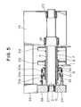
- a nut ring 9 engages a threaded portion on the outer periphery of the cylindrical base 6 and is fixed to a nut ring holder 30.
- a ring-shaped internal gear 31 pressed against the left by a spring 30a is slidably mounted to the outside surface of the nut ring holder 30 and an external gear 32a fixed to the nut ring holder 30 is meshed therewith.
- a slide ring 33 is mounted to the inside surface of the nut ring holder 30 and rotatably held by a nut ring detent 34 fixed to the sleeve 3.
- An external gear 32b is mounted on the nut ring detent 34 and meshed with the internal gear 31 during straightening to thereby rotate the nut ring holder 30 together with the spindle 2 to prevent the change of a width.
- Drive side bearings 19, 20 are supported by a drive side frame 14.
- a non-drive side bearing 37 and a non-drive side chock 38 are supported by a non-drive side frame 39 and function to rise up and fall down by a not shown lift device when straightening rolls are replaced.
- FIG. 5 is a cross sectional view showing the roller width of the straightener being changed.
- FIG. 6 is a cross sectional view showing the straightening being carried out on an upper half portion and a roller width being changed on a lower half portion.
- the external gear 32b engaged with the nut ring detent 34 and with the internal gear 31 is released therefrom by pressing a detent release device 41 against the internal gear 31 (refer to the lower half portion of FIG. 6) by actuating a cylinder 40 mounted to the non-drive side chock 38 (FIG. 6).
- a nut ring rotation restricting pin 42 is mounted at the extreme end of the detent release device 41 and the rotation of the nut ring 9 is stopped by the insertion of the pin 42 into the internal gear 31.
- the spindle 2 is rotated by a main drive motor or an auxiliary drive motor in this case to move the cylindrical base 6 a predetermined amount.
- the cylindrical base can be controlled by screw pitch and the amount of rotation of the spindle.
- a sensor 44 detects that the internal gear 31 is meshed with the external gear 32a and the nut ring is fixed to the sleeve.
- the straightening roller width of the roller straightener for wide flange beams can be easily changed online.
- the present invention is not limited to the combination of the parts such as the gears and the like described in the above embodiments but may be any comparable mechanism so long as the it permits rolls to be horizontally moved by the rotation of a spindle.
- any type of the open sided roller straightener and double supported roller straightener may be employed.
- roller straightener for wide flanged beams, since a straightening roller width can be adjusted online by a remote operation by the disposition of the nut mechanism to the sleeve to which the straightening rolls are set, a roll rearrangement can be eliminated, whereby productivity can be greatly improved. Further, since the mechanism is simplified, an amount of investment in plant and machinery can be greatly reduced.
- the present invention is also applicable to a straightener of a conventional system.
- the straightener can be adapted to simple mechanisms by mounting certain accessory members such as the fixed straightening roll, the sliding straightening roll, the nut ring and the like to the sleeve. Further, since it suffices only to mount the nut ring fixing device and the detent to the spindle and the main body, and since no special drive unit is needed to change the straightening roller width, the equipment is adapted simply as a unit and a conventional roller straightener can be remodeled by merely replacing certain accessory members such as the spindle, the sleeve and the like.
Landscapes
- Engineering & Computer Science (AREA)
- Mechanical Engineering (AREA)
- Straightening Metal Sheet-Like Bodies (AREA)
- Reduction Rolling/Reduction Stand/Operation Of Reduction Machine (AREA)
Applications Claiming Priority (6)
| Application Number | Priority Date | Filing Date | Title |
|---|---|---|---|
| JP25366595 | 1995-09-29 | ||
| JP253665/95 | 1995-09-29 | ||
| JP25366595 | 1995-09-29 | ||
| JP01568496A JP3288215B2 (ja) | 1995-09-29 | 1996-01-31 | 形鋼用ローラ矯正機の幅可変装置 |
| JP1568496 | 1996-01-31 | ||
| JP15684/96 | 1996-01-31 |
Publications (2)
| Publication Number | Publication Date |
|---|---|
| EP0769335A1 true EP0769335A1 (de) | 1997-04-23 |
| EP0769335B1 EP0769335B1 (de) | 2002-05-22 |
Family
ID=26351872
Family Applications (1)
| Application Number | Title | Priority Date | Filing Date |
|---|---|---|---|
| EP96306984A Expired - Lifetime EP0769335B1 (de) | 1995-09-29 | 1996-09-25 | Gerät zur Neugestaltung der Rollen beim Formen von gewalztem Stahl |
Country Status (5)
| Country | Link |
|---|---|
| US (1) | US5826455A (de) |
| EP (1) | EP0769335B1 (de) |
| JP (1) | JP3288215B2 (de) |
| KR (1) | KR100405225B1 (de) |
| DE (1) | DE69621303T2 (de) |
Cited By (3)
| Publication number | Priority date | Publication date | Assignee | Title |
|---|---|---|---|---|
| CN102151721A (zh) * | 2010-12-27 | 2011-08-17 | 綦江永跃齿轮有限公司 | 内齿圈校直架 |
| CN105414394A (zh) * | 2015-11-02 | 2016-03-23 | 扬中市三环电热科技有限公司 | 一种双靠轮绕丝机用双靠轮 |
| WO2023138888A1 (de) * | 2022-01-24 | 2023-07-27 | Sms Group Gmbh | Richtmaschine sowie verfahren zum richten eines stahlprofils |
Families Citing this family (3)
| Publication number | Priority date | Publication date | Assignee | Title |
|---|---|---|---|---|
| JP6342365B2 (ja) * | 2015-06-24 | 2018-06-13 | 三菱重工業株式会社 | ロール成形装置 |
| CN108500098A (zh) * | 2018-04-24 | 2018-09-07 | 安徽知之信息科技有限公司 | 一种新能源汽车用扭杆弹簧的预扭防弯矩装置 |
| CN112808798A (zh) * | 2020-11-30 | 2021-05-18 | 中冶华天工程技术有限公司 | 成排矫直机矫直组合辊系 |
Citations (4)
| Publication number | Priority date | Publication date | Assignee | Title |
|---|---|---|---|---|
| US5060498A (en) * | 1990-08-28 | 1991-10-29 | Kawasaki Steel Corporation | Section steel straightener with adjustable roller width |
| US5109687A (en) * | 1991-07-08 | 1992-05-05 | Nippon Steel Corporation | Device for adjustment of barrel width of roll type straightener |
| JPH05328A (ja) * | 1991-06-27 | 1993-01-08 | Sumitomo Metal Ind Ltd | 幅可変ロール式ローラ矯正機 |
| EP0693329A2 (de) * | 1994-06-09 | 1996-01-24 | Hitachi Zosen Corporation | Rollenverschiebungsvorrichtung und Rollenbreiteneinstellungsvorrichtung dafür |
Family Cites Families (2)
| Publication number | Priority date | Publication date | Assignee | Title |
|---|---|---|---|---|
| JPH0783885B2 (ja) * | 1990-01-12 | 1995-09-13 | 新日本製鐵株式会社 | ロール幅調整装置 |
| US5154074A (en) * | 1990-02-23 | 1992-10-13 | Sumitomo Metal Industries, Ltd. | Roll with width adjusting function |
-
1996
- 1996-01-31 JP JP01568496A patent/JP3288215B2/ja not_active Expired - Fee Related
- 1996-09-25 KR KR1019960042333A patent/KR100405225B1/ko not_active Expired - Fee Related
- 1996-09-25 EP EP96306984A patent/EP0769335B1/de not_active Expired - Lifetime
- 1996-09-25 DE DE69621303T patent/DE69621303T2/de not_active Expired - Fee Related
- 1996-09-25 US US08/719,541 patent/US5826455A/en not_active Expired - Fee Related
Patent Citations (4)
| Publication number | Priority date | Publication date | Assignee | Title |
|---|---|---|---|---|
| US5060498A (en) * | 1990-08-28 | 1991-10-29 | Kawasaki Steel Corporation | Section steel straightener with adjustable roller width |
| JPH05328A (ja) * | 1991-06-27 | 1993-01-08 | Sumitomo Metal Ind Ltd | 幅可変ロール式ローラ矯正機 |
| US5109687A (en) * | 1991-07-08 | 1992-05-05 | Nippon Steel Corporation | Device for adjustment of barrel width of roll type straightener |
| EP0693329A2 (de) * | 1994-06-09 | 1996-01-24 | Hitachi Zosen Corporation | Rollenverschiebungsvorrichtung und Rollenbreiteneinstellungsvorrichtung dafür |
Non-Patent Citations (1)
| Title |
|---|
| PATENT ABSTRACTS OF JAPAN vol. 17, no. 256 (M - 1413) 20 May 1993 (1993-05-20) * |
Cited By (5)
| Publication number | Priority date | Publication date | Assignee | Title |
|---|---|---|---|---|
| CN102151721A (zh) * | 2010-12-27 | 2011-08-17 | 綦江永跃齿轮有限公司 | 内齿圈校直架 |
| CN105414394A (zh) * | 2015-11-02 | 2016-03-23 | 扬中市三环电热科技有限公司 | 一种双靠轮绕丝机用双靠轮 |
| WO2023138888A1 (de) * | 2022-01-24 | 2023-07-27 | Sms Group Gmbh | Richtmaschine sowie verfahren zum richten eines stahlprofils |
| JP2024543852A (ja) * | 2022-01-24 | 2024-11-26 | エス・エム・エス・グループ・ゲゼルシャフト・ミト・ベシュレンクテル・ハフツング | 鋼成形材を矯正するための矯正機ならびに方法 |
| JP7635467B2 (ja) | 2022-01-24 | 2025-02-25 | エス・エム・エス・グループ・ゲゼルシャフト・ミト・ベシュレンクテル・ハフツング | 鋼成形材を矯正するための矯正機ならびに方法 |
Also Published As
| Publication number | Publication date |
|---|---|
| DE69621303T2 (de) | 2002-11-28 |
| JP3288215B2 (ja) | 2002-06-04 |
| US5826455A (en) | 1998-10-27 |
| EP0769335B1 (de) | 2002-05-22 |
| KR970014857A (ko) | 1997-04-28 |
| KR100405225B1 (ko) | 2004-06-18 |
| DE69621303D1 (de) | 2002-06-27 |
| JPH09150220A (ja) | 1997-06-10 |
Similar Documents
| Publication | Publication Date | Title |
|---|---|---|
| US5031435A (en) | Adjustable width rolls for rolling mill | |
| US5060498A (en) | Section steel straightener with adjustable roller width | |
| US3857268A (en) | Rolling mill and rolling method | |
| EP1259334B1 (de) | Vorrichtung zum auf- und abwickeln von dünnen bändern mit automatischer zentrierung | |
| US4022046A (en) | Method of and apparatus for straightening steel sections | |
| US5826455A (en) | Apparatus for reforming rollers for shaping rolled steel | |
| US3394574A (en) | Treatment of strip metal | |
| US8161786B2 (en) | Apparatus for feeding and turning tube products into a pilger mill machine | |
| US4109499A (en) | Roll forming apparatus and method | |
| JPH07144225A (ja) | 圧延された形鋼、特にh−形鋼のための矯正機 | |
| JPH0757366B2 (ja) | 幅可変圧延ロールとそのロールの分解組立装置 | |
| US3270543A (en) | Machine for flattening and curling of metal strip | |
| US4578977A (en) | Apparatus for performing roll bending on shape metal | |
| JP3345593B2 (ja) | スチールミル用サイジングロールスタンド | |
| JP3411179B2 (ja) | ローラ矯正機 | |
| US5109687A (en) | Device for adjustment of barrel width of roll type straightener | |
| JP4425489B2 (ja) | 多段圧延機 | |
| CN215236764U (zh) | 一种冷弯型钢生产用的水平轴机架组 | |
| JPH0133243B2 (de) | ||
| CH593724A5 (en) | Flexure compensation roll for rolling mills - where angle of hydraulic flexure compensation elements can be varied | |
| JP2540657B2 (ja) | クラスタ圧延機の形状制御装置 | |
| JP2521571B2 (ja) | 圧延機および圧延方法 | |
| CN101007318A (zh) | 具有形态调整机构的支撑辊 | |
| SU1362515A1 (ru) | Рабоча клеть прокатного стана | |
| JPH0729144B2 (ja) | ローラ幅可変の形鋼矯正機 |
Legal Events
| Date | Code | Title | Description |
|---|---|---|---|
| PUAI | Public reference made under article 153(3) epc to a published international application that has entered the european phase |
Free format text: ORIGINAL CODE: 0009012 |
|
| 17P | Request for examination filed |
Effective date: 19970224 |
|
| AK | Designated contracting states |
Kind code of ref document: A1 Designated state(s): DE FR GB LU |
|
| 17Q | First examination report despatched |
Effective date: 20000811 |
|
| GRAG | Despatch of communication of intention to grant |
Free format text: ORIGINAL CODE: EPIDOS AGRA |
|
| GRAG | Despatch of communication of intention to grant |
Free format text: ORIGINAL CODE: EPIDOS AGRA |
|
| GRAH | Despatch of communication of intention to grant a patent |
Free format text: ORIGINAL CODE: EPIDOS IGRA |
|
| GRAH | Despatch of communication of intention to grant a patent |
Free format text: ORIGINAL CODE: EPIDOS IGRA |
|
| GRAA | (expected) grant |
Free format text: ORIGINAL CODE: 0009210 |
|
| PG25 | Lapsed in a contracting state [announced via postgrant information from national office to epo] |
Ref country code: FR Free format text: LAPSE BECAUSE OF FAILURE TO SUBMIT A TRANSLATION OF THE DESCRIPTION OR TO PAY THE FEE WITHIN THE PRESCRIBED TIME-LIMIT Effective date: 20020522 |
|
| REG | Reference to a national code |
Ref country code: GB Ref legal event code: FG4D |
|
| REF | Corresponds to: |
Ref document number: 69621303 Country of ref document: DE Date of ref document: 20020627 |
|
| EN | Fr: translation not filed | ||
| PLBE | No opposition filed within time limit |
Free format text: ORIGINAL CODE: 0009261 |
|
| STAA | Information on the status of an ep patent application or granted ep patent |
Free format text: STATUS: NO OPPOSITION FILED WITHIN TIME LIMIT |
|
| 26N | No opposition filed |
Effective date: 20030225 |
|
| PGFP | Annual fee paid to national office [announced via postgrant information from national office to epo] |
Ref country code: GB Payment date: 20060920 Year of fee payment: 11 |
|
| PGFP | Annual fee paid to national office [announced via postgrant information from national office to epo] |
Ref country code: DE Payment date: 20060922 Year of fee payment: 11 |
|
| PGFP | Annual fee paid to national office [announced via postgrant information from national office to epo] |
Ref country code: LU Payment date: 20060928 Year of fee payment: 11 |
|
| GBPC | Gb: european patent ceased through non-payment of renewal fee |
Effective date: 20070925 |
|
| PG25 | Lapsed in a contracting state [announced via postgrant information from national office to epo] |
Ref country code: DE Free format text: LAPSE BECAUSE OF NON-PAYMENT OF DUE FEES Effective date: 20080401 |
|
| PG25 | Lapsed in a contracting state [announced via postgrant information from national office to epo] |
Ref country code: GB Free format text: LAPSE BECAUSE OF NON-PAYMENT OF DUE FEES Effective date: 20070925 |
|
| PG25 | Lapsed in a contracting state [announced via postgrant information from national office to epo] |
Ref country code: LU Free format text: LAPSE BECAUSE OF NON-PAYMENT OF DUE FEES Effective date: 20070925 |