EP0769341A1 - Outil pour l'usinage de pièces par enlèvement de copeaux - Google Patents
Outil pour l'usinage de pièces par enlèvement de copeaux Download PDFInfo
- Publication number
- EP0769341A1 EP0769341A1 EP96115995A EP96115995A EP0769341A1 EP 0769341 A1 EP0769341 A1 EP 0769341A1 EP 96115995 A EP96115995 A EP 96115995A EP 96115995 A EP96115995 A EP 96115995A EP 0769341 A1 EP0769341 A1 EP 0769341A1
- Authority
- EP
- European Patent Office
- Prior art keywords
- base body
- knife carrier
- carrier base
- indexable inserts
- cutting edges
- Prior art date
- Legal status (The legal status is an assumption and is not a legal conclusion. Google has not performed a legal analysis and makes no representation as to the accuracy of the status listed.)
- Granted
Links
Images


Classifications
-
- B—PERFORMING OPERATIONS; TRANSPORTING
- B23—MACHINE TOOLS; METAL-WORKING NOT OTHERWISE PROVIDED FOR
- B23C—MILLING
- B23C5/00—Milling-cutters
- B23C5/16—Milling-cutters characterised by physical features other than shape
- B23C5/20—Milling-cutters characterised by physical features other than shape with removable cutter bits or teeth or cutting inserts
- B23C5/22—Securing arrangements for bits or teeth or cutting inserts
- B23C5/2204—Securing arrangements for bits or teeth or cutting inserts with cutting inserts clamped against the walls of the recess in the cutter body by a clamping member acting upon the wall of a hole in the insert
- B23C5/2208—Securing arrangements for bits or teeth or cutting inserts with cutting inserts clamped against the walls of the recess in the cutter body by a clamping member acting upon the wall of a hole in the insert for plate-like cutting inserts
-
- B—PERFORMING OPERATIONS; TRANSPORTING
- B23—MACHINE TOOLS; METAL-WORKING NOT OTHERWISE PROVIDED FOR
- B23C—MILLING
- B23C2200/00—Details of milling cutting inserts
- B23C2200/20—Top or side views of the cutting edge
- B23C2200/203—Curved cutting edges
-
- B—PERFORMING OPERATIONS; TRANSPORTING
- B23—MACHINE TOOLS; METAL-WORKING NOT OTHERWISE PROVIDED FOR
- B23C—MILLING
- B23C2200/00—Details of milling cutting inserts
- B23C2200/36—Other features of the milling insert not covered by B23C2200/04 - B23C2200/32
- B23C2200/367—Mounted tangentially, i.e. where the rake face is not the face with largest area
Definitions
- the indexable inserts are oriented upright, they are of course not aligned with their two side surfaces exactly parallel to the axis of rotation of the knife carrier base body, but rather they have an inclination position which determines their clearance angle, at least in the feed direction of the tool.
- the indexable inserts arranged with a lying orientation on the end face of the knife carrier base body I.e. the two side surfaces of which assume a position inclined within certain limits against the plane of rotation of the knife carrier base body.
- the indexable inserts forming the roughing stations and the indexable inserts forming the finishing stations not only have a different configuration from one another. Rather, they are also used in different numbers on a tool in such a way that the number of indexable inserts forming the roughing stations is significantly greater than the number of indexable inserts forming the finishing stations. It is common practice to select the ratio of the number of finishing stations to the roughing stations with approximately 1: 4 or 1: 6. For example, in the case of a finishing face mill with a total of forty cutting stations, the number of finishing stations can be eight and the number of Roughing stations are thirty-two. However, it would also be possible to provide four finishing stations and twenty roughing stations for a finishing face mill with a total of twenty-four cutting stations.
- each of the indexable inserts used in the above-mentioned finishing face milling cutters can be installed in four different turning positions relative to the knife carrier base body, i.e. it can guarantee a corresponding extension of the service life without the need for regrinding operations, they still have no practical practical value.
- two different designs of indexable inserts are required and have to be kept ready for the roughing stations and the finishing stations, it also proves to be disadvantageous that very different numbers of roughing stations and finishing stations are present on each tool unit and accordingly different numbers of roughing units - and finishing indexable inserts must be kept available to make it possible to completely re-equip the relevant roughing / finishing face mill if necessary.
- the innovation is based on the task of specifying a tool with the features specified at the outset, which makes it possible to significantly increase the service life of the indexable inserts used to equip it, namely to double it in the best case.
- each indexable insert can be used both for the formation of a roughing station and for the formation of a finishing station, but that it can also be mounted in four different turning positions for each of these two purposes, i.e. without intermediate regrinding - eight times can be used for work.
- the use value of each individual indexable insert used according to the invention is thus improved by 100% compared to the conventional use. It is also advantageous here that a cutting edge can be made available not only on the side surfaces, but also on the end surfaces extending essentially transversely thereto.
- indexable inserts on which the side surfaces are essentially rectangular or square and where there are cutting edges on the parallel longitudinal edges adjacent to the top and base surfaces.
- the base and top surfaces can also be rectangularly limited, with cutting edges then being located on the parallel transverse edges adjacent to the end surfaces.
- transition radii are formed from the side surfaces to the end surfaces and these radius regions then form cutting edges.
- the innovation finally proposes that the cutting edges located in the active position of the indexable inserts located on the circumferential surface of the knife carrier base body in the radial direction over the cutting edges located in the active position on the
- the indexable inserts located on the end face of the knife carrier base body protrude slightly, while the cutting edges located in the active position of the indexable inserts located on the end face of the knife carrier base body slightly in the axial direction over the cutting edges located in the active position of the indexable inserts located on the circumferential surface of the knife carrier base body protrudes.
- a milling cutter head 1 as a tool for machining workpieces, which in the example is basically designed as a so-called face cut milling head.
- a disk-shaped knife carrier base body 2 In the peripheral region of a disk-shaped knife carrier base body 2, it has a multiplicity of detachably and interchangeably and / or convertibly arranged knife plates, each of which is designed as a so-called indexable insert 3.
- the design of the milling cutter head 1 as a face cut milling head requires that its knife carrier base body 2 is occupied at least on its end face 4 in the circumferential region with indexable inserts 3a, each of which with reference to the axis of rotation 5-5 of the milling cutter head 1 or the knife carrier -Ground body 2 is aligned substantially transversely or lying.
- the arrangement of the indexable inserts 3a on the end face 4 of the knife carrier base body 2 is such that their cutting edges in the operative position can cut both in the radial and in the axial direction when the milling cutter head 1 is brought into action on a workpiece .
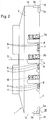
- Each individual indexable insert 3a is received in a recess or pocket 6, which is provided in the end face 4 of the knife carrier base body 2, as can be clearly seen in FIG. 2.
- Each of these depressions or pockets 4 is delimited by a base seat 7, a long side seat 8 and a transverse side seat 9.
- the mutual association of the base seat 7 and the longitudinal side seat 8 of the recesses or pockets 6 can be seen in FIG. 2 of the drawing, while the mutual association of the longitudinal side seats 8 and the transverse side seats 9 is shown in FIG. 1 of this drawing can be.
- the base seat of each recess or pocket 5 has, at least in the feed direction of the milling cutter head 1, an inclination position which determines the clearance angle of the indexable inserts 3a against the plane of rotation 10-10 of the base body 2 of the knife holder.
- the long side seating surfaces 8 and the transverse Seating surfaces 9 have an orientation and arrangement relative to the basic seating surface 7, which is determined by the predetermined basic shape of the indexable inserts 3 used.
- each individual insert 3a in the recess or pocket 6 on the end face 4 of the knife carrier base body 2 can be detachably and interchangeably fixed by a single clamping screw 11 acting centrally on the surface.
- the milling cutter head 1 shown in FIGS. 1 and 2 of the drawing is not only to be used as a face milling head for finishing or fine finishing machining of workpiece surfaces, but also enables use as a so-called roughing / finishing face mill the knife carrier base body 2 is also equipped on its circumferential circumferential surface 12 with indexable inserts 3b.
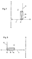
- the indexable inserts 3b on its circumferential circumferential surface 12 are oriented essentially in the direction of the axis of rotation 5-5 of the knife carrier base body, that is to say arranged upright, as it were from FIG. 2 can be seen.
- the indexable inserts 3b on the circumferential circumferential surface 12 of the knife carrier base body 2 also have an arrangement which is uniformly distributed in the circumferential direction.
- Each indexable insert 3b also lies in a recess or pocket 13 which is incorporated into the circumferential circumferential surface 12 of the knife carrier base body 2 and is delimited by a base seat surface 14, a longitudinal side seat surface 15 and a transverse side seat surface 16.
- the base seat 14 on the knife carrier base body 2 is provided at least in the feed direction of the milling cutter head 1 with an inclination position which determines the clearance angle of the indexable insert 3b relative to the circumferential circumferential surface 12 of the knife carrier base body 2.
- a special feature of the milling cutter head 1 according to FIGS. 1 and 2 of the Drawing is that the circumferential area of the knife carrier base body 2 is provided evenly and alternately on the one hand on its end face 4 and on the other hand on its peripheral circumferential surface 12 with the depressions or pockets 6 and 13 for receiving an indexable insert 3a and 3b. That is, in each case in the spacing area between two indexable inserts 3a mounted on the end face of the knife carrier base body 2, an indexable insert 3b is also mounted on the circumferential circumferential surface 12 thereof and vice versa.
- the cutting stations of the milling cutter head 1 are always provided half on the end face 4 of the knife carrier base body 2 and half on the circumferential circumferential surface 12 of the knife carrier base body 2, and are evenly distributed over the circumference .
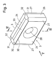
- FIGS. 3 to 6 of the drawing has an essentially rectangular cuboid shape with two mutually parallel but mutually facing side surfaces 21 and 22, with a base surface 23 and a top surface 24 which run parallel to one another and are facing away from one another and two in turn end faces 25 and 26 which are parallel to one another and facing away from one another, as can be seen in FIGS. 4 to 6.
- transition radii 27 are provided there, as can be seen in FIGS. 3 and 6 of the drawing.
- a passage 28 is incorporated into each indexable insert 3, into which a countersink 29 opens from each of the side surfaces 21 and 22.
- Passage 28 and counterbores 29 serve to receive the clamping screws 11 already mentioned above for fastening the indexable inserts 3 to the knife carrier base body 2.
- the indexable inserts 3 shown in FIGS. 3 to 6 of the drawing have such a configuration that each of them can be used in eight different positions of use on a milling cutter head 1 of the type already described with reference to FIGS. 1 and 2 before regrinding of their cutting edges is necessary.
- Each indexable insert 3 with the configuration shown in FIGS. 3 to 6 can be attached as an indexable insert 3a in four different installation positions to the end face 4 of the knife carrier base body 2 and can also be used as an indexable insert 3b in four different installation positions of the circumferential Shell surface 12 of the knife carrier base body 2 can be assigned.
- a milling cutter head 1 according to FIGS. 1 and 2 with indexable inserts 3 according to FIGS. 3 to 6 has a considerably increased utility value.
- indexable inserts 3 have four - long - cutting edges 30, two of which extend along the longitudinal edges of the side surface 21 and the other two along the longitudinal edges of the side surface 22.
- Each of the cutting edges 30 does not have an absolutely rectilinear course, but rather a so-called curved section contour, as can be seen in FIG. 3 of the drawing.
- each indexable insert 30 is also equipped with eight quarter-circular cutting edges 32, each of which runs along a transition radius 27 which leads from one of the side surfaces 21 or 22 to one of the end surfaces 25 and 26.
- Two with long, curved cutting edges 30 and two - short - straight cutting edges 31 and four cutting edges 32 are provided on the base 23 and on the top surface 24 of an indexable insert 3.
- chip recesses 33 are formed in the base surface 23 and in the cover surface 24, which extend along the side surfaces 21 and 22. Similar chip troughs 34 are also formed in the base surface 23 and the cover surface 24, which extend along the end surfaces 25 and 26. In the area of the transition radii 27, a chip recess 33 and a chip recess 34 merge into one another in order to also provide the quarter-circle cutting edges 32 there with a positive wedge angle.
- a cutting edge 32 which runs in a curved arc works as a main cutting edge, while the adjoining short cutting edge 31 forms the associated secondary cutting edge , because the indexable insert 3b is mounted on the knife carrier base body 2 with a standing arrangement, so to speak.
- each insert 3 in the design form shown in FIGS. 3 to 6 can be used on one and the same knife carrier base body without any reworking in eight different installation positions, what has a positive impact on their overall lifespan, of course.
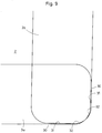
- FIG. 9 of the drawing the cut-out area of the milling cutter head 1 identified by IX in FIG. 2 can be seen on a greatly enlarged scale.
- the indexable inserts 3a mounted on the end face 4 of the knife carrier base body 2 with their minor cutting edge 30 in the axial direction are slightly, for example by a measure of 0.05 mm above the minor cutting edge 31 of the on the peripheral circumferential surface 12 of the knife carrier -Ground the basic body 2 attached indexable inserts 3b.
Landscapes
- Engineering & Computer Science (AREA)
- Mechanical Engineering (AREA)
- Milling Processes (AREA)
- Turning (AREA)
- Auxiliary Devices For Machine Tools (AREA)
Applications Claiming Priority (2)
| Application Number | Priority Date | Filing Date | Title |
|---|---|---|---|
| DE29516668U | 1995-10-21 | ||
| DE29516668U DE29516668U1 (de) | 1995-10-21 | 1995-10-21 | Werkzeug zur spanenden Bearbeitung von Werkst}cken |
Publications (2)
| Publication Number | Publication Date |
|---|---|
| EP0769341A1 true EP0769341A1 (fr) | 1997-04-23 |
| EP0769341B1 EP0769341B1 (fr) | 2002-01-30 |
Family
ID=8014410
Family Applications (1)
| Application Number | Title | Priority Date | Filing Date |
|---|---|---|---|
| EP96115995A Expired - Lifetime EP0769341B1 (fr) | 1995-10-21 | 1996-10-05 | Outil pour l'usinage de pièces par enlèvement de copeaux |
Country Status (4)
| Country | Link |
|---|---|
| EP (1) | EP0769341B1 (fr) |
| BR (1) | BR9606882A (fr) |
| DE (2) | DE29516668U1 (fr) |
| WO (1) | WO1997017157A1 (fr) |
Cited By (9)
| Publication number | Priority date | Publication date | Assignee | Title |
|---|---|---|---|---|
| WO2003101655A1 (fr) * | 2002-06-04 | 2003-12-11 | Iscar Ltd. | Plaquette de coupe tangentielle et fraise |
| EP1380375A1 (fr) * | 2002-07-11 | 2004-01-14 | Wilhelm Fette GmbH | Plaquette de coupe indexable tangentielle |
| WO2005028149A1 (fr) * | 2003-09-24 | 2005-03-31 | Iscar Ltd. | Insert de fraise a coupe tangentielle et fraise |
| US7094007B2 (en) | 2002-12-04 | 2006-08-22 | Iscar Ltd. | Tangential cutting insert and milling cutter |
| BG65121B1 (bg) * | 2002-12-04 | 2007-03-30 | Iscar Ltd | Тангенциална режеща вложка и челна фреза |
| WO2012104832A1 (fr) | 2011-01-31 | 2012-08-09 | Iscar Ltd. | Insert de coupe tangentiel et fraise |
| US8616866B2 (en) | 2011-08-14 | 2013-12-31 | Iscar, Ltd. | Apparatus and method for manufacturing cutting inserts |
| EP2805787A1 (fr) | 2004-09-02 | 2014-11-26 | Ingersoll Cutting Tool Company | Plaquette de coupe tangentielle |
| EP3009217A1 (fr) | 2014-10-13 | 2016-04-20 | Sandvik Intellectual Property AB | Insert de coupe tangentielle et outil de fraisage le comportant |
Families Citing this family (14)
| Publication number | Priority date | Publication date | Assignee | Title |
|---|---|---|---|---|
| DE19704931C1 (de) * | 1997-02-10 | 1998-03-12 | Widia Gmbh | Schneideinsatz und Fräswerkzeug |
| DE19736379A1 (de) | 1997-02-10 | 1999-02-25 | Widia Gmbh | Schneideinsatz und Fräswerkzeug |
| IL129297A (en) | 1998-07-13 | 2002-12-01 | Iscar Ltd | Tangential cutting insert |
| IL148535A (en) | 2002-03-06 | 2009-02-11 | Gil Hecht | Metal cutting tool |
| IL160223A (en) | 2004-02-04 | 2008-11-26 | Carol Smilovici | Double-sided cutting insert and milling cutter |
| RU2279332C2 (ru) * | 2004-08-12 | 2006-07-10 | Дмитрий Валерьевич Попов | Торцово-цилиндрическая фреза |
| JP4231496B2 (ja) | 2005-08-01 | 2009-02-25 | 住友電工ハードメタル株式会社 | スローアウェイチップ |
| RU2482941C2 (ru) * | 2011-06-29 | 2013-05-27 | Государственное образовательное учреждение высшего профессионального образования "Владимирский государственный университет имени Александра Григорьевича и Николая Григорьевича Столетовых" (ВлГУ) | Сборная торцовая фреза |
| KR101380884B1 (ko) | 2012-06-14 | 2014-04-02 | 한국야금 주식회사 | 양면형 절삭 인서트 |
| RU2550680C2 (ru) * | 2013-08-21 | 2015-05-10 | Общество с ограниченной ответственностью "Сборные конструкции инструмента, фрезы Москвитина" | Режущая пластина и дисковая фреза |
| US9205499B2 (en) * | 2013-09-11 | 2015-12-08 | Kennametal Inc. | Cutting insert with finishing and roughing cutting edges |
| US9475138B2 (en) * | 2014-01-22 | 2016-10-25 | Kennametal Inc. | Cutting tool having insert pocket with cantilevered member |
| CN109834327A (zh) * | 2019-01-30 | 2019-06-04 | 北京金万众机械科技有限公司 | 一种能够进行粗加工和精加工的复合面铣刀 |
| EP4197678A1 (fr) | 2021-12-17 | 2023-06-21 | Seco Tools AB | Insert de coupe tangentiel à double face |
Citations (1)
| Publication number | Priority date | Publication date | Assignee | Title |
|---|---|---|---|---|
| EP0287711A2 (fr) * | 1987-04-17 | 1988-10-26 | WALTER Aktiengesellschaft | Outil de fraisage et de perçage |
Family Cites Families (4)
| Publication number | Priority date | Publication date | Assignee | Title |
|---|---|---|---|---|
| US3762005A (en) * | 1970-08-28 | 1973-10-02 | Ingersoll Milling Machine Co | Indexable cutting insert |
| US3716900A (en) * | 1972-02-25 | 1973-02-20 | Ingersoll Milling Machine Co | Indexable cutting insert and holder therefor |
| JPS55144921A (en) * | 1979-04-23 | 1980-11-12 | Azumi Kk | Throw away type ring cutter for roughly cutting groove |
| US4993891A (en) * | 1990-02-20 | 1991-02-19 | General Motors Corporation | Milling cutter with grinding inserts |
-
1995
- 1995-10-21 DE DE29516668U patent/DE29516668U1/de not_active Expired - Lifetime
-
1996
- 1996-10-05 EP EP96115995A patent/EP0769341B1/fr not_active Expired - Lifetime
- 1996-10-05 DE DE59608670T patent/DE59608670D1/de not_active Expired - Lifetime
- 1996-11-05 WO PCT/US1996/017587 patent/WO1997017157A1/fr not_active Ceased
- 1996-11-05 BR BR9606882A patent/BR9606882A/pt not_active IP Right Cessation
Patent Citations (1)
| Publication number | Priority date | Publication date | Assignee | Title |
|---|---|---|---|---|
| EP0287711A2 (fr) * | 1987-04-17 | 1988-10-26 | WALTER Aktiengesellschaft | Outil de fraisage et de perçage |
Cited By (22)
| Publication number | Priority date | Publication date | Assignee | Title |
|---|---|---|---|---|
| RU2304037C2 (ru) * | 2002-06-04 | 2007-08-10 | Искар Лтд. | Тангенциальная режущая пластина и фреза |
| WO2003101655A1 (fr) * | 2002-06-04 | 2003-12-11 | Iscar Ltd. | Plaquette de coupe tangentielle et fraise |
| CN1329154C (zh) * | 2002-06-04 | 2007-08-01 | 伊斯卡有限公司 | 切向切削刀片和铣刀 |
| EP1380375A1 (fr) * | 2002-07-11 | 2004-01-14 | Wilhelm Fette GmbH | Plaquette de coupe indexable tangentielle |
| DE10231339B3 (de) * | 2002-07-11 | 2004-01-22 | Fette Gmbh | Tangential-Wendeschneidplatte |
| US6966729B2 (en) | 2002-07-11 | 2005-11-22 | Fette Gmbh | Tangential reversible cutting blade |
| US7094007B2 (en) | 2002-12-04 | 2006-08-22 | Iscar Ltd. | Tangential cutting insert and milling cutter |
| BG65121B1 (bg) * | 2002-12-04 | 2007-03-30 | Iscar Ltd | Тангенциална режеща вложка и челна фреза |
| KR100892552B1 (ko) * | 2003-09-24 | 2009-04-09 | 이스카 엘티디. | 접선 커팅 인서트 및 밀링 커터 |
| CN100400210C (zh) * | 2003-09-24 | 2008-07-09 | 伊斯卡有限公司 | 切向切削镶块和铣刀 |
| WO2005028149A1 (fr) * | 2003-09-24 | 2005-03-31 | Iscar Ltd. | Insert de fraise a coupe tangentielle et fraise |
| RU2354511C2 (ru) * | 2003-09-24 | 2009-05-10 | Искар Лтд. | Тангенциальная режущая пластина и фреза |
| EP2805787A1 (fr) | 2004-09-02 | 2014-11-26 | Ingersoll Cutting Tool Company | Plaquette de coupe tangentielle |
| WO2012104832A1 (fr) | 2011-01-31 | 2012-08-09 | Iscar Ltd. | Insert de coupe tangentiel et fraise |
| US8702353B2 (en) | 2011-01-31 | 2014-04-22 | Iscar, Ltd. | Tangential cutting insert and milling cutter |
| US8734712B2 (en) | 2011-08-14 | 2014-05-27 | Iscar, Ltd. | Apparatus and method for manufacturing cutting inserts |
| US8616866B2 (en) | 2011-08-14 | 2013-12-31 | Iscar, Ltd. | Apparatus and method for manufacturing cutting inserts |
| EP3009217A1 (fr) | 2014-10-13 | 2016-04-20 | Sandvik Intellectual Property AB | Insert de coupe tangentielle et outil de fraisage le comportant |
| WO2016058803A1 (fr) * | 2014-10-13 | 2016-04-21 | Sandvik Intellectual Property Ab | Plaquette de coupe tangentielle et outil de fraisage comportant une telle plaquette de coupe |
| CN106794525A (zh) * | 2014-10-13 | 2017-05-31 | 山特维克知识产权股份有限公司 | 切向切削刀片和包括该切削刀片的铣刀 |
| US10016822B2 (en) | 2014-10-13 | 2018-07-10 | Sandvik Intellectual Property Ab | Tangential cutting insert and milling tool comprising such a cutting insert |
| CN106794525B (zh) * | 2014-10-13 | 2019-06-14 | 山特维克知识产权股份有限公司 | 切向切削刀片和包括该切削刀片的铣刀 |
Also Published As
| Publication number | Publication date |
|---|---|
| DE59608670D1 (de) | 2002-03-14 |
| EP0769341B1 (fr) | 2002-01-30 |
| BR9606882A (pt) | 1997-10-28 |
| DE29516668U1 (de) | 1995-12-14 |
| WO1997017157A1 (fr) | 1997-05-15 |
Similar Documents
| Publication | Publication Date | Title |
|---|---|---|
| EP0769341B1 (fr) | Outil pour l'usinage de pièces par enlèvement de copeaux | |
| DE69520233T2 (de) | Universelle schneideinsatzaufnahme für tiefschneide- und planfräser | |
| DE69618112T2 (de) | Schneideinsatz für fräser | |
| WO1998034747A1 (fr) | Plaquette de coupe et outil de fraisage | |
| EP1907158B1 (fr) | Element de coupe a inserer, outil et procede d'usinage d'une piece | |
| DE2137635A1 (de) | Werkzeug zur spanabhebenden Bearbeitung, insbesondere Fräsmesserkopf | |
| WO1999067046A1 (fr) | Plaquette de coupe, outil de coupe et procede d'usinage par enlevement de matiere, notamment de surfaces de pieces a symetrie de revolution | |
| EP3347154A1 (fr) | Outil de filetage à la volée | |
| DE19743971B4 (de) | Schneideinsatz, Fräswerkzeug und Verwendung des Fräswerkzeuges | |
| EP1224992A2 (fr) | Outil de coupe et plaquette amovible | |
| EP1140408A1 (fr) | Piece de coupe rapportee et outil muni d'une piece de coupe rapportee | |
| DE3314049C2 (fr) | ||
| AT398049B (de) | Werkzeugträger zum wirbeln bzw. schälen von aussengewinden, schnecken und profilen | |
| DE19517311A1 (de) | Schneidplattenanordnung für Bohrwerkzeug | |
| DE19518483A1 (de) | Werkzeugmaschine für die stirnseitige Bearbeitung von Zahnrädern | |
| DE1552544A1 (de) | Als Wendeschneidplatte ausgebildetes,vorzugsweise aus Hartmetall bestehendes Schneidelement zur Bestueckung von rundlaufenden,mit Spanneinrichtungen ausgeruesteten Werkzeugen,insbesondere fuer die Metallbearbeitung sowie mit diesen Wendeschneidplatten bestueckte Werkzeuge | |
| DE2805670A1 (de) | Rotierendes schneidwerkzeug | |
| DE10333621B4 (de) | Schneideinsatz | |
| DE2713529A1 (de) | Schneidwerkzeug, insbesondere ausdrehmeissel fuer dreh-, bohr- oder aehnliche maschinen | |
| DE3504296C2 (fr) | ||
| DE2808866C2 (de) | Bohrwerkzeug für Bohrungen in Metallvollmaterial | |
| DE2322825C2 (de) | Schneidwerkzeug für Drehmaschinen | |
| DE9320349U1 (de) | Auswechselbare Fräser-Schneideinsätze | |
| AT291520B (de) | Bohr- und Innenprofil-Nutenfräser | |
| DD280485A1 (de) | Schneideinsatz fuer kombinierte fraes- und anfaswerkzeuge |
Legal Events
| Date | Code | Title | Description |
|---|---|---|---|
| PUAI | Public reference made under article 153(3) epc to a published international application that has entered the european phase |
Free format text: ORIGINAL CODE: 0009012 |
|
| 17P | Request for examination filed |
Effective date: 19961028 |
|
| AK | Designated contracting states |
Kind code of ref document: A1 Designated state(s): DE FR GB IT |
|
| GRAG | Despatch of communication of intention to grant |
Free format text: ORIGINAL CODE: EPIDOS AGRA |
|
| 17Q | First examination report despatched |
Effective date: 20010516 |
|
| GRAG | Despatch of communication of intention to grant |
Free format text: ORIGINAL CODE: EPIDOS AGRA |
|
| GRAH | Despatch of communication of intention to grant a patent |
Free format text: ORIGINAL CODE: EPIDOS IGRA |
|
| GRAH | Despatch of communication of intention to grant a patent |
Free format text: ORIGINAL CODE: EPIDOS IGRA |
|
| GRAA | (expected) grant |
Free format text: ORIGINAL CODE: 0009210 |
|
| STAA | Information on the status of an ep patent application or granted ep patent |
Free format text: STATUS: THE PATENT HAS BEEN GRANTED |
|
| REG | Reference to a national code |
Ref country code: GB Ref legal event code: IF02 |
|
| RAP1 | Party data changed (applicant data changed or rights of an application transferred) |
Owner name: INGERSOLL WERKZEUGE GMBH |
|
| AK | Designated contracting states |
Kind code of ref document: B1 Designated state(s): DE FR GB IT |
|
| REF | Corresponds to: |
Ref document number: 59608670 Country of ref document: DE Date of ref document: 20020314 |
|
| GBT | Gb: translation of ep patent filed (gb section 77(6)(a)/1977) |
Effective date: 20020430 |
|
| ET | Fr: translation filed | ||
| PLBQ | Unpublished change to opponent data |
Free format text: ORIGINAL CODE: EPIDOS OPPO |
|
| PLBI | Opposition filed |
Free format text: ORIGINAL CODE: 0009260 |
|
| PLBF | Reply of patent proprietor to notice(s) of opposition |
Free format text: ORIGINAL CODE: EPIDOS OBSO |
|
| 26 | Opposition filed |
Opponent name: SANDVIK AB Effective date: 20021018 |
|
| PLBF | Reply of patent proprietor to notice(s) of opposition |
Free format text: ORIGINAL CODE: EPIDOS OBSO |
|
| PG25 | Lapsed in a contracting state [announced via postgrant information from national office to epo] |
Ref country code: IT Free format text: LAPSE BECAUSE OF NON-PAYMENT OF DUE FEES Effective date: 20091005 |
|
| PGRI | Patent reinstated in contracting state [announced from national office to epo] |
Ref country code: IT Effective date: 20110616 |
|
| REG | Reference to a national code |
Ref country code: FR Ref legal event code: PLFP Year of fee payment: 20 |
|
| PGFP | Annual fee paid to national office [announced via postgrant information from national office to epo] |
Ref country code: GB Payment date: 20150904 Year of fee payment: 20 |
|
| PGFP | Annual fee paid to national office [announced via postgrant information from national office to epo] |
Ref country code: FR Payment date: 20150918 Year of fee payment: 20 |
|
| PGFP | Annual fee paid to national office [announced via postgrant information from national office to epo] |
Ref country code: IT Payment date: 20150810 Year of fee payment: 20 Ref country code: DE Payment date: 20150825 Year of fee payment: 20 |
|
| REG | Reference to a national code |
Ref country code: DE Ref legal event code: R071 Ref document number: 59608670 Country of ref document: DE |
|
| REG | Reference to a national code |
Ref country code: GB Ref legal event code: PE20 Expiry date: 20161004 |
|
| PG25 | Lapsed in a contracting state [announced via postgrant information from national office to epo] |
Ref country code: GB Free format text: LAPSE BECAUSE OF EXPIRATION OF PROTECTION Effective date: 20161004 |
|
| PLAB | Opposition data, opponent's data or that of the opponent's representative modified |
Free format text: ORIGINAL CODE: 0009299OPPO |
|
| R26 | Opposition filed (corrected) |
Opponent name: SANDVIK AB Effective date: 20021018 |
|
| PLAB | Opposition data, opponent's data or that of the opponent's representative modified |
Free format text: ORIGINAL CODE: 0009299OPPO |
|
| R26 | Opposition filed (corrected) |
Opponent name: SANDVIK AB Effective date: 20021018 |