EP0769420A2 - Lautsprecher-Montagebaugruppe für Kraftfahrzeuge - Google Patents
Lautsprecher-Montagebaugruppe für Kraftfahrzeuge Download PDFInfo
- Publication number
- EP0769420A2 EP0769420A2 EP96116452A EP96116452A EP0769420A2 EP 0769420 A2 EP0769420 A2 EP 0769420A2 EP 96116452 A EP96116452 A EP 96116452A EP 96116452 A EP96116452 A EP 96116452A EP 0769420 A2 EP0769420 A2 EP 0769420A2
- Authority
- EP
- European Patent Office
- Prior art keywords
- speaker
- support shaft
- mount structure
- structure according
- decorative panel
- Prior art date
- Legal status (The legal status is an assumption and is not a legal conclusion. Google has not performed a legal analysis and makes no representation as to the accuracy of the status listed.)
- Granted
Links
- XEEYBQQBJWHFJM-UHFFFAOYSA-N Iron Chemical compound [Fe] XEEYBQQBJWHFJM-UHFFFAOYSA-N 0.000 claims abstract description 86
- 229910052742 iron Inorganic materials 0.000 claims abstract description 43
- 241001247986 Calotropis procera Species 0.000 claims description 7
- 230000008878 coupling Effects 0.000 claims description 5
- 238000010168 coupling process Methods 0.000 claims description 5
- 238000005859 coupling reaction Methods 0.000 claims description 5
- 230000002093 peripheral effect Effects 0.000 claims 4
- 239000004033 plastic Substances 0.000 claims 1
- 230000002159 abnormal effect Effects 0.000 abstract description 10
- 239000011347 resin Substances 0.000 description 7
- 229920005989 resin Polymers 0.000 description 7
- 229910052782 aluminium Inorganic materials 0.000 description 6
- XAGFODPZIPBFFR-UHFFFAOYSA-N aluminium Chemical compound [Al] XAGFODPZIPBFFR-UHFFFAOYSA-N 0.000 description 6
- 239000000853 adhesive Substances 0.000 description 4
- 230000001070 adhesive effect Effects 0.000 description 4
- 238000000034 method Methods 0.000 description 4
- 230000008569 process Effects 0.000 description 4
- 238000004519 manufacturing process Methods 0.000 description 3
- 229910052751 metal Inorganic materials 0.000 description 2
- 239000002184 metal Substances 0.000 description 2
- 230000035939 shock Effects 0.000 description 2
- RYGMFSIKBFXOCR-UHFFFAOYSA-N Copper Chemical compound [Cu] RYGMFSIKBFXOCR-UHFFFAOYSA-N 0.000 description 1
- 229920000742 Cotton Polymers 0.000 description 1
- JOYRKODLDBILNP-UHFFFAOYSA-N Ethyl urethane Chemical compound CCOC(N)=O JOYRKODLDBILNP-UHFFFAOYSA-N 0.000 description 1
- ISWSIDIOOBJBQZ-UHFFFAOYSA-N Phenol Chemical compound OC1=CC=CC=C1 ISWSIDIOOBJBQZ-UHFFFAOYSA-N 0.000 description 1
- HCHKCACWOHOZIP-UHFFFAOYSA-N Zinc Chemical compound [Zn] HCHKCACWOHOZIP-UHFFFAOYSA-N 0.000 description 1
- 229920000122 acrylonitrile butadiene styrene Polymers 0.000 description 1
- 230000008859 change Effects 0.000 description 1
- ZCDOYSPFYFSLEW-UHFFFAOYSA-N chromate(2-) Chemical compound [O-][Cr]([O-])(=O)=O ZCDOYSPFYFSLEW-UHFFFAOYSA-N 0.000 description 1
- 239000011889 copper foil Substances 0.000 description 1
- 238000005034 decoration Methods 0.000 description 1
- 238000004512 die casting Methods 0.000 description 1
- 230000000694 effects Effects 0.000 description 1
- 239000004744 fabric Substances 0.000 description 1
- 239000006260 foam Substances 0.000 description 1
- 239000003365 glass fiber Substances 0.000 description 1
- 238000002347 injection Methods 0.000 description 1
- 239000007924 injection Substances 0.000 description 1
- 239000000463 material Substances 0.000 description 1
- QEFYFXOXNSNQGX-UHFFFAOYSA-N neodymium atom Chemical group [Nd] QEFYFXOXNSNQGX-UHFFFAOYSA-N 0.000 description 1
- 229910001172 neodymium magnet Inorganic materials 0.000 description 1
- 229920001721 polyimide Polymers 0.000 description 1
- 239000009719 polyimide resin Substances 0.000 description 1
- 238000004804 winding Methods 0.000 description 1
- 229910052725 zinc Inorganic materials 0.000 description 1
- 239000011701 zinc Substances 0.000 description 1
Images




Classifications
-
- B—PERFORMING OPERATIONS; TRANSPORTING
- B60—VEHICLES IN GENERAL
- B60R—VEHICLES, VEHICLE FITTINGS, OR VEHICLE PARTS, NOT OTHERWISE PROVIDED FOR
- B60R11/00—Arrangements for holding or mounting articles, not otherwise provided for
- B60R11/02—Arrangements for holding or mounting articles, not otherwise provided for for radio sets, television sets, telephones, or the like; Arrangement of controls thereof
- B60R11/0217—Arrangements for holding or mounting articles, not otherwise provided for for radio sets, television sets, telephones, or the like; Arrangement of controls thereof for loud-speakers
-
- B—PERFORMING OPERATIONS; TRANSPORTING
- B60—VEHICLES IN GENERAL
- B60R—VEHICLES, VEHICLE FITTINGS, OR VEHICLE PARTS, NOT OTHERWISE PROVIDED FOR
- B60R11/00—Arrangements for holding or mounting articles, not otherwise provided for
- B60R2011/0001—Arrangements for holding or mounting articles, not otherwise provided for characterised by position
- B60R2011/0003—Arrangements for holding or mounting articles, not otherwise provided for characterised by position inside the vehicle
- B60R2011/0019—Side or rear panels
- B60R2011/0021—Doors
-
- B—PERFORMING OPERATIONS; TRANSPORTING
- B60—VEHICLES IN GENERAL
- B60R—VEHICLES, VEHICLE FITTINGS, OR VEHICLE PARTS, NOT OTHERWISE PROVIDED FOR
- B60R11/00—Arrangements for holding or mounting articles, not otherwise provided for
- B60R2011/0042—Arrangements for holding or mounting articles, not otherwise provided for characterised by mounting means
- B60R2011/0043—Arrangements for holding or mounting articles, not otherwise provided for characterised by mounting means for integrated articles, i.e. not substantially protruding from the surrounding parts
- B60R2011/0045—Arrangements for holding or mounting articles, not otherwise provided for characterised by mounting means for integrated articles, i.e. not substantially protruding from the surrounding parts with visible part, e.g. flush mounted
- B60R2011/0047—Arrangements for holding or mounting articles, not otherwise provided for characterised by mounting means for integrated articles, i.e. not substantially protruding from the surrounding parts with visible part, e.g. flush mounted using hidden fastening means
Definitions
- the present invention relates to a speaker mount structure of a vehicle, and more particularly to a speaker mount structure in which a light and thin speaker, such as a speaker with a repulsion magnetic circuit, is mounted on an interior decorative panel, a door panel, or the like of a vehicle, and the panel with the speaker mounted thereon is mounted to a vehicle body, a door, or the like.
- a light and thin speaker such as a speaker with a repulsion magnetic circuit
- a conventional vehicle speaker mount structure such as the mount structure of a speaker on a door panel or inner decorative panel
- Wiring to switches and the like for a power window mounted on the door panel or the like and wiring to a speaker can be collectively processed. Therefore, the speaker and switches and the like of the power window can be assembled with the door panel or the like and can be formed into one module.
- This module of the panel is mounted on a vehicle so that the number of mount processes can be reduced.
- a speaker is not mounted on an inner decorative panel, a door panel, or the like for the following reasons.
- a general vehicle door panel will be described by way of example.
- Many door panels are about 3 to 4 mm thick and are made of resin such as FRP or pulp compressed plate called a hard beard.
- Many conventional speakers such as 5 inch or 6.5 inch speakers have an average weight of about 550 g to 750 g.
- the strength of a door panel is insufficient for mounting such a heavy speaker. If such a vehicle speaker is mounted on the door panel by using screws or the like generally used for mounting speakers, large shocks upon door open/close or during running are applied to the speaker to dismount it. Therefore, screws may be loosened or removed, and the mount portion may be broken to drop the speaker down.
- baffle plate with a general audio speaker mounted thereon is required to have a thickness sufficient for not generating abnormal sounds such as kinky sounds even if a large signal is input.
- a sufficiently thick baffle plate can be used for audio speakers in home use, a door panel or inner decorative panel used for a baffle of a vehicle audio speaker has an insufficient strength because the panel is thin. Therefore, abnormal sounds such as kinky sounds are likely to be generated near at the speaker mount area when a large signal is input, as well known in the art.
- a present speaker mount structure mounts a speaker directly or via a bracket made of resin injection mold or iron press mold, on a vehicle frame made of iron such as a door.
- an elastic ring gasket G made of urethane foam or the like is mounted on a frame flange 1f1.
- This mount structure is used for the above reasons regardless if that the structure is not proper for the sound quality and characteristics of a speaker 1, as well known in the art.
- a door panel or inner decorative panel 3 is useful for decoration of the vehicle room, it has hardly a function of supporting the weight of the speaker 1.
- Recent speakers are becoming light and thin.
- the present inventors have proposed a light and thin speaker.
- This speaker of 6.5 inch diameter is 150 g to 130 g reducing the weight of about 750 g of a conventional speaker by 80 % or more, and has a mounting depth of about 25 mm thinning the thickness of about 50 mm of a conventional speaker by about 50 %. It can be easily thought that such a thin and light speaker 1 mounted on a door panel or inner decorative panel 3 can alleviate conventional inconveniences.
- a thin iron press frame 1f, a thin aluminum press frame 1f, or the like has an insufficient strength.
- the door panel or interior decorative panel 3 with the speaker 1 is mounted on the frame 1 by using fixing screws b with an air driver or the like, not only deflected force is applied to the frame flange 1f1 but also pressure applied to the screw head may deform the flange near at a fixing hole 1f3. This deformation may hinder a mount work of a grille 2 of the speaker 1.
- each screw b is slowly threaded to average the force applied to the flange 1f1 and avoid deflected force.
- a projection-shaped support shaft is provided which protrudes near at the speaker flange from the back of the panel with the speaker.
- the support shaft couples directly, or via a cushioning member made of rubber or the like, to a partial area of a vehicle iron plate or iron door plate.
- the projection-shaped support shaft is provided at the position where the speaker is mounted on the panel, for example, at the position near the speaker flange.
- the support shaft couples directly, or via the cushioning member made of rubber or the like, to a partial area of the vehicle iron plate or iron door plate.
- the support shaft is mounted between the interior decorative panel or door panel and the vehicle iron plate or iron door plate. Accordingly, the speaker mount area of the panel, i.e., the baffle, functions as if it is thickened and the mechanical strength is increased greatly.
- the heads of frame fixing screws do not directly contact the frame as in the conventional case. Specifically, since the screws are threaded via the grille and panel, local pressure to be caused by the screw head is dispersed to the grille and panel. Further, since the pressure to the frame flange is averaged, deformation of the frame can be avoided.
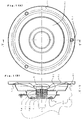
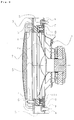
- Fig. 1A is a front view of a speaker according to an embodiment of the present invention and Fig. 1B is a cross sectional view taken along line A-A of Fig. 1A.
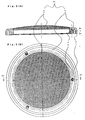
- Fig. 2A is a cross sectional view of a grille of the embodiment and Fig. 2B is a plan view showing the back of the grille,
- Fig. 3 is a cross sectional view showing the positional relationship between components of the speaker of the embodiment before it is mounted.
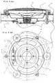
- Fig. 4A is a cross sectional view showing the mount state of the speaker of the embodiment and Fig. 4B is a plan view of the mount state as viewed from the back of the speaker.
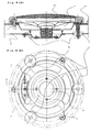
- Fig. 5A is a cross sectional view showing the mount state of a speaker according to another embodiment of the invention and Fig. 5B is a plan view of the mount state as viewed from the back of the speaker.
- Fig. 6A is a cross sectional view showing the mount state of a speaker according to another embodiment of the invention and Fig. 6B is a plan view of the mount state as viewed from the back of the speaker.
- Fig. 7A is a cross sectional view showing the mount state of a speaker according to another embodiment of the invention and Fig. 7B is a plan view of the mount state as viewed from the back of the speaker.
- Fig. 8 is a cross sectional view showing the mount state of a speaker according to another embodiment of the invention.
- Fig. 9 is a cross sectional view showing the mount state of a conventional speaker.
- a speaker 1 used with the embodiments will be described with reference to Fig. 1.
- a speaker frame 1f has a maximum outer diameter of 159 mm and a height of 40 mm and is made of a press molded aluminum plate of 1 mm thick. This speaker frame 1f is generally called a 6.5 inch diameter frame.
- the outer periphery at the maximum outer diameter portion is provided with a protrusion of 7.2 mm high, and a flange 1f1 of about 16 mm wide is formed at the inner side of the flange 1f1.
- the flange 1f1 is formed with three mount holes 1f3 of 5.5 mm diameter for mounting the speaker 1 on a baffle or the like.
- the three mount holes 1f3 are radially positioned at a pitch of 120 degrees and remotely from the center of the frame 1f by 142 mm.
- the inner diameter of the flange 1f1 is 122 mm.
- a fall portion of 4 mm deep is formed contiguously with the inner diameter portion of the flange 1f1.
- a flat ring portion of about 6.3 mm wide generally called a damper seat is formed at the position lower by 25 mm from the fall portion.
- a slanted fall portion of 9 mm deep is formed contiguously with the inner diameter portion of the damper seat.
- the lowest end of the slanted fall portion is contiguous with a frame bottom 1f2 of about 50 mm diameter.
- a frame bottom hole of 33 mm diameter is formed in the frame bottom 1f2 at the central area thereof, i.e., at the central area of the frame 1f.
- Four holes of 4.5 mm diameter for mounting a magnetic holder 1h are formed in the frame bottom 1f2 near the frame bottom hole, radially at a pitch of 90 degrees and remotely from the center of the frame 1f by 45 mm.
- the magnet holder 1h is made of aluminum and has generally an inverted T-character shape in cross section as shown in Fig. 1 or 4.
- the bottom of the magnet holder 1h is a holder flange 1h1 generally a disk shape having an outer diameter of 50 mm and a thickness of about 3 mm.
- a magnet guide pole 1h2 is formed which has a diameter of 5.95 mm and a height of 17 mm.
- Four tapped screw holes of M3 for mounting the magnet holder 1h on the frame bottom 1f2 are formed in the holder flange 1h1, radially at a pitch of 90 degrees and remotely from the center of the holder flange 1h1 by 45 mm.
- a step of 1 mm high as a frame guide is formed on the back of the holder flange 1h1, at the position of 32.6 mm diameter from the center of the holder flange 1h1.
- rubber based adhesive is coated in a ring shape by about 0.3 g on the predetermined area near at the frame guide outer circumference of the holder flange 1h1 of the magnet holder 1h. While the frame guide is inserted into the frame bottom hole, the screw holes of the holder flanges 1h1 and the mount holes of the magnet holder 1h are aligned in position and the frame and magnet holder are pressed securely, and further as shown in Fig. 1B, the magnet holder 1h is fixed to the frame bottom 1f2 by threading flat head screws b from the frame bottom side. In this embodiment, although the screws b are used for mounting, other means may be used, or the frame and magnet holder may be formed integrally.
- magnets 1Ma and 1Mb and a center plate 1p constituting the repulsion magnetic circuit are fitted around the magnet guide 1h2 at the center of the frame bottom 1f2.
- the magnets 1Ma and 1Mb are neodymium ring magnets having an outer diameter of 25 mm, an inner diameter of 6 mm, and a thickness of 8 mm, and are magnetized in the thickness direction.
- the magnets 1Ma and 1Mb fitted about the magnet guide 1h2 of the magnet holder 1h face each other over the center plate 1p, with the N poles thereof being facing each other, i.e., with the center plate 1p being sandwiched between the N pole sides of the magnets 1Ma and 1Mb.
- the center plate 1p is made of iron and has a ring shape having an outer diameter of 25.43 mm, an inner diameter of 6 mm, and a thickness of 3 mm.
- the center plate 1p is plated with zinc subjected to a so-called chromate process.
- repulsion magnetic circuit is fixed by screws b as shown in Fig. 1B, other means such as adhesive may also be used.
- a cone type diaphragm 1c of the vibration system components is made of pulp and has a diameter of 135 mm inclusive its edge portion and a depth of about 13 mm.
- the diaphragm 1c has a hole of about 26 mm diameter generally called a neck at its central area for coupling to a voice coil 1v.
- the voice coil 1v has a bobbin of 0.1 mm thick made of FRP which is polyimide resin reinforced with glass fibers and generally called TIL.
- the voice coil 1v has a winding width of about 4.5 mm and a d.c. resistance of 3.4 ⁇ .
- the voice coil 1v is mounted such that a constant clearance of about 0.26 mm is formed between the outer circumference of the center plate 1p and the inner circumference of the voice coil 1v.
- a copper foil is adhered to the outer circumference of the voice coil bobbin at its predetermined area.
- a damper 1d is made of cotton cloth impregnated with phenol which is thermally molded and punched out.
- Two wires made of flat knitted tinsel wires are being sewn on the damper along corrugations. These vibration system components and magnetic circuit components are mounted on and assembled with the frame 1f.
- the speaker 1 of the embodiment described above has a weight of about 145 g and a mounting depth of 33. 6 mm.
- a grille 2 for the speaker 1 such as shown in Fig. 2 has a ring 21 made of black ABS resin and a punched metal 2p made of iron of 0.5 mm thick painted in black.
- the ring 21 has an outer diameter of 167 mm, an inner diameter of 130.4 mm, and a thickness of about 17 mm.
- Black rubber based adhesive is coated on the inner circumference of the resin ring 21 by about 1.3 g, a fall bent portion formed at the outer circumference of the punched metal 2p is inserted along the inner circumference of the resin ring 21 to thereby adhere them together.
- a ring groove 211 is formed in the ring 21 near at the outer circumference on the bottom side, i.e., on the side to be contacted with the flange 1f1 of the speaker frame 1f.
- the protrusion formed at the outer circumference of the flange 1f1 is inserted into this groove 211.
- This groove 211 has an inner diameter of 151.5 mm, an outer diameter of 159 mm, and a depth of about 10.3 mm.
- Three tapped screw holes 212 of M5 for the mount on the speaker 1 are radially formed on the bottom side of the ring 21 at a pitch of 120 degrees and remotely from the center by 142 mm.
- rubber based adhesive is coated on the frame flange 1f1 of the speaker 1 at its predetermined area by about 1.4 g to adhere the grille 2 and the speaker 1 together by aligning in position the screw holes of the grille 2 and the mount holes 1f3 of the frame 1f.
- the speaker 1 with the grille is mounted on a door panel 3.
- the grille 2 may be mounted on the speaker frame 1f at a different time, depending upon the manufacture process, a production state, or the like. For example, the grille 2 may be mounted at the time when the speaker 1 is mounted on the door panel 3.
- the door panel 3 is formed with a hole 31 at a desired area thereof and three speaker fixing holes 32 having a diameter of 6 mm.
- the hole 31 is generally called an opening and has a diameter of 128 mm.
- the holes 32 correspond to the mount holes 1f3 of the speaker 1 and are radially formed at a pitch of 120 degrees and remotely from the center of the hole 31 by 142 mm.
- the holes 32 are aligned in position with the mount holes 1f3 formed in the frame flange 1f1 of the speaker 1 so that the screw holes 212 of the resin ring are also aligned in position.
- the speaker 1 is fixedly mounted on the door panel 3 by using fixing screws 4b from the back of the panel 3.
- the fixing screws 4b each have a specific shape as shown in Fig. 3.
- the fixing screw 4b will be described with reference to Fig. 3.
- the fixing screw 4b is basically an iron rod having a diameter of 7.3 mm and a length of about 40.3 mm.
- the fixing screw 4b has a threaded portion 4b1 of M5 (an effective threaded portion is 10 mm long) at the lower end thereof, a flange portion 4b2 having a diameter of 12 mm and a thickness of 2 mm at the upper end of the threaded portion 4b1, a circular cylinder portion upright from the flange portion 4b2 having a diameter of 7.3 mm and a length of about 28.3 mm, and a spherical portion 4b4 at the top end having a radius of 2 mm.
- the upper end portion below the spherical portion has a circular cone of 90 degrees in section as shown in Fig. 3.
- a step portion 4b3 having a depth of 1 mm and a width of 6 mm is formed starting from the position lower (left side in Fig. 3) by 3 mm than the lower end of the circular cone.
- the flange portion 4bs is partially cut to form a flat portion having a width of 10 mm which is generally called a spanner guide.
- the frame 1f of the speaker 1 is squeezed by the grille 2 and the door panel 3, with three support shafts 4 having a length of about 30 mm and a diameter of 6 mm being provided on the back of the door panel 3.
- the support shafts 4 may abut against an iron door plate F or the bottom 1f2 of the speaker 1 may contact with or abut against the iron door plate F, depending upon the type of vehicles. In such a case, it is impossible to mount the door panel 3 on the door.
- an opening F1 such as shown in Fig. 4 is formed in the iron door plate F at the area inside of the rubber bushes retracting from the mount areas of the rubber bushes.
- This opening F1 prevents the bottom 1f2 of the speaker 1 from contacting the iron door plate F, increases the apparent cavity capacity, and alleviates a back pressure applied from the diaphragm when a signal is input to thereby suppress the generation of kinky sounds or the like as much as possible.
- each fixing screw 4b i.e., support shaft 4
- the step portion 4b3 of each fixing screw 4b i.e., the support shaft 4 is borne by the cushioning member 5 of the rubber bush, and the support shaft 4 is coupled to a partial area of the iron door plate F via the cushioning member 5.
- the support shaft 4 is coupled to a partial area of a vehicle iron plate F.
- the speaker without support shafts 4 on the back side of the door panel showed no practical problem when a small signal is input or music with less peak signals is played.
- the fixing screw 4b functions as the support shaft 4.
- the support shaft 4 may be integrally formed with a resin grille 2, a resin interior decorative panel 3, or a door panel 3, as shown in Figs. 5 and 6. If the support shaft 4 is difficult or impossible to be integrally formed, it may be mounted as a discrete component. For example, in the case of the speaker frame made of press molded aluminum plate, the support shaft 4 is mounted as a discrete component, and in the case of a speaker frame made of die casting, the support shaft 4 is integrally formed with the speaker frame.
- the cushioning member 5 of a rubber bush or the like is provided on the side of the iron door plate F or vehicle iron plate F at the junction point between the support shaft 4 and iron door plate F or vehicle iron plate F.
- the cushioning member 5 made of rubber or the like may be provided on the side of the support shaft 4 such as shown in Fig. 4, with similar advantageous effects being expected.
- the mount structure of this embodiment is very effective not only for an aluminum press frame but also for general light weight speakers.
- a speaker having a weight of about 200 g to 350 g with a compact magnetic circuit using neodymium magnets and an iron frame whose weight is reduced by 50 % to 60 % can be mounted directly on the panel as shown in Fig. 8 without any deformation of the frame. It was also confirmed that kinky sounds, resonance sounds, and the like were hardly generated and the speaker was sufficiently resistant to shocks upon door open/close or during running. In this embodiment, the speaker is mounted on the door panel.
- the support shaft 4 coupling the door panel or interior decorative panel 3 and the iron door plate or vehicle iron plate F efficiently reinforces the strength of the panel 3. Therefore, even if the speaker 1 is mounted on the door panel or interior decorative panel 3, it is possible to obtain the strength of the panel 3 sufficient for supporting the weight of the speaker 1 and to prevent resonance of the thin panel 3 and kinky sounds or the like.
- the cushioning member 5 of rubber or the like is provided on the iron door plate or vehicle iron plate so that errors of the positions and sizes of the support shafts 4 and the holes formed in the iron door plate or vehicle iron plate can be absorbed. It is therefore very easy to perform position alignment between the door panel or interior decorative panel 3 and the door or vehicle iron plate, reducing the number of manufacture processes. Deformation of the cushioning member 5 leads to a change in rigidity of the panel and shifts the resonance frequency of the panel, further reducing kinky sounds.
- the frame 1f of the speaker 1 is squeezed between the grille 2 and the door panel or interior decorative panel 3 so that local pressure applied to the flange 1f1 of the frame 1f is dispersed and deformation of the frame 1f is prevented. Therefore, even a speaker 1 with a frame 1f easy to be deformed, such as an aluminum press frame or thin and light iron press frame, can be mounted without any deformation.
Landscapes
- Engineering & Computer Science (AREA)
- Mechanical Engineering (AREA)
- Fittings On The Vehicle Exterior For Carrying Loads, And Devices For Holding Or Mounting Articles (AREA)
- Details Of Audible-Bandwidth Transducers (AREA)
Applications Claiming Priority (3)
| Application Number | Priority Date | Filing Date | Title |
|---|---|---|---|
| JP269637/95 | 1995-10-18 | ||
| JP26963795A JP3413741B2 (ja) | 1995-10-18 | 1995-10-18 | 車載用スピーカの装着構造 |
| JP26963795 | 1995-10-18 |
Publications (3)
| Publication Number | Publication Date |
|---|---|
| EP0769420A2 true EP0769420A2 (de) | 1997-04-23 |
| EP0769420A3 EP0769420A3 (de) | 1999-01-07 |
| EP0769420B1 EP0769420B1 (de) | 2002-08-07 |
Family
ID=17475129
Family Applications (1)
| Application Number | Title | Priority Date | Filing Date |
|---|---|---|---|
| EP96116452A Expired - Lifetime EP0769420B1 (de) | 1995-10-18 | 1996-10-14 | Lautsprecher-Montagebaugruppe für Kraftfahrzeuge |
Country Status (5)
| Country | Link |
|---|---|
| US (1) | US5734131A (de) |
| EP (1) | EP0769420B1 (de) |
| JP (1) | JP3413741B2 (de) |
| CN (1) | CN1069271C (de) |
| DE (2) | DE69622812T2 (de) |
Cited By (6)
| Publication number | Priority date | Publication date | Assignee | Title |
|---|---|---|---|---|
| DE19740400A1 (de) * | 1997-09-09 | 1999-03-18 | Brose Fahrzeugteile | Lautsprecheranordnung in einer Kraftfahrzeugtür |
| FR2773840A1 (fr) * | 1998-01-16 | 1999-07-23 | Peugeot | Porte de vehicule comportant un mecanisme leve-vitre et un haut-parleur associe |
| WO2000069687A1 (en) * | 1999-05-18 | 2000-11-23 | Magna Interior Systems, Inc. | Audio speaker mounting assembly for a vehicle panel |
| EP1332921A1 (de) * | 2002-02-05 | 2003-08-06 | Dr.Ing. h.c.F. Porsche Aktiengesellschaft | Befestigungsanordnung eines Lautsprechers an einem Verkleidungsteil eines Fahrzeuges |
| EP1493627A1 (de) * | 2003-06-30 | 2005-01-05 | Pioneer Corporation | An der Fahrzeugtür befestigter Lautsprecher und Fahrzeugtür |
| US6981566B2 (en) | 2002-01-26 | 2006-01-03 | Dr. Ing. H.C.F. Porsche Ag | Drive assembly for a motor vehicle |
Families Citing this family (28)
| Publication number | Priority date | Publication date | Assignee | Title |
|---|---|---|---|---|
| GB2333661B (en) * | 1998-01-26 | 2001-12-05 | Martin Audio Ltd | A mounting arrangement for a loudspeaker or luminaire |
| US6354397B1 (en) * | 2000-06-06 | 2002-03-12 | Multi Service Corporation | Attachment fixture for the front panel and grill of a speaker assembly |
| JP4128999B2 (ja) * | 2002-04-25 | 2008-07-30 | ピーエスエス・ベルギー・エヌブイ | 駆動ユニット、ラウドスピーカ・アセンブリおよびスピーカユニット |
| JP4603829B2 (ja) * | 2003-07-31 | 2010-12-22 | テーダブリュ電気株式会社 | スピーカの取付構造及びスピーカ |
| US7025170B2 (en) * | 2003-11-03 | 2006-04-11 | Steff Lin | Speaker |
| JP2005311500A (ja) * | 2004-04-19 | 2005-11-04 | Toyota Boshoku Corp | 車両用音響装置 |
| JP4901641B2 (ja) * | 2007-08-20 | 2012-03-21 | 日泉化学株式会社 | 異音防止構造 |
| US20090100654A1 (en) * | 2007-10-19 | 2009-04-23 | Nissan Technical Center North America, Inc. | Apparatus and method for attaching covering material to interior components of a vehcile |
| DE102008011084A1 (de) | 2008-02-26 | 2009-08-27 | Daimler Ag | Vorrichtung zur Befestigung eines Lautsprechers |
| EP2119598B1 (de) * | 2008-05-09 | 2010-09-22 | Harman Becker Automotive Systems GmbH | Lautsprecheranordnung und Verfahren zur Befestigung eines Lautsprechers |
| CN101879894A (zh) * | 2010-06-18 | 2010-11-10 | 重庆长安汽车股份有限公司 | 一种汽车用制动防抱死执行机构总成支架 |
| US8428290B2 (en) * | 2011-06-16 | 2013-04-23 | Mipro Electronics Co., Ltd. | Input-panel-equipped portable speaker device |
| JP5946320B2 (ja) * | 2012-05-16 | 2016-07-06 | アルパイン株式会社 | スピーカ用クッション装置およびこれを使用した車載用音響装置 |
| USD752199S1 (en) * | 2014-09-22 | 2016-03-22 | Homewerks Worldwide, LLC | Bath fan with speaker |
| TWI580277B (zh) * | 2015-04-22 | 2017-04-21 | 劉遠振 | 薄型揚聲器 |
| US10260539B2 (en) | 2015-08-13 | 2019-04-16 | Toyota Motor Engineering & Manufacturing North America, Inc. | Connections with selectively variable dampening characteristics |
| JP6478885B2 (ja) * | 2015-09-17 | 2019-03-06 | アルパイン株式会社 | 車載用スピーカ |
| KR101736994B1 (ko) * | 2015-11-26 | 2017-05-17 | 현대자동차주식회사 | 차량에 탑재된 스피커의 그릴 제어 방법 및 장치 |
| USD808001S1 (en) | 2016-03-14 | 2018-01-16 | Homewerks Worldwide, LLC | Square fan grille |
| JP7025705B2 (ja) * | 2017-07-31 | 2022-02-25 | トヨタ紡織株式会社 | 乗物用内装材の製造方法 |
| CN111169393A (zh) * | 2018-11-13 | 2020-05-19 | 上海博泰悦臻网络技术服务有限公司 | 汽车音响及汽车 |
| USD933194S1 (en) | 2019-06-24 | 2021-10-12 | Homewerks Worldwide, LLC | Fan grille |
| USD932611S1 (en) | 2019-06-24 | 2021-10-05 | Homewerks Worldwide, LLC | Fan grille |
| USD933195S1 (en) | 2019-11-26 | 2021-10-12 | Homewerks Worldwide, LLC | Fan grille |
| USD948025S1 (en) | 2019-11-26 | 2022-04-05 | Homewerks Worldwide, LLC | Fan grille |
| USD933809S1 (en) | 2019-11-26 | 2021-10-19 | Homewerks Worldwide, LLC | Fan grille |
| USD932612S1 (en) | 2019-11-26 | 2021-10-05 | Homewerks Worldwide, LLC | Fan grille |
| DE102020204169A1 (de) * | 2020-02-19 | 2021-08-19 | Brose Fahrzeugteile Se & Co. Kommanditgesellschaft, Bamberg | Türbaugruppe mit einem Türmodulträger und einem Lautsprecher |
Family Cites Families (11)
| Publication number | Priority date | Publication date | Assignee | Title |
|---|---|---|---|---|
| US3267993A (en) * | 1964-01-08 | 1966-08-23 | Fennell Corp | Heat transfer system for a liquid bath |
| US4056165A (en) * | 1973-12-29 | 1977-11-01 | Honda Giken Kogyo Kabushiki Kaisha | Sound reproducing apparatus in the inside of a car |
| DE2637487A1 (de) * | 1976-08-20 | 1978-02-23 | Blaupunkt Werke Gmbh | Lautsprechergehaeuse fuer fahrzeuge |
| JPS6019392A (ja) * | 1983-07-13 | 1985-01-31 | Matsushita Electric Ind Co Ltd | 薄形スピ−カ |
| JPS60103987U (ja) * | 1983-12-20 | 1985-07-16 | パイオニア株式会社 | 車載用スピ−カ−等の取付機構 |
| JPS63158082U (de) * | 1987-04-03 | 1988-10-17 | ||
| JPH02138992U (de) * | 1989-04-22 | 1990-11-20 | ||
| CN2173484Y (zh) * | 1993-07-30 | 1994-08-03 | 艾英杰 | 建筑装修用音箱 |
| US5416283A (en) * | 1994-02-17 | 1995-05-16 | Adac Plastics, Inc. | Drop-in speaker mount |
| JP2879879B2 (ja) * | 1994-03-15 | 1999-04-05 | 河西工業株式会社 | スピーカグリルの取付構造 |
| JP3619293B2 (ja) * | 1995-08-07 | 2005-02-09 | 太平洋セメント株式会社 | 密封式超精密微動装置 |
-
1995
- 1995-10-18 JP JP26963795A patent/JP3413741B2/ja not_active Expired - Fee Related
-
1996
- 1996-10-09 US US08/731,053 patent/US5734131A/en not_active Expired - Lifetime
- 1996-10-10 CN CN96120035A patent/CN1069271C/zh not_active Expired - Fee Related
- 1996-10-14 DE DE69622812T patent/DE69622812T2/de not_active Expired - Fee Related
- 1996-10-14 EP EP96116452A patent/EP0769420B1/de not_active Expired - Lifetime
- 1996-10-14 DE DE0769420T patent/DE769420T1/de active Pending
Cited By (9)
| Publication number | Priority date | Publication date | Assignee | Title |
|---|---|---|---|---|
| DE19740400A1 (de) * | 1997-09-09 | 1999-03-18 | Brose Fahrzeugteile | Lautsprecheranordnung in einer Kraftfahrzeugtür |
| DE19740400B4 (de) * | 1997-09-09 | 2004-03-11 | Brose Fahrzeugteile Gmbh & Co. Kg, Coburg | Lautsprecheranordnung in einer Kraftfahrzeugtür |
| FR2773840A1 (fr) * | 1998-01-16 | 1999-07-23 | Peugeot | Porte de vehicule comportant un mecanisme leve-vitre et un haut-parleur associe |
| WO2000069687A1 (en) * | 1999-05-18 | 2000-11-23 | Magna Interior Systems, Inc. | Audio speaker mounting assembly for a vehicle panel |
| US6456722B1 (en) | 1999-05-18 | 2002-09-24 | Magna Interior Systems, Inc. | Speaker mounting assembly for a vehicle panel |
| US6981566B2 (en) | 2002-01-26 | 2006-01-03 | Dr. Ing. H.C.F. Porsche Ag | Drive assembly for a motor vehicle |
| EP1332921A1 (de) * | 2002-02-05 | 2003-08-06 | Dr.Ing. h.c.F. Porsche Aktiengesellschaft | Befestigungsanordnung eines Lautsprechers an einem Verkleidungsteil eines Fahrzeuges |
| US6918462B2 (en) | 2002-02-05 | 2005-07-19 | Dr. Ing. H.C.F. Porsche Ag | Fastening arrangement for an upholstery part covering a vehicle loudspeaker |
| EP1493627A1 (de) * | 2003-06-30 | 2005-01-05 | Pioneer Corporation | An der Fahrzeugtür befestigter Lautsprecher und Fahrzeugtür |
Also Published As
| Publication number | Publication date |
|---|---|
| DE69622812T2 (de) | 2003-02-27 |
| CN1153117A (zh) | 1997-07-02 |
| DE769420T1 (de) | 1997-09-04 |
| JP3413741B2 (ja) | 2003-06-09 |
| EP0769420B1 (de) | 2002-08-07 |
| DE69622812D1 (de) | 2002-09-12 |
| JPH09109789A (ja) | 1997-04-28 |
| EP0769420A3 (de) | 1999-01-07 |
| US5734131A (en) | 1998-03-31 |
| CN1069271C (zh) | 2001-08-08 |
Similar Documents
| Publication | Publication Date | Title |
|---|---|---|
| EP0769420B1 (de) | Lautsprecher-Montagebaugruppe für Kraftfahrzeuge | |
| JPH11355883A (ja) | スピーカ装置 | |
| US6278787B1 (en) | Loudspeakers | |
| EP1091616B1 (de) | Lautsprechersmembran | |
| JP3924918B2 (ja) | 楕円型スピーカ | |
| JP3260062B2 (ja) | スピーカ | |
| US4926487A (en) | Speaker system | |
| CN117156359B (zh) | 一种双音盆的扬声器及其装配方法、汽车音响系统 | |
| US20100208934A1 (en) | Speaker device | |
| US12335705B2 (en) | Speaker | |
| US20050276436A1 (en) | Speaker device | |
| JP3161679B2 (ja) | スピーカ | |
| US7324658B2 (en) | Speaker | |
| US20100177925A1 (en) | Speaker Device | |
| CN117956381A (zh) | 一种扬声器的组装方法及扬声器 | |
| US20050271244A1 (en) | Resin frame, resin grille and speaker device | |
| JPH053596A (ja) | スピーカ | |
| CN221329117U (zh) | 一种扬声器 | |
| CN113993040A (zh) | 喇叭中心定位限幅器及喇叭 | |
| CN217825360U (zh) | 一种扬声器 | |
| CN223600021U (zh) | 一种侧出音的喇叭结构 | |
| CN223744896U (zh) | 一种振动抑制扬声器的振动缓冲件 | |
| JP2607332Y2 (ja) | スピーカ用フレーム | |
| JP2600037Y2 (ja) | スピーカ | |
| JPH11252691A (ja) | スピーカ構造 |
Legal Events
| Date | Code | Title | Description |
|---|---|---|---|
| PUAI | Public reference made under article 153(3) epc to a published international application that has entered the european phase |
Free format text: ORIGINAL CODE: 0009012 |
|
| AK | Designated contracting states |
Kind code of ref document: A2 Designated state(s): DE FR GB IT |
|
| ITCL | It: translation for ep claims filed |
Representative=s name: JACOBACCI CASETTA & PERANI S.P.A. |
|
| EL | Fr: translation of claims filed | ||
| DET | De: translation of patent claims | ||
| PUAL | Search report despatched |
Free format text: ORIGINAL CODE: 0009013 |
|
| AK | Designated contracting states |
Kind code of ref document: A3 Designated state(s): DE FR GB IT |
|
| 17P | Request for examination filed |
Effective date: 19990624 |
|
| 17Q | First examination report despatched |
Effective date: 20001128 |
|
| GRAG | Despatch of communication of intention to grant |
Free format text: ORIGINAL CODE: EPIDOS AGRA |
|
| GRAG | Despatch of communication of intention to grant |
Free format text: ORIGINAL CODE: EPIDOS AGRA |
|
| GRAH | Despatch of communication of intention to grant a patent |
Free format text: ORIGINAL CODE: EPIDOS IGRA |
|
| GRAH | Despatch of communication of intention to grant a patent |
Free format text: ORIGINAL CODE: EPIDOS IGRA |
|
| GRAA | (expected) grant |
Free format text: ORIGINAL CODE: 0009210 |
|
| AK | Designated contracting states |
Kind code of ref document: B1 Designated state(s): DE FR GB IT |
|
| REG | Reference to a national code |
Ref country code: GB Ref legal event code: FG4D |
|
| REF | Corresponds to: |
Ref document number: 69622812 Country of ref document: DE Date of ref document: 20020912 |
|
| PG25 | Lapsed in a contracting state [announced via postgrant information from national office to epo] |
Ref country code: FR Free format text: LAPSE BECAUSE OF FAILURE TO SUBMIT A TRANSLATION OF THE DESCRIPTION OR TO PAY THE FEE WITHIN THE PRESCRIBED TIME-LIMIT Effective date: 20030221 |
|
| ET | Fr: translation filed | ||
| PLBE | No opposition filed within time limit |
Free format text: ORIGINAL CODE: 0009261 |
|
| STAA | Information on the status of an ep patent application or granted ep patent |
Free format text: STATUS: NO OPPOSITION FILED WITHIN TIME LIMIT |
|
| 26N | No opposition filed |
Effective date: 20030508 |
|
| PGFP | Annual fee paid to national office [announced via postgrant information from national office to epo] |
Ref country code: GB Payment date: 20051004 Year of fee payment: 10 |
|
| PGFP | Annual fee paid to national office [announced via postgrant information from national office to epo] |
Ref country code: FR Payment date: 20051026 Year of fee payment: 10 |
|
| PGFP | Annual fee paid to national office [announced via postgrant information from national office to epo] |
Ref country code: DE Payment date: 20051229 Year of fee payment: 10 |
|
| PGFP | Annual fee paid to national office [announced via postgrant information from national office to epo] |
Ref country code: IT Payment date: 20061031 Year of fee payment: 11 |
|
| PG25 | Lapsed in a contracting state [announced via postgrant information from national office to epo] |
Ref country code: DE Free format text: LAPSE BECAUSE OF NON-PAYMENT OF DUE FEES Effective date: 20070501 |
|
| GBPC | Gb: european patent ceased through non-payment of renewal fee |
Effective date: 20061014 |
|
| REG | Reference to a national code |
Ref country code: FR Ref legal event code: ST Effective date: 20070629 |
|
| PG25 | Lapsed in a contracting state [announced via postgrant information from national office to epo] |
Ref country code: GB Free format text: LAPSE BECAUSE OF NON-PAYMENT OF DUE FEES Effective date: 20061014 |
|
| PG25 | Lapsed in a contracting state [announced via postgrant information from national office to epo] |
Ref country code: IT Free format text: LAPSE BECAUSE OF NON-PAYMENT OF DUE FEES Effective date: 20071014 |