EP0769681A2 - Compteur d'eau - Google Patents
Compteur d'eau Download PDFInfo
- Publication number
- EP0769681A2 EP0769681A2 EP96116454A EP96116454A EP0769681A2 EP 0769681 A2 EP0769681 A2 EP 0769681A2 EP 96116454 A EP96116454 A EP 96116454A EP 96116454 A EP96116454 A EP 96116454A EP 0769681 A2 EP0769681 A2 EP 0769681A2
- Authority
- EP
- European Patent Office
- Prior art keywords
- light barrier
- impeller
- reflection
- pressure
- pressure chamber
- Prior art date
- Legal status (The legal status is an assumption and is not a legal conclusion. Google has not performed a legal analysis and makes no representation as to the accuracy of the status listed.)
- Granted
Links
Images

Classifications
-
- G—PHYSICS
- G01—MEASURING; TESTING
- G01F—MEASURING VOLUME, VOLUME FLOW, MASS FLOW OR LIQUID LEVEL; METERING BY VOLUME
- G01F1/00—Measuring the volume flow or mass flow of fluid or fluent solid material wherein the fluid passes through a meter in a continuous flow
- G01F1/05—Measuring the volume flow or mass flow of fluid or fluent solid material wherein the fluid passes through a meter in a continuous flow by using mechanical effects
- G01F1/06—Measuring the volume flow or mass flow of fluid or fluent solid material wherein the fluid passes through a meter in a continuous flow by using mechanical effects using rotating vanes with tangential admission
- G01F1/065—Measuring the volume flow or mass flow of fluid or fluent solid material wherein the fluid passes through a meter in a continuous flow by using mechanical effects using rotating vanes with tangential admission with radiation as transfer means to the indicating device, e.g. light transmission
Definitions
- the invention relates to a water flow meter with an impeller rotatably mounted in a pressure chamber with a scanning device for the impeller, which has at least one reflection coating, and with a reflection light barrier aligned with the path of the reflection coating.
- One area of application of the invention is the detection of heat consumption in apartments. whose thermal energy is supplied by water. In addition to the flow temperature and the return temperature, the water volume must be measured for energy recording. The temperature measurement is very accurate, however improvements in water volume measurement are sought. to increase the overall accuracy of the measurement.
- a water flow meter takes an impeller in a pressure-proof housing and the water flowing through it sets it in motion.
- the water pressure of a heating system can be up to over 1.5 MPa.
- a direct implementation of the shaft of the impeller in the pressure-free outside space is difficult because of the high internal pressure and the relatively high friction in the implementation.
- the rotary motion can be transmitted to the pressure-free outdoor area by magnetic coupling, by inductive scanning or by master value acquisition.
- GB 2049925 A describes a flow meter of the generic type.
- the reflection light barrier is installed in the pressure chamber there. Such an arrangement can be used at low pressure of the medium to be measured. When recording heating water, such an arrangement is ruled out due to the high pressures of up to 1.5 MPa.
- a similar device is in EP 0163785 B1. described in JP 07055515 A and in US 4851666.
- a magnet is required on the impeller that can absorb magnetite deposits that clog the gap to the housing wall.
- the object of the invention is to design a scanning of the impeller which operates reliably with minimal energy consumption and also with polluted water and at high pressure of the medium to be detected.
- This object is achieved according to the invention in that light guides of the reflection light barrier are passed pressure-tight through the wall of the pressure chamber, that the transmitter diode of the infrared light barrier is excited with short pulses and that the receiving transistor has a response delay.
- the invention differs from the prior art in that the infrared light barrier is effective even with polluted water.
- Light guides enable a pressure-tight passage; an internal pressure of 2 MPa is readily permitted.
- the excitation of the transmitter diode with short pulses and the delayed characteristic of the receiving transistor enable energy-saving operation, so that the energy of a conventional battery is not used up within the required operating time of 6 years.
- a low energy consumption is achieved by clocking the measurement in that the transmission pulses have a pulse duration of 2 to 20 ⁇ s and a pulse frequency of 100 to 500 Hz.
- a particularly low energy consumption is achieved in that the transmission pulses have a pulse duration of approximately 3 ⁇ s and a pulse frequency of approximately 128 Hz.
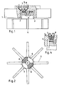
- the water flow meter has a pressure chamber, of which a wall 1 is shown. In a receptacle 2 of the wall 1, a pin 3 of an impeller 4 is mounted. The other walls and the connecting pieces of the pressure chamber are not shown.
- the water flow meter with the impeller 4 corresponds to the usual design.
- the end face 5 of the pin 3 there are a plurality of reflection coverings 6 in the form of sector sections.
- An infrared light barrier with a transmitting diode 7 and a receiving transistor 8 is aligned with the circular path of the reflection coatings 6.
- the transmitting diode 7 and the receiving transistor 8 are accommodated in an insert body 9.
- the insert body 9 is installed pressure-tight in the wall 1 of the pressure chamber.
- the reflection coatings can also be arranged elsewhere on the impeller, for example on the tips of the blades.
- Another infrared light barrier can be provided offset in the circumferential direction. This enables detection of the direction of rotation. In addition, vibrations in the hydraulic system do not lead to incorrect measurements.
- Fig. 3 shows an overall view of a heat meter with the water meter and the evaluation circuit.
- the optical transmitter diode 7 of the water flow meter is excited with pulses of 3 ⁇ s pulse width and a frequency of 128 Hz. These pulses are generated in the microprocessor 10 and shaped in a pulse shaper 11.
- the pulse mode serves to protect the electrical battery, so that long battery operation can be achieved for more than six years.
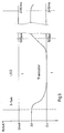
- the receiving transistor 8 is very sensitive to light, but has a low operating frequency.
- the narrow, high-energy transmit pulse switches through the receive transistor with a delay. This switch-on state then remains longer.
- the transmitter diode LED is excited with narrow pulses with a pulse width of 2 - 20 ⁇ s, preferably 3 - 5 ⁇ s and a pulse interval of 2 - 10 ms, corresponding to 500 - 100 Hz.
- the phototransistor has a delayed response and switching through to the line status and a pulse extension of up to 500 ms. This enables secure signal processing.
- the signals of the multiple light barriers are linked in a logic logic 12 in order to recognize the direction of rotation and to rule out faults.
- Temperature sensors 13 enable a measurement of the amount of heat by the microprocessor 10.
- a display 14 completes the arrangement.
- the insert body comprises light guides 14.
- the transmitting diode 7 and the receiving transistor 8 are located outside. You are therefore always accessible.
Landscapes
- Physics & Mathematics (AREA)
- Fluid Mechanics (AREA)
- General Physics & Mathematics (AREA)
- Measuring Volume Flow (AREA)
- Paper (AREA)
- Optical Transform (AREA)
Applications Claiming Priority (4)
| Application Number | Priority Date | Filing Date | Title |
|---|---|---|---|
| DE19539080 | 1995-10-20 | ||
| DE19539080 | 1995-10-20 | ||
| DE19543361 | 1995-11-21 | ||
| DE19543361A DE19543361C2 (de) | 1995-10-20 | 1995-11-21 | Wassermengenzähler |
Publications (3)
| Publication Number | Publication Date |
|---|---|
| EP0769681A2 true EP0769681A2 (fr) | 1997-04-23 |
| EP0769681A3 EP0769681A3 (fr) | 1997-11-26 |
| EP0769681B1 EP0769681B1 (fr) | 1998-09-02 |
Family
ID=26019639
Family Applications (1)
| Application Number | Title | Priority Date | Filing Date |
|---|---|---|---|
| EP96116454A Expired - Lifetime EP0769681B1 (fr) | 1995-10-20 | 1996-10-15 | Compteur d'eau |
Country Status (3)
| Country | Link |
|---|---|
| EP (1) | EP0769681B1 (fr) |
| AT (1) | ATE170625T1 (fr) |
| DK (1) | DK0769681T3 (fr) |
Cited By (4)
| Publication number | Priority date | Publication date | Assignee | Title |
|---|---|---|---|---|
| WO2005043091A1 (fr) * | 2003-11-02 | 2005-05-12 | S.F.M. Sophisticated Flow Meters Ltd. | Capteur de consommation de fluides utilisant un impulseur rotatif |
| EP2270438A3 (fr) * | 2009-07-04 | 2014-01-29 | QUNDIS GmbH | Débitmètre |
| CN110260933A (zh) * | 2019-07-03 | 2019-09-20 | 上海在田环境科技有限公司 | 无磁化水管流量检测结构、智能水表及管网流量监测系统 |
| WO2022013241A1 (fr) * | 2020-07-17 | 2022-01-20 | Commissariat A L'energie Atomique Et Aux Energies Alternatives | Système à rotor de mesure du débit d'un fluide comportant du liquide, et équipement associé |
Families Citing this family (2)
| Publication number | Priority date | Publication date | Assignee | Title |
|---|---|---|---|---|
| CN106643952A (zh) * | 2017-01-13 | 2017-05-10 | 南安市威速电子科技有限公司 | 一种智能远传液封光电直读水表 |
| CN110260932A (zh) * | 2019-07-03 | 2019-09-20 | 上海在田环境科技有限公司 | 无磁流量计结构及其智能水表 |
Family Cites Families (4)
| Publication number | Priority date | Publication date | Assignee | Title |
|---|---|---|---|---|
| DE2715239A1 (de) * | 1977-04-05 | 1978-10-12 | Georg Aigner | Durchflusszaehler fuer fluessigkeiten |
| DE3608807A1 (de) * | 1986-03-15 | 1987-09-17 | Wolfgang Hopf | Stellungsgeber und dessen verwendung |
| WO1988002545A1 (fr) * | 1986-10-03 | 1988-04-07 | Conax Buffalo Corporation | Appareil de protection a fibre optique |
| US5542302A (en) * | 1995-01-24 | 1996-08-06 | Mcmillan Company | Turbine wheel flow measuring transducer |
-
1996
- 1996-10-15 AT AT96116454T patent/ATE170625T1/de not_active IP Right Cessation
- 1996-10-15 EP EP96116454A patent/EP0769681B1/fr not_active Expired - Lifetime
- 1996-10-15 DK DK96116454T patent/DK0769681T3/da active
Cited By (5)
| Publication number | Priority date | Publication date | Assignee | Title |
|---|---|---|---|---|
| WO2005043091A1 (fr) * | 2003-11-02 | 2005-05-12 | S.F.M. Sophisticated Flow Meters Ltd. | Capteur de consommation de fluides utilisant un impulseur rotatif |
| EP2270438A3 (fr) * | 2009-07-04 | 2014-01-29 | QUNDIS GmbH | Débitmètre |
| CN110260933A (zh) * | 2019-07-03 | 2019-09-20 | 上海在田环境科技有限公司 | 无磁化水管流量检测结构、智能水表及管网流量监测系统 |
| WO2022013241A1 (fr) * | 2020-07-17 | 2022-01-20 | Commissariat A L'energie Atomique Et Aux Energies Alternatives | Système à rotor de mesure du débit d'un fluide comportant du liquide, et équipement associé |
| US12281920B2 (en) | 2020-07-17 | 2025-04-22 | Commissariat A L'energie Atomique Et Aux Energies Alternatives | Rotor system for measuring the flow rate of a fluid comprising a liquid, and associated equipment |
Also Published As
| Publication number | Publication date |
|---|---|
| DK0769681T3 (da) | 1999-06-07 |
| EP0769681A3 (fr) | 1997-11-26 |
| ATE170625T1 (de) | 1998-09-15 |
| EP0769681B1 (fr) | 1998-09-02 |
Similar Documents
| Publication | Publication Date | Title |
|---|---|---|
| DE2942421C2 (fr) | ||
| EP2872781B1 (fr) | Pompe centrifuge avec débitmètre à ultrasons | |
| DE102007007079B4 (de) | Detektionsvorrichtung und Motorsteuereinheit | |
| EP0769681B1 (fr) | Compteur d'eau | |
| DE19543361C2 (de) | Wassermengenzähler | |
| DE102009053339A1 (de) | Gasturbinentriebwerk mit einer Anordnung zur Messung der Wellendrehgeschwindigkeit | |
| EP2087322B1 (fr) | Volumetre pour substances en ecoulement equipe d'un dispositif compteur et d'une unite arithmetique couples selectivement | |
| EP0355144B1 (fr) | Transducteur combine de vitesse/temperature | |
| US20040231433A1 (en) | Flow meter | |
| DE2502599A1 (de) | Durchflussmesser mit einem rotor | |
| DE10142751A1 (de) | Vorrichtung bei einem Antrieb und Verfahren für die Vorrichtung | |
| EP0031317A1 (fr) | Appareil de mesure de la quantité d'un milieu caloporteur circulant dans un conduit | |
| DE3521188A1 (de) | Heizkoerper-ventil | |
| DE10214418A1 (de) | Volumenzähler zum Messen eines Flüssigkeitsvolumens | |
| DE3310239C3 (de) | Verfahren zum berührungslosen Messen der Drehzahl eines Flügelrades in einem Fluidzähler | |
| DE4308782C2 (de) | Sanitärelement zum Einschrauben in eine Leitung | |
| DE3844294C2 (fr) | ||
| DE2522163A1 (de) | Waermemengen-messgeraet | |
| DE3841275A1 (de) | Impulsgebereinrichtung fuer mengenzaehler | |
| DE4126733C2 (de) | Verfahren und Vorrichtung zum Nachweis der Verschmutzung des eintrittsseitigen Luftfilters eines Lüfters | |
| DE102007060544B4 (de) | Erfassungsvorrichtung für einen Induktionszähler, Induktionszähler sowie Verfahren zum Ablesen eines Induktionszählers | |
| WO2008135182A2 (fr) | Mesure de vitesse de rotation sans contact | |
| EP0933619A1 (fr) | Procédé et dispositif à mesure et correction continue d'un débit à une température de référence | |
| GB2123557A (en) | Flow meter measurement techniques | |
| DE102005021000B4 (de) | Meßgerät |
Legal Events
| Date | Code | Title | Description |
|---|---|---|---|
| PUAI | Public reference made under article 153(3) epc to a published international application that has entered the european phase |
Free format text: ORIGINAL CODE: 0009012 |
|
| AK | Designated contracting states |
Kind code of ref document: A2 Designated state(s): AT CH DE DK FI FR LI SE |
|
| PUAL | Search report despatched |
Free format text: ORIGINAL CODE: 0009013 |
|
| AK | Designated contracting states |
Kind code of ref document: A3 Designated state(s): AT CH DE DK FI FR LI SE |
|
| GRAG | Despatch of communication of intention to grant |
Free format text: ORIGINAL CODE: EPIDOS AGRA |
|
| 17P | Request for examination filed |
Effective date: 19980107 |
|
| GRAG | Despatch of communication of intention to grant |
Free format text: ORIGINAL CODE: EPIDOS AGRA |
|
| GRAH | Despatch of communication of intention to grant a patent |
Free format text: ORIGINAL CODE: EPIDOS IGRA |
|
| 17Q | First examination report despatched |
Effective date: 19980305 |
|
| GRAH | Despatch of communication of intention to grant a patent |
Free format text: ORIGINAL CODE: EPIDOS IGRA |
|
| GRAA | (expected) grant |
Free format text: ORIGINAL CODE: 0009210 |
|
| AK | Designated contracting states |
Kind code of ref document: B1 Designated state(s): AT CH DE DK FI FR LI SE |
|
| REF | Corresponds to: |
Ref document number: 170625 Country of ref document: AT Date of ref document: 19980915 Kind code of ref document: T |
|
| REG | Reference to a national code |
Ref country code: CH Ref legal event code: EP |
|
| REF | Corresponds to: |
Ref document number: 59600506 Country of ref document: DE Date of ref document: 19981008 |
|
| ET | Fr: translation filed | ||
| REG | Reference to a national code |
Ref country code: DK Ref legal event code: T3 |
|
| PLBE | No opposition filed within time limit |
Free format text: ORIGINAL CODE: 0009261 |
|
| STAA | Information on the status of an ep patent application or granted ep patent |
Free format text: STATUS: NO OPPOSITION FILED WITHIN TIME LIMIT |
|
| 26N | No opposition filed | ||
| PGFP | Annual fee paid to national office [announced via postgrant information from national office to epo] |
Ref country code: FR Payment date: 19991008 Year of fee payment: 4 |
|
| PGFP | Annual fee paid to national office [announced via postgrant information from national office to epo] |
Ref country code: SE Payment date: 19991021 Year of fee payment: 4 Ref country code: FI Payment date: 19991021 Year of fee payment: 4 Ref country code: DK Payment date: 19991021 Year of fee payment: 4 |
|
| PGFP | Annual fee paid to national office [announced via postgrant information from national office to epo] |
Ref country code: AT Payment date: 19991025 Year of fee payment: 4 |
|
| PGFP | Annual fee paid to national office [announced via postgrant information from national office to epo] |
Ref country code: DE Payment date: 19991230 Year of fee payment: 4 |
|
| PG25 | Lapsed in a contracting state [announced via postgrant information from national office to epo] |
Ref country code: FI Free format text: LAPSE BECAUSE OF NON-PAYMENT OF DUE FEES Effective date: 20001015 Ref country code: DK Free format text: LAPSE BECAUSE OF NON-PAYMENT OF DUE FEES Effective date: 20001015 Ref country code: AT Free format text: LAPSE BECAUSE OF NON-PAYMENT OF DUE FEES Effective date: 20001015 |
|
| PG25 | Lapsed in a contracting state [announced via postgrant information from national office to epo] |
Ref country code: SE Free format text: THE PATENT HAS BEEN ANNULLED BY A DECISION OF A NATIONAL AUTHORITY Effective date: 20001030 |
|
| PG25 | Lapsed in a contracting state [announced via postgrant information from national office to epo] |
Ref country code: LI Free format text: LAPSE BECAUSE OF NON-PAYMENT OF DUE FEES Effective date: 20001031 Ref country code: CH Free format text: LAPSE BECAUSE OF NON-PAYMENT OF DUE FEES Effective date: 20001031 |
|
| REG | Reference to a national code |
Ref country code: DK Ref legal event code: EBP |
|
| REG | Reference to a national code |
Ref country code: CH Ref legal event code: PL |
|
| EUG | Se: european patent has lapsed |
Ref document number: 96116454.8 |
|
| PG25 | Lapsed in a contracting state [announced via postgrant information from national office to epo] |
Ref country code: FR Free format text: LAPSE BECAUSE OF NON-PAYMENT OF DUE FEES Effective date: 20010629 |
|
| PG25 | Lapsed in a contracting state [announced via postgrant information from national office to epo] |
Ref country code: DE Free format text: LAPSE BECAUSE OF NON-PAYMENT OF DUE FEES Effective date: 20010703 |
|
| REG | Reference to a national code |
Ref country code: FR Ref legal event code: ST |