EP0769685A2 - Système de surveillance d'un niveau prédéterminé d'un fluide dans un récipient - Google Patents
Système de surveillance d'un niveau prédéterminé d'un fluide dans un récipient Download PDFInfo
- Publication number
- EP0769685A2 EP0769685A2 EP96116317A EP96116317A EP0769685A2 EP 0769685 A2 EP0769685 A2 EP 0769685A2 EP 96116317 A EP96116317 A EP 96116317A EP 96116317 A EP96116317 A EP 96116317A EP 0769685 A2 EP0769685 A2 EP 0769685A2
- Authority
- EP
- European Patent Office
- Prior art keywords
- container wall
- measuring point
- piezoelectric element
- arrangement according
- container
- Prior art date
- Legal status (The legal status is an assumption and is not a legal conclusion. Google has not performed a legal analysis and makes no representation as to the accuracy of the status listed.)
- Granted
Links
Images



Classifications
-
- G—PHYSICS
- G01—MEASURING; TESTING
- G01F—MEASURING VOLUME, VOLUME FLOW, MASS FLOW OR LIQUID LEVEL; METERING BY VOLUME
- G01F23/00—Indicating or measuring liquid level or level of fluent solid material, e.g. indicating in terms of volume or indicating by means of an alarm
- G01F23/22—Indicating or measuring liquid level or level of fluent solid material, e.g. indicating in terms of volume or indicating by means of an alarm by measuring physical variables, other than linear dimensions, pressure or weight, dependent on the level to be measured, e.g. by difference of heat transfer of steam or water
- G01F23/28—Indicating or measuring liquid level or level of fluent solid material, e.g. indicating in terms of volume or indicating by means of an alarm by measuring physical variables, other than linear dimensions, pressure or weight, dependent on the level to be measured, e.g. by difference of heat transfer of steam or water by measuring the variations of parameters of electromagnetic or acoustic waves applied directly to the liquid or fluent solid material
- G01F23/296—Acoustic waves
- G01F23/2961—Acoustic waves for discrete levels
-
- Y—GENERAL TAGGING OF NEW TECHNOLOGICAL DEVELOPMENTS; GENERAL TAGGING OF CROSS-SECTIONAL TECHNOLOGIES SPANNING OVER SEVERAL SECTIONS OF THE IPC; TECHNICAL SUBJECTS COVERED BY FORMER USPC CROSS-REFERENCE ART COLLECTIONS [XRACs] AND DIGESTS
- Y10—TECHNICAL SUBJECTS COVERED BY FORMER USPC
- Y10S—TECHNICAL SUBJECTS COVERED BY FORMER USPC CROSS-REFERENCE ART COLLECTIONS [XRACs] AND DIGESTS
- Y10S367/00—Communications, electrical: acoustic wave systems and devices
- Y10S367/908—Material level detection, e.g. liquid level
Definitions
- the invention relates to an arrangement for monitoring a predetermined level of a liquid in a container with an ultrasonic transducer, which is mounted on a measuring point at the level of the level to be monitored on the outside of the container wall and which, when excited by an AC voltage pulse, has a predetermined transmission frequency Transmits ultrasonic transmission pulse to the container wall and converts ultrasonic vibrations, which are generated by reflected echo pulses, into electrical reception signals, which are transmitted to an evaluation circuit which, based on the occurrence or absence of echo signals, determines whether the measuring point is covered by the liquid or not .
- the monitoring of the fill level is based on the following phenomena: If the measuring point is covered by the liquid, ultrasound waves are emitted from the container wall due to the ultrasound transmission pulse generated by the ultrasound transducer radiated into the liquid, which spread in the liquid and, after reflection on the opposite container wall, return as an echo signal to the location of the container wall at which the ultrasonic transducer is mounted. The ultrasonic vibrations of the container wall generated by the echo signal are converted by the ultrasonic transducer into an electrical AC voltage signal, which is fed to the evaluation circuit.
- the evaluation circuit thus receives one electrical echo pulse at a time interval after the transmission of the transmission pulse, which corresponds to the transit time of the ultrasonic waves in the liquid to the opposite container wall and back. From the appearance of the echo pulse at this time interval after the transmission pulse, the evaluation circuit thus recognizes that the measuring point is covered by the liquid and indicates that the level to be monitored has been reached or exceeded. On the other hand, if the measuring point is not covered by the liquid but is in contact with the air above the liquid level, the evaluation circuit does not receive an echo pulse at the same time interval after the transmission of a transmission pulse. This is primarily due to the fact that, due to the large difference in the acoustic impedances of the container wall and the air, the emission of ultrasonic waves into the air is very low.
- the evaluation circuit concludes that the measuring point is not covered by the liquid and indicates that the level to be monitored in the container has not been reached.
- This known method is not fail-safe.
- the absence of the echo pulses does not show whether this is really due to the fact that the level to be monitored has not been reached or whether there is another cause. For example, even if circuit parts fail, a line is interrupted and similar errors, no echo pulses are received, even if the measuring point is covered by the liquid. It can also happen that the propagation conditions for the ultrasonic waves are temporarily disturbed, for example by the formation of air bubbles during a filling process. In such cases, no echo pulses would be received either, and the evaluation circuit would indicate that the level to be monitored in the container had not been reached, even when the measuring point is actually covered by the liquid.
- the object of the invention is to provide an arrangement of the type specified at the outset, which has a high level of error security.
- this is achieved in that the ultrasound transducer is excited with a transmission frequency which is equal to the thickness resonance frequency of the container wall, and in the evaluation circuit also the ultrasound vibrations generated by the oscillation of the container wall after the end of the transmission pulse are evaluated in order to determine whether the measuring point is covered by the liquid or not.
- the fact is evaluated that the thickness vibrations of the container wall do not stop immediately with the end of the transmission pulse, but gradually subside due to the oscillation of the container wall.
- the duration of the ringing depends on whether the measuring point on the container wall is covered by the liquid or not. When the measuring point is covered, the vibrations are dampened more than when the measuring point is uncovered, so that they decay more quickly.
- the reverberation of the container wall is converted by the ultrasonic transducer into an electrical AC voltage signal, which is also fed to the evaluation circuit.
- the evaluation circuit determines at a certain time interval after the end of the transmission pulse that the signal originating from the ringing is missing, it recognizes from this that the measuring point is covered by the liquid, that is to say the level to be monitored has been reached or exceeded. If, on the other hand, the signal from the ringing is present at the same time interval after the end of the transmission pulse, it recognizes from this that the measuring point is not covered by the liquid, that is to say the level to be monitored has not been reached.
- the two signals evaluated by the evaluation circuit are to a certain extent complementary to one another: if the measuring point is covered, the echo signal is present, but the ringing signal is missing; if the measuring point is not covered, the ringing signal is present, but the echo signal is missing.
- Fig. 1 shows a container 10 which is filled to a height H with a liquid 11.
- the height H at which the surface of the liquid 11 is located above the bottom of the container 10 is the current filling level in the container.
- the fill level should not exceed a maximum height H max and a minimum height H min .
- Each of these limit values of the fill level is also called "limit level".
- a fill level sensor 13 is attached to the outside of the container wall 12 and is connected to an excitation and evaluation electronics 14.
- a fill level sensor 15 is attached to the outside of the container wall 12 and is connected to an excitation and evaluation electronics 16.
- Each of the two sensors 13 and 15 is designed so that it can be used to determine through the container wall 12 whether or not the liquid 11 in the container 10 is at the level of the sensor 13 or 15.
- each of the two sensors 13 and 15 is designed as an ultrasonic sensor, which is capable of emitting an ultrasonic pulse toward the container wall 12 when excited by an electrical AC voltage pulse, which is supplied by the associated excitation and evaluation circuit 14 or 16 and convert received ultrasound signals into electrical AC signals that are transmitted to electronics 14 and 16, respectively.
- Electronics 14 and 16 evaluate the received signals and emit a signal at the output which indicates whether the fill level in container 10 is above or below the limit level to be monitored. For this determination it is therefore not necessary to break through the container wall 14 or the sensor into the interior of the container 10 bring in. For this reason, the sensors 14 and 16 are also not in direct contact with the liquid 11.
- the two sensors 13 and 15 and the associated electronics 14 and 16 are of completely identical design. Therefore, only the sensor 13 and the electronics 14 are described in detail below. This description applies in the same way to the sensor 15 and the electronics 16.
- FIG. 2 shows a perspective view of the sensor 13, and FIGS. 3 and 4 show sectional views of the sensor 13 attached to the container wall 12.
- FIG. 3 shows a longitudinal section of the sensor 13 in the event that the container wall is flat, and 4 shows a cross section through the sensor in the event that the container wall is cylindrical.
- the sensor shown in FIG. 2 consists of a sensor block 20, which contains all components of the ultrasonic sensor and the excitation and evaluation electronics, and an adapter 21, which is used to attach the sensor block 20 to containers of different shapes and sizes and from different materials fasten.
- the sensor block 20 has a sensor housing 22 which is closed by a cover 23 which is fastened on the sensor housing 22 by means of screws 24.
- the sensor block 20 is fastened to the adapter 21 by means of screws 26 which pass through bores in projections 27 on the narrow sides of the sensor housing 22 and are screwed into threaded bores in corresponding projections 28 on the adapter 21. After loosening the two screws 26, the complete sensor block can be removed from the adapter 21 attached to the container wall 12.
- the adapter 21 is fastened in a suitable manner without the sensor block 20 at the desired location on a container wall, and then the sensor block 20 with the ready-to-use mounted ultrasonic sensor is placed on the adapter 21 and fastened by means of the screws 26.
- a connection block 29 projecting laterally from the sensor housing 22 enables the electronics housed in the sensor housing 22 to be connected to external connection conductors.
- the adapter 21 is a molded plastic part which essentially consists of a plate 30, the outline of which corresponds to the outline of the sensor housing 22, that is to say is rectangular in the example shown.
- a frame 31 is formed around the circumference of the plate 30 and is provided on the side facing the container wall with a groove 32 into which a seal 33 is inserted.
- the frame 31 has a constant height on the long sides of the adapter 21, which in the case of a cylindrical container 10 lie along the surface lines on the container wall 12.
- the frame 31 On the transverse sides, which in the case of a cylindrical container 10 abut the container wall 12 along the circumference, the frame 31 has an arcuate recess 34, as can be seen in FIG. 2 on the front transverse side.
- the radius of curvature of the recess 34 corresponds to the radius of the container wall 12 of the container 10 with the smallest diameter to which the adapter 21 is to be attached. If the ultrasonic sensor 13 is intended for containers whose nominal width (diameter) is at least 200 mm, the radius of curvature of the recess 34 is therefore 100 mm.
- the seal 33 is designed such that its sealing surface intended for contact with the container wall lies in one plane when the adapter 21 has not yet been attached to the container wall 12 and the seal 33 has therefore not yet been deformed.
- the seal 33 has a constant height along the longitudinal sides of the frame 31, while its height in the region of each transverse side increases in the shape of an arc toward the center in accordance with the shape of the recess 34.
- the seal 33 is preferably with two sealing lips 35 formed between which there is a notch 36.
- the sealing lips 35 are relatively low along the long sides of the frame 31 (FIG. 4), and the depth of the notch 36 is correspondingly small there.
- the height of the sealing lips 35 and the depth of the notch 36 increase to the same extent as the height of the seal 33 have greatest depth, the sealing lips 35 have their greatest height and the notches 36 have their greatest depth in this sectional view.
- the sealing lips 35 in the region of the recesses 34 are compressed to the same extent as in the region of the straight longitudinal sides of the frame 31, that is to say relatively little. If, on the other hand, the adapter 21 is attached to a cylindrical container wall 12 (FIG. 4), the sealing lips in the region of the recesses 34 are deformed more than in the region of the straight longitudinal sides of the frame 31, and the more so, the smaller the radius of curvature of the container wall 12 is. This greater deformation is made possible by the greater height of the sealing lips 35 and the greater depth of the notch 36 in this area. In all cases, however, the sealing lips 35 lie sealingly against the container wall 12 along the entire circumference of the adapter 21.
- FIG. 3 shows a first possibility of fastening the adapter 21 to the container wall 12: threaded bolts 37 are welded to the container wall 12, which protrude through the openings of bushings 38, which are integrally formed on the plate 30 of the adapter 21. Nuts 39 are screwed onto the ends of the threaded bolts 37 which protrude from the bushes 38 and which clamp the plate 30 against the container wall 12 by compressing the seal 31. If necessary, spacers projecting downward from the plate 30 toward the container wall 12 can be formed be, which determine a defined distance of the plate 30 from the container wall 12 and thereby a defined position of the adapter 21 with respect to the container wall 12.
- FIG. 4 Another type of attachment of the adapter 21 to the container wall 12 is shown in the left half of FIG. 4.
- a leg of an angle piece 41 made of strong sheet metal is inserted into a lateral slot 40, which is provided in the middle of each long side of the adapter 21, and is fastened therein by means of a screw 42.
- the other leg of the angle piece 40 which is bent upwards at right angles, is bent at the end in a hook shape.
- This hook-shaped bent end comprises a rail 43 which is welded to the container wall 12, and it is clamped to the rail 43 by means of at least one screw 44.
- This type of fastening makes it possible in a simple manner to determine the location at which the sensor 13 is to be attached to the container 10 and, if necessary, to change it subsequently by moving the adapter 21 along the rail 38.
- the hooking of the tension band 49 at the upper ends of the upwardly bent legs of the angle pieces 41 has the consequence that the points of application of the force exerted by the tension band 49 on the adapter 21 are relatively high. This is advantageous because, particularly in the case of containers with a large radius of curvature, the force component pressing against the container increases significantly with the height of the point of application.
- the threaded bolts 37 or the rails 43 can also be fastened to the container wall 12 by gluing instead of by welding. This type of attachment of the adapter 21 is then also suitable for plastic containers.
- the sensor housing 22 is divided into two rooms 46 and 47 by a transverse wall 45.
- the excitation and evaluation electronics 14 are accommodated, which in the usual way consist of electronic components which are mounted on a circuit board 48.
- the components of the ultrasonic sensor 13 are mounted in the inner space 47 facing the container wall 12 and the adapter 21.
- this includes an electroacoustic transducer 50, which serves to convert an AC voltage pulse supplied by the excitation and evaluation circuit into an ultrasound pulse that is transmitted to the container wall 12, and to convert ultrasound vibrations that it receives from the container wall 12 into an electrical AC voltage , which is transmitted to the excitation and evaluation circuit.
- the electroacoustic transducer 50 is shown in more detail in FIG. 5.
- an active component it contains a piezoelectric element 51, which in a known manner is a disk made of a piezo crystal, on both sides of which metallizations are applied, which serve as electrodes.
- the piezo crystal When an AC voltage is applied to the electrodes, the piezo crystal is excited to mechanical vibrations at the frequency of the AC voltage, and when mechanical vibrations are transmitted to the piezo crystal, it generates an AC voltage at the frequency of the mechanical vibrations between the electrodes.
- the electrodes are not shown because they are small Thickness of the metallization compared to the thickness of the piezo crystal are not visible.
- the piezoelectric element 51 is arranged inside a pot-shaped transducer housing 52 and lies on the bottom 53 of the transducer housing 52, which at the same time forms the membrane of the ultrasound transducer 50.
- the converter housing 52 is made of plastic.
- a circuit board 54 On the side of the piezoelectric element 51 facing away from the membrane 53, a circuit board 54 is arranged which carries the components of a circuit which is used to couple the piezoelectric element 51 to the excitation and evaluation electronics 14.
- the circuit board 54 is located at a distance from the piezoelectric element 51, and the space between the circuit board 54 and the piezoelectric element 51 is filled with a potting compound 55, which is filled in in the liquid state and then solidifies.
- the side of the piezoelectric element 51 facing away from the membrane 53 is covered with a disk 56 made of a closed-cell foam which prevents the potting compound 55 from coming into direct contact with the piezoelectric element 51.
- the space above the circuit board 54 is also filled with the potting compound 55 to such a height that all circuit components mounted on the circuit board 54 are embedded in the potting compound 55.
- the potting compound 55 is prescribed for reasons of explosion protection. It also has the effect of damping the ultrasound waves which are emitted on the side opposite the membrane 53.
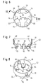
- a mounting sleeve 60 is provided, which is shown in more detail in FIGS. 6, 7 and 8.
- the mounting sleeve 60 is a molded body made of plastic, which is shown in FIG. 6 in plan view, in FIG. 7 in longitudinal section along the broken line AA of FIG. 6 and in FIG. 8 in perspective View is shown.
- the mounting sleeve 60 has a wider cylindrical portion 61, a narrower cylindrical portion 62 of smaller diameter, and a conical portion 63 between the two cylindrical portions 61 and 62.
- the outer diameter of the wider cylindrical portion 61 corresponds to the inner diameter of the cup-shaped converter housing 52, and the inner diameter of the narrower cylindrical section 62 corresponds to the diameter of the piezoelectric element 51.
- the narrower cylindrical section 62 and the conical transition section 63 are divided into six segments 64 by cutouts.
- a radially inwardly projecting paw 65 is formed on each segment 64 at the transition between the cylindrical section 61 and the conical section 63.
- a stop nose 66 is formed below each paw 65, which extends downward only over part of the height of the cylindrical section 62 and projects only slightly radially inwards.
- a shoulder 67 is formed at the transition between the conical section 63 and the wider cylindrical section 61.
- an elastic catch 68 is formed at two diametrically opposite locations by cutouts, the free end of which projects slightly inwards and lies at a distance from the shoulder 67 which corresponds to the thickness of the circuit board 54.
- a rib 69 formed on the circumference of the wider cylindrical section 61 engages in a corresponding groove in the converter housing 52, as a result of which the mounting sleeve 60 in the converter housing 52 is secured against rotation.
- the described design of the mounting sleeve 60 allows a simple, quick and precise assembly of the components of the ultrasonic transducer 50 outside the transducer housing 52.
- the piezoelectric element 51 with the disk 56 made of closed-cell foam placed thereon is inserted from below into the narrower cylindrical section 62 until the piezoelectric element 51 at the ends of the stop lugs 66 triggers.
- the radial and axial position of the piezoelectric element 51 in the mounting sleeve 60 is precisely defined.
- the diameter of the foam disc 56 is slightly smaller than the diameter of the piezoelectric element 51 and corresponds to the distance between two diametrically opposite stop lugs 66, and the thickness of the foam disc 56 corresponds to the height of the stop lugs 66.
- the paws 65 lie on the top of the foam disc 56 when the piezoelectric element 51 is inserted as far as it will go into the mounting sleeve 60, and the stop lugs 66 rest against the circumference of the foam disk 56.
- the radial and axial position of the foam disc 56 in the mounting sleeve 60 is precisely defined, and the foam disc 56 is held in close contact with the top surface of the piezoelectric element 51 by the paws 65.
- the circuit board 54 is circular with a diameter that corresponds to the inner diameter of the wider cylindrical portion 61 of the mounting sleeve 60. It is inserted into the wider cylindrical section 61 from above until it rests on the shoulder 67. During insertion, the catches 68 are pushed outward from the peripheral edge of the circuit board 54 until the peripheral edge of the circuit board 54 has passed the ends of the catches 68. Then, the catches 68 protrude inward again due to their elasticity, so that they grip over the top of the circuit board 54 and hold it on the shoulder 67. As a result, the circuit board 54 is also fixed in the mounting sleeve 60 in the axial and radial directions.
- the mounting sleeve 60 is ready for installation in the pot-shaped converter housing 52.
- a drop of a thermosetting adhesive is first applied to the bottom 53 of the converter housing 52, and then the mounting sleeve 60 is inserted into the converter housing 52 until the piezoelectric element 51 touches the bottom 53.
- the adhesive is distributed in a thin layer between the facing surfaces of the piezoelectric element 51 and the bottom 53.
- the adhesive is then cured by heating, the mounting sleeve 60 being weighted down in order to obtain a defined adhesive layer.
- the adhesive layer ensures the contact between the piezoelectric element 51 and the membrane of the ultrasonic transducer 50 formed by the bottom 53 and prevents the formation of an air layer between these parts.
- potting compound 55 is poured into the mounting sleeve 60 from above.
- This potting compound flows through openings provided for this purpose in the circuit board 54 and also into the space between the circuit board 54 and the foam disk 56.
- the foam disk 56 prevents the potting compound 55 from coming into contact with the upper side of the piezoelectric element 51.
- the paws 65 which press the edge of the foam disc 56 onto the upper side of the piezoelectric element 51, prevent casting compound 55 from creeping between the foam disc 56 and the piezoelectric element 51.
- a mounting part 70 with a flange 71, on which a guide bush 72 is formed, is used to mount the pot-shaped converter housing 52 in the sensor housing 22.
- the converter housing 52 is inserted into the guide bush 72, the inside diameter of which corresponds to the outside diameter of the converter housing 52, so that the converter housing 52 is slidably mounted in the guide bush 72.
- the collar 57 on the converter housing 52 prevents the converter housing 52 from emerging from the guide bush 72.
- a spring cup 73 is inserted into the open end of the converter housing 52, which in turn has a collar 74 which is supported at the end of the converter housing 52.
- the spring cup 73 receives one end of a helical compression spring 75.
- a collar 76 runs around the edge of the flange 71, the inside diameter of which corresponds to the outside diameter of a support tube 77 formed on the transverse wall 45.
- a connecting line 78 which is soldered to the circuit board 54 and is intended for connecting the ultrasound transducer 50 to the excitation and evaluation electronics 16, is passed through a pipe socket projecting from the transverse wall 45 to the opposite side 79 performed.
- a sealing ring 80 is placed on the flange 71, to which the outer edge of an annular sleeve 81 is fastened, the inner edge of which is connected to an elastic ring 82 placed around the converter housing 52. Then the collar 76 is pushed over the support tube 77 and the flange 71 is fastened to the support tube 77 by means of screws 83 which are screwed into thickened wall sections of the support tube 77 and one of which is visible in FIG.
- the spring 75 is dimensioned such that it is compressed between the spring cup 73 and the transverse wall 45 to achieve a desired pretension when the holding part 70 is fastened to the carrier tube 77.
- the connecting line 78 can then be soldered to the connection points provided on the circuit board 48, and the outer space 41 can be filled with a casting compound almost up to the height of the pipe socket 79.
- the pipe socket 79 prevents the potting compound from flowing into the inner space 42.
- the sensor block 20 is thus assembled ready for operation, and it can be attached to the adapter 21.
- the guide bush 72 is inserted through an opening in the plate 30 of the adapter 21, so that the bottom of the transducer housing 72, ie the membrane 53 of the ultrasonic transducer 50, is placed against the outside of the container wall 12.
- the converter housing 52 is held by the container wall 12 so that it is pushed into the guide bush 72, whereby the spring 75 is further compressed.
- the membrane 23 is secured with a pressing force determined by the spring 75 against the container wall 12.
- FIGS. 3 and 4 A comparison of FIGS. 3 and 4 shows that the ultrasonic transducer 50 protrudes further from the guide bush 72 when the sensor 13 is attached to a flat container wall 12 (FIG. 3) than in the case of a curved container wall 12 (FIG. 4), but with in any case, the contact of the membrane 53 on the container wall 12 is ensured with a pressure force determined by the spring 75.
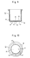
- the sectional view of the converter housing 52 in FIG. 9 reveals that a circumferential recess 85 is formed on the inside of the membrane 53 and surrounds the active membrane region 86 on which the piezoelectric element 51 rests.
- an adhesive is applied to the exposed surface of the piezoelectric element 51 before inserting the mounting sleeve 60 into the pot-shaped converter housing 52, which adhesive, if the Piezoelectric element 51 is pressed onto the active membrane area 86 when the mounting sleeve 60 is inserted, distributed between the mutually facing surfaces of these two parts.
- the annular recess 85 serves to absorb excess adhesive, which is displaced from the space between the piezoelectric element 51 and the active membrane region 86.
- a thermosetting adhesive is preferably used because it does not lose its properties even at higher operating temperatures.
- a series of projections 87 are formed on the outside of the membrane 53 and are arranged in a circular ring which approximately coincides with the circumference of the active membrane region 86 (FIG. 10).
- the projections 87 have the shape of round knobs in the example shown.
- the annular region 88 of the membrane 53 lying outside the ring of the projections 87 is somewhat recessed compared to the membrane surface 89 lying inside the ring.
- a recess 90 can be seen on the inside of the membrane 53, which serves to receive the soldering point, through which a connecting conductor is connected to the electrode of the piezoelectric element 51 resting on the membrane. This depression lies on the outside of the membrane 53 opposite a correspondingly enlarged projection 91.
- a coupling layer made of a material is introduced between the membrane 53 and the container wall 12, which prevents the formation of an air layer between the Prevents membrane 53 and the container wall 12 and results in a good acoustic coupling between the membrane and the container wall.
- the projections 87 which come into direct contact with the container wall 12, determine the thickness of the coupling layer.
- Suitable material for the coupling layer is, for example, the silicone gel known commercially under the name Wacker SilGel 612. This is a two-component silicone rubber that forms after the two components have been mixed by addition crosslinking very soft, gel-like vulcanizate solidified. After the two components have been mixed, this material is initially very thin, which is disadvantageous since there is a risk that it will drain off prematurely when it is applied to the membrane surface 89 before the membrane 53 is placed on the container wall 12.
- the silicone gel is therefore preferably reinforced by admixing glass fibers, for example in a proportion of 50% by volume.
- the glass fibers can have a diameter of 30 ⁇ m and a length of 400 ⁇ m.
- the glass fibers increase the viscosity of the silicone gel, which prevents premature drainage.
- the glass fibers also cause an increase in the acoustic impedance of the coupling layer, which is advantageous because it thereby approximates the acoustic impedance of the plastic membrane 53.
- the membrane For the good coupling between the membrane 53 and the container wall 12 achieved by the coupling layer, it is essential that the membrane consists of plastic, because the acoustic impedances of the plastic membrane and the coupling layer are of the same order of magnitude, so that no large jumps in impedance occur.
- This enables the Use of a relatively thick coupling layer.
- the thicker the coupling layer the better the thermal and mechanical stability of the sensor.
- the upper limit of the thickness of the coupling layer is that its thickness resonance should lie above the applied ultrasound frequency.
- the thickness of the coupling layer and thus the height of the projections can be approximately 0.2 mm.
- the entire converter housing 52 must consist of a plastic that is suitable for the membrane 53.
- An essential requirement for the material of the membrane is that the dynamic glass transition, i.e. the temperature at which the plastic changes from the crystalline phase to the amorphous phase should be above the highest operating temperature.
- Polyether ether ketone (PEEK) has proven to be particularly suitable.
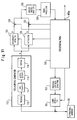
- FIG. 11 shows a simplified block diagram of the excitation and evaluation electronics 14.
- the ultrasound transducer 50 is symbolically represented by a circuit block.
- a control circuit 100 controls all functions of the various circuit components. This includes a frequency synthesis circuit 102 that generates an electrical AC voltage with the frequency that the ultrasound signal generated by the ultrasound transducer 50 is intended to have. This frequency is determined by a control signal which is applied by the control circuit 100 to a control input of the frequency synthesis circuit 102.
- the output of the frequency synthesis circuit 102 is connected to the signal input of a transmission pulse gate 104, which receives an opening pulse at its control input from the control circuit 100 each time the ultrasound transducer 50 is to generate an ultrasound pulse.
- the transmission pulse gate 104 is opened by the opening pulse, so that the AC voltage generated by the frequency synthesis circuit 102 is applied to the ultrasonic transducer 50 for the duration of the opening pulse.
- connection of the ultrasound transducer 50 is connected to the input of an envelope generator 110, which in cascade contains a high-pass 112, an amplifier 114, a rectifier 116 and a low-pass 118.
- the high pass 112 only allows frequencies above the lower operating frequency of the ultrasonic transducer 50 to pass through.
- Amplifier 114 amplifies the output of high pass 112 for easy rectification.
- the envelope signal of the AC voltage signal supplied by the ultrasonic transducer 50 is formed by the rectifier 116 and the downstream low-pass filter 118.
- An essential feature of the excitation and evaluation circuit of FIG. 11 is that the transmission frequency generated by the frequency synthesis circuit with which the ultrasound transducer 50 is excited is exactly equal to a thickness resonance frequency of the container wall 12 on which the ultrasound sensor 13 is mounted.
- This thickness resonance frequency can be the fundamental frequency of the thickness resonance or, in the case of thick container walls, for which this fundamental frequency would be too low, the second order of resonance.
- the diagrams in FIG. 12 show the envelope signals which are obtained under this condition at the output of the envelope generator 110.
- FIG. 12 shows the envelope signal H as a function of time t in the event that the level in the container 10 is above the level to be monitored by the ultrasonic sensor, so that the measuring point, ie the location of the container wall 12 at which the Ultrasonic sensor is mounted, is covered by the liquid 11. This corresponds to the state of sensor 15 in FIG. 1.
- Diagram B of FIG. 12 shows envelope signal H as a function of time t in the event that the fill level in container 10 is below the fill level to be monitored by the ultrasonic sensor, so that the measuring point is not covered by the liquid 11. This corresponds to the state of the sensor 13 in FIG. 1.
- Diagram A shows the transmission pulse S which begins at time t 0 and ends at time t 1 .
- the transmit pulse causes the container wall 12 at the point to which the ultrasonic transducer 50 transmits ultrasonic vibrations to be subjected to thickness vibrations with the natural resonance frequency, which gradually build up, as shown by the broken line.
- the transmit pulse should be so long that the thickness vibrations reach the stationary final state before the end of the transmit pulse.
- the thickness vibrations do not end immediately with the end of the transmission pulse at time t 1 , but they gradually subside due to the swinging of the container wall.
- the envelope curve signal H thus contains the envelope curve N of the oscillation of the container wall 12 following the end of the transmission pulse S.
- the container wall 12 is dampened at the oscillating point by the liquid from which it is covered, the decay takes place relatively quickly. so that it essentially ends at a time t 2 , which is relatively short after the time t 1 , and after this time t 2 there is practically no envelope signal caused by the ringing.
- the container wall vibrating in thickness resonance also emits ultrasonic waves into the interior of the container. Since the vibrating measuring point is covered by the liquid, the ultrasonic waves propagate in the liquid so that they reach the opposite container wall and are reflected there.
- the reflected ultrasound waves return as an echo signal to the location where the ultrasound sensor is mounted and are transmitted via the container wall to the ultrasound transducer 50, which converts them into an electrical signal that arrives at the input of the envelope generator 110. Therefore, appears in the envelope signal emitted by the envelope generator 110 Time t 5 is the envelope curve E of the echo signal reflected on the opposite container wall. It has been found that this echo signal with the optimum value is obtained when the transmission frequency corresponds to the thickness resonance frequency of the container wall.
- Diagram B of FIG. 12 also shows the transmission pulse S, which begins at time t 0 and ends at time t 1 , as well as the envelope N of the ringing of the container wall 12. Since the oscillating measuring point of the container wall 12 is not covered by the liquid, it is damped less than in the case of diagram A, so that the thickness resonance vibrations of the container wall subside more slowly. The envelope N of the reverberation therefore still has a considerable height at the time t 2 , in which it has practically disappeared when the measuring point is covered.
- the envelope signal H supplied by the envelope generator 110 is fed in parallel to an integrator 120 and a peak value detector 122.
- the integrator 120 is controlled by a control signal supplied by the control circuit 100 so that it sends the envelope signal H in a time window after each transmission of a transmission pulse S. F 1 integrated between times t 2 and t 3 .
- the peak value detector 122 is controlled by a control signal supplied by the control circuit 100 so that it determines the peak value of the envelope signal H in a time window F 2 between the times t 4 and t 6 , which contains the time t 5 of the echo signal E.
- the integration of the envelope curve signal H in the time window F 1 increases the certainty when determining whether a reverberation is present after the time t 2 or not, compared to a simple sampling of the envelope curve signal H at a time which lies behind the time t 2 .
- a comparison of the diagrams A and B in FIG. 12 reveals that the integral of the envelope signal H in the time window F 1 in the case of diagram B is considerably larger than in the case of diagram A, even if sporadic disturbances in the time window F in the latter case 1 should occur.
- the integrator 120 emits an analog signal I at the output, which indicates the value of the integral.
- the time window F 2 is necessary because the time t 5 of the echo signal E can vary due to different sound velocities in the liquid. Changes in the speed of sound can occur in the same liquid due to changes in temperature. Furthermore, different speeds of sound can exist when other liquids are filled into the container.
- the time window F 2 is chosen so that the echo signal is in this time window under all conditions.
- the peak value detector 122 emits an analog signal P at the output, which indicates the peak value (peak) of the envelope signal H determined in the time window F 2 .
- the output of the integrator 120 is connected to the input of an analog-digital converter 128 via a switch 124.
- the output of the peak value detector 122 is also connected to the input of the analog-to-digital converter 128 via a switch 126.
- the two switches 126 and 128 can be opened and closed by control signals provided by the control circuit 100.
- the output of the digital converter 128 is connected to a microprocessor 130.
- the level monitoring is therefore carried out with a high level of error security. As long as only one of the two signals I and P exceeds the assigned threshold value, it is certain that the monitored fill level is correctly determined. If neither of the two signals I and P exceeds the assigned threshold value, or if both signals I and P simultaneously exceed the assigned threshold, it can be seen that there is an error.
- the microprocessor 130 supplies the result of the signal evaluation to the control circuit 100, which accordingly emits a signal at an output 100a which indicates whether the fill level in the container is above or below the level to be monitored or whether there is a fault condition.
- the transmission frequency generated by the frequency synthesis circuit 102 must correspond as closely as possible to a thickness resonance frequency of the container wall 12.
- This thickness resonance frequency depends on the material and the thickness of the container wall.
- the evaluated thickness resonance frequency is between approximately 0.6 MHz and 2 MHz, for plastic containers with the same wall thickness between 0.3 MHz and 0.6 MHz.
- the thickness resonance frequency when the measuring point is covered is somewhat different from the thickness resonance frequency when the measuring point is uncovered.
- the thickness resonance frequency changes during operation, particularly as a function of the temperature.
- the thickness resonance frequency of the container wall is determined before the measuring arrangement is put into operation when the measuring point is covered and when it is uncovered, and is stored in the control circuit 100.
- These resonance frequencies correspond to the maximum peak signal P in the covered state or the maximum integral signal I in the uncovered state.
- the thickness resonance frequencies in a certain range are corrected in operation by the frequencies found during commissioning.
- the criterion for the correction of the frequency used for the integral measurement is a maximum integral signal I
- the criterion for the correction of the frequency used for the peak value measurement is a maximum peak value signal P. If the frequency values determined in this way are more than a certain tolerance threshold from the stored frequency values the stored frequency values are corrected accordingly.
- the measurement is preferably carried out in successive transmission periods alternately with one and the other stored thickness resonance frequency.
- the control circuit 100 causes the ultrasound transducer 50 to be excited with the transmission frequency which corresponds to the resonance frequency with the maximum integral signal I.
- the control circuit 100 opens the switch 126 so that the output signal P of the peak value detector 122 is not used in this transmission period. If the measuring point is actually not covered, the peak value detector 122 would not deliver a usable output signal in this transmission period anyway. If, on the other hand, the measuring point is covered, the output signal of the peak value detector 122 would not be optimal.
- the transmission frequency has the value at which the integrator 120 delivers the optimal output signal when the measuring point is actually not covered.
- the control circuit 100 causes the ultrasonic transducer 50 to be energized at the transmission frequency that corresponds to the resonance frequency with the maximum peak signal P, and opens the switch 124 while the switch 126 is closed.
- the output signal I of the integrator 120 is not used in this transmission period. If the measuring point is actually covered, the integrator 120 would not deliver a usable output signal in this transmission period anyway. On the other hand, if the measuring point is not covered, the output signal of the integrator 120 would not be optimal because it would not be recorded at the correct thickness resonance frequency.
- the transmission frequency in this transmission period has the value at which the peak value detector 122 delivers the optimal output signal when the measuring point is actually covered.
- microprocessor 130 receives from the integrator 120 in the uncovered state and from the peak value detector 122 in the covered state in each case usable (i.e. exceeding the assigned threshold value) output signals which have been obtained at the correct thickness resonance frequency.
- the monitoring of the fill level can be continued in each case with the aid of the other signal, by the faulty one Switch 224 or 226 assigned to the signal remains permanently open.
- the increased error safety explained above is then omitted, but the measuring arrangement still works with the same error security as known measuring arrangements. The same procedure can be followed if the detection of one of the two signals is not possible for a specific product. The measuring arrangement can therefore be used in a very versatile manner without design changes.
- the piezoelectric element 51 since the piezoelectric transducer 50 is excited with a thickness resonance frequency of the container wall 12, the piezoelectric element 51 must be designed in such a way that it works satisfactorily at the thickness resonance frequency used in each case.
- Disc-shaped piezoelectric elements show two vibration modes, namely thickness vibrations and radial vibrations with different resonance frequencies.
- the radial vibrations are not suitable for the application described because they are practically non-transferable via the plastic membrane 53 and the soft coupling layer, so that the energy of the radial vibrations can be regarded as a loss.
- a piezoelectric element 51 which consists of a porous piezoelectric ceramic with connectivity 3-3.
- Connectivity (English “connectivity”) was introduced by RE Newnham to characterize the structures of multi-phase solids and also applied to electro-ceramic composites (RE Newnham “Composite Electroceramics", Ferroelectrics 1986, Vol. 68, pp. 1-32 ).
- Connectivity describes the spatial directions in a three-dimensional rectangular coordinate system in which the components of each phase are continuously connected to each other.
- the number 0 means that the components of a phase are not connected to one another in any spatial direction
- the number 1 means that the components of a phase are connected to one another in only one spatial direction
- Connectivity 3-3 means that in the case of a two-phase solid, the components of each of the two Phases in all three spatial directions are continuously connected.
- a porous piezoelectric element 51 with the connectivity 3-3 largely eliminates all of the problems described above.
- the radial vibration modes are damped more than with conventional piezoelectric elements; the piezoelectric element behaves almost like a pure thickness transducer.
- the acoustic impedance is closer to that of the plastic membrane 53 and the coupling layer, which is introduced between the plastic membrane 53 and the container wall 12, whereby a better adaptation is achieved.
- the piezoelectric element is much broader than a conventional piezoelectric element; this makes it possible to cover the entire frequency range from 0.3 MHz to 2 MHz with three to four piezoelectric elements.
- the porosity of the piezoelectric element 51 requires some special measures, in particular with regard to the potting compound 55, with which the space on the membrane 53 facing away from the piezoelectric element 51 is filled.
- the encapsulation serves on the one hand to avoid cavities and to enclose the electrical and electronic components for reasons of explosion protection, and on the other hand for acoustic damping on the side of the piezoelectric element facing away from the membrane 53.
- potting would not be necessary for acoustic reasons; However, there remains the requirement to provide a potting for reasons of explosion protection.
- This requirement requires a potting compound that flows easily when filling, so that even small voids and gaps are filled; a low-viscosity silicone potting compound of the Sylgard 170 type is preferably used. This is countered by the requirement that the casting compound not penetrate into the pores of the piezoelectric element and change its properties disadvantageously. Furthermore, acoustic isolation of the potting compound from the piezoelectric element is required in order to prevent undesired resonances and prolonged ringing. This requirement requires a spatial separation of the potting compound and the piezoelectric element, but care must again be taken to ensure that there are no cavities in which explosive gas can accumulate.
- the disk 56 for separating the piezoelectric element 51 from the potting compound 55 is preferably made of a closed-cell silicone foam; this is temperature-resistant and prevents penetration of the casting compound during the curing phase.
- the closed-pore silicone foam does not transmit any ultrasound between the piezoelectric element 51 and the foam disc 56 and, on the other hand, between the foam disc 56 and the potting compound 55, as a result of which the required acoustic insulation is achieved.
- the resilient silicone foam also conforms to the solder point on the adjacent electrode of the piezoelectric element 51 and encloses the leads.
Landscapes
- Physics & Mathematics (AREA)
- Acoustics & Sound (AREA)
- Electromagnetism (AREA)
- Thermal Sciences (AREA)
- Fluid Mechanics (AREA)
- General Physics & Mathematics (AREA)
- Measurement Of Levels Of Liquids Or Fluent Solid Materials (AREA)
Applications Claiming Priority (2)
| Application Number | Priority Date | Filing Date | Title |
|---|---|---|---|
| DE19538680A DE19538680C2 (de) | 1995-10-17 | 1995-10-17 | Anordnung zur Überwachung eines vorbestimmten Füllstands einer Flüssigkeit in einem Behälter |
| DE19538680 | 1995-10-17 |
Publications (3)
| Publication Number | Publication Date |
|---|---|
| EP0769685A2 true EP0769685A2 (fr) | 1997-04-23 |
| EP0769685A3 EP0769685A3 (fr) | 1998-01-07 |
| EP0769685B1 EP0769685B1 (fr) | 2003-01-22 |
Family
ID=7775101
Family Applications (1)
| Application Number | Title | Priority Date | Filing Date |
|---|---|---|---|
| EP96116317A Expired - Lifetime EP0769685B1 (fr) | 1995-10-17 | 1996-10-11 | Méthode de surveillance d'un niveau prédéterminé d'un fluide dans un récipient |
Country Status (6)
| Country | Link |
|---|---|
| US (1) | US5755136A (fr) |
| EP (1) | EP0769685B1 (fr) |
| JP (1) | JP2908353B2 (fr) |
| CA (1) | CA2187844C (fr) |
| DE (2) | DE19538680C2 (fr) |
| ZA (1) | ZA968355B (fr) |
Cited By (2)
| Publication number | Priority date | Publication date | Assignee | Title |
|---|---|---|---|---|
| WO2009130029A1 (fr) * | 2008-04-24 | 2009-10-29 | Eni S.P.A. | Procédé pour l'installation élastique de dispositifs de détection sur des canalisations et dispositif approprié pour celui-ci |
| DE102010003733A1 (de) * | 2010-04-08 | 2011-10-13 | Endress + Hauser Gmbh + Co. Kg | Verfahren zur Detektion von Gasblasen in einem flüssigen Medium |
Families Citing this family (47)
| Publication number | Priority date | Publication date | Assignee | Title |
|---|---|---|---|---|
| US5844491A (en) * | 1997-04-30 | 1998-12-01 | Endress + Hauser Gmbh + Co. | Apparatus for establishing and/or monitoring a predetermined filling level in a container |
| US6397656B1 (en) * | 1999-01-25 | 2002-06-04 | Yamatake Corporation | System and method for detecting liquid serving as object to be detected in vessel using ultrasonic sensor |
| DE19913530A1 (de) * | 1999-03-25 | 2000-09-28 | Ksb Ag | Niveauabhängige Steuerung von Pumpen |
| JP2000283825A (ja) * | 1999-03-31 | 2000-10-13 | Fuji Photo Film Co Ltd | 液面検出装置 |
| US6128967A (en) * | 1999-04-20 | 2000-10-10 | Seh America, Inc. | Level transmitter connector |
| US6799820B1 (en) * | 1999-05-20 | 2004-10-05 | Seiko Epson Corporation | Liquid container having a liquid detecting device |
| US6504481B2 (en) * | 1999-12-10 | 2003-01-07 | David M. Teller | Service transaction monitoring system, method, and device |
| US6581461B1 (en) | 2000-05-25 | 2003-06-24 | Trn Business Trust | Electro-optic sensor for levelmeter providing output signal with frequency modulated by surface level |
| US6762679B1 (en) | 2000-11-06 | 2004-07-13 | Trn Business Trust | Remote monitoring adapter for levelmeter |
| US6817241B2 (en) * | 2001-05-31 | 2004-11-16 | Ametek, Inc. | Point level device with automatic threshold setting |
| DE10133081A1 (de) * | 2001-07-11 | 2003-01-30 | Grieshaber Vega Kg | Verfahren zur Füllstandsmessung sowie Füllstandsmeßgerät |
| US6606906B2 (en) | 2001-09-06 | 2003-08-19 | Trn Business Trust | Digital conversion adapter for magnetically coupled level meters |
| US6736006B2 (en) | 2001-12-31 | 2004-05-18 | Trn Business Trust | Level detector for a material in a container |
| CA2392062A1 (fr) * | 2002-06-27 | 2003-12-27 | Siemens Milltronics Process Instruments Inc. | Methode d'etalonnage du decalage d'impulsion dans les systemes de mesure de distance par temps de vol |
| DE10242970A1 (de) * | 2002-09-17 | 2004-04-01 | Vega Grieshaber Kg | Vibrations-Füllstandssensor |
| US6938478B2 (en) | 2002-11-14 | 2005-09-06 | Herman Diaz Arias | Impedance level meter for liquids in tanks |
| US20040093939A1 (en) * | 2002-11-14 | 2004-05-20 | Arias Herman Diaz | Non-contact level detector for fluids in a container |
| US7114390B2 (en) * | 2003-02-14 | 2006-10-03 | Adept Science & Technologies, Llc | Ultrasonic liquid level monitor |
| DE10323062A1 (de) * | 2003-05-20 | 2004-12-09 | Endress + Hauser Gmbh + Co. Kg | Meßgerät |
| BRPI0418141A2 (pt) * | 2003-12-23 | 2017-03-01 | Inesa East Ltd | um método para a avaliação não evasiva do nível do material de enchimento de um recipiente |
| US7245059B2 (en) * | 2004-05-17 | 2007-07-17 | Xtero Datacom Inc. | Method of exciting a piezoelectric crystal |
| US7360417B2 (en) | 2005-01-10 | 2008-04-22 | Gems Sensors, Inc. | Fluid level detector |
| US7607347B2 (en) * | 2006-03-07 | 2009-10-27 | Gems Sensors, Inc. | Fluid level detector |
| DE102006062705B4 (de) * | 2006-03-30 | 2015-07-30 | Krohne Ag | Ultraschalldurchflußmeßgerät |
| US8231192B2 (en) * | 2007-04-13 | 2012-07-31 | Seiko Epson Corporation | Liquid detection unit, and liquid container using liquid detection unit |
| US7905143B2 (en) * | 2007-07-23 | 2011-03-15 | Schmitt Measurement Systems, Inc. | Ultrasonic fuel level monitoring system incorporating an acoustic lens |
| WO2009026672A1 (fr) * | 2007-08-30 | 2009-03-05 | Sensotech Inc. | Système de capteur de niveau pour réservoirs de propane et/ou similaires |
| GB0805560D0 (en) * | 2008-03-27 | 2008-04-30 | Johnson Matthey Plc | Media level determination |
| US7963175B2 (en) * | 2008-04-11 | 2011-06-21 | Expro Meters, Inc. | Clamp-on apparatus for measuring a fluid flow that includes a protective sensor housing |
| US8104341B2 (en) * | 2009-03-25 | 2012-01-31 | Schmitt Measurement Systems, Inc. | Ultrasonic liquid level monitoring system |
| WO2012048471A1 (fr) * | 2010-10-15 | 2012-04-19 | 惠州市卓耐普智能技术有限公司 | Système de détection intelligent de niveau d'eau à induction par champ numérique et son procédé de mise en oeuvre |
| EP2638368B1 (fr) | 2010-11-11 | 2021-01-06 | SSI Technologies, LLC. | Systèmes servant à déterminer une qualité et/ou la profondeur d'un fluide d'échappement diesel |
| US8412473B2 (en) | 2011-04-11 | 2013-04-02 | Schmitt Industries, Inc. | Event monitoring and detection in liquid level monitoring system |
| US9188474B2 (en) * | 2012-02-09 | 2015-11-17 | Control Module, Inc. | Level detector/transmitter system |
| CN105209901B (zh) | 2013-02-06 | 2018-08-24 | 乌尔蒂莫测量有限责任公司 | 用于测量容器中自由流动物质的物理性质的非侵入性方法 |
| US9395228B2 (en) * | 2013-02-15 | 2016-07-19 | Truma Geraetetechnik Gmbh & Co. Kg | Device and method for measuring the level of a liquid within a container |
| US9816848B2 (en) | 2014-01-23 | 2017-11-14 | Ultimo Measurement Llc | Method and apparatus for non-invasively measuring physical properties of materials in a conduit |
| HK1211782A2 (en) * | 2015-04-02 | 2016-05-27 | Groking Lab Limited | Beverage container |
| DE102015106484A1 (de) * | 2015-04-28 | 2016-11-03 | Valeo Schalter Und Sensoren Gmbh | Verfahren und Vorrichtung zum Herstellen eines Ultraschallsensors für ein Kraftfahrzeug |
| US10746586B2 (en) * | 2015-05-28 | 2020-08-18 | Sonicu, Llc | Tank-in-tank container fill level indicator |
| US11566936B1 (en) | 2016-02-12 | 2023-01-31 | Munters Corporation | Method and apparatus to non-intrusively measure the weight of loose bulk material within a rigid containing structure |
| SE540928C2 (en) * | 2017-06-20 | 2018-12-27 | Acosense Ab | A holding arrangement for an acoustic transmitter in an acoustic spectroscopy system |
| US10788352B1 (en) | 2018-04-30 | 2020-09-29 | BearClaw Technologies, LLC | Wi/Fi tank monitor |
| US11099587B2 (en) | 2018-10-09 | 2021-08-24 | Graco Minnesota Inc. | Waste oil pump control and tank level monitor |
| FR3092168B1 (fr) * | 2019-01-24 | 2021-08-06 | Dehon Sa | Système et procédé de mesure par ondes acoustiques du niveau de remplissage d’un réservoir de fluide |
| EP3708974B1 (fr) * | 2019-03-14 | 2023-06-14 | Subaru Corporation | Appareil de détection de niveau de liquide, procédé de détection de niveau de liquide et support lisible sur ordinateur contenant un programme de détection de niveau de liquide |
| CN113551741B (zh) * | 2021-06-23 | 2023-11-10 | 中国人民解放军63653部队 | 一种含有混合介质的密闭容器超声液位界面定量计算方法 |
Family Cites Families (20)
| Publication number | Priority date | Publication date | Assignee | Title |
|---|---|---|---|---|
| GB809681A (en) * | 1956-03-20 | 1959-03-04 | Bailey Meters Controls Ltd | Improvements in apparatus for detecting the presence or absence at a location, of a body of liquid |
| US3277435A (en) * | 1963-02-18 | 1966-10-04 | John H Thompson | Deck velocity ultrasonic hydrophones |
| US3890423A (en) * | 1973-07-27 | 1975-06-17 | Nusonics | Electroacoustic transducer assembly |
| US4004266A (en) * | 1975-12-05 | 1977-01-18 | The United States Of America As Represented By The Secretary Of The Navy | Transducer array having low cross-coupling |
| US4144517A (en) * | 1977-08-05 | 1979-03-13 | Joseph Baumoel | Single transducer liquid level detector |
| DE2743409C3 (de) * | 1977-09-27 | 1980-09-04 | Endress U. Hauser Gmbh U. Co, 7867 Maulburg | Ve rstärkeranordnung für einen nach dem Echoprinzip arbeitenden Ultraschall-Füllstandgrenzschalter |
| US4280126A (en) * | 1979-05-14 | 1981-07-21 | Chemetron Corporation | Liquid level detector |
| JPS5832559B2 (ja) * | 1979-07-04 | 1983-07-13 | 株式会社 モリタ製作所 | 空中超音波パルスの伝送方式並びにこれに用いる超音波送受波具 |
| DE2938198A1 (de) * | 1979-09-21 | 1981-04-02 | Luwa AG, Zürich | Verfahren zur fuellstandskontrolle von getraenkebehaeltern |
| JPS59501799A (ja) * | 1982-09-15 | 1984-10-25 | サイリンクス プリシイジヨン インスツルメンツ リミテツド | 超音波測定 |
| US4735097A (en) * | 1985-08-12 | 1988-04-05 | Panametrics, Inc. | Method and apparatus for measuring fluid characteristics using surface generated volumetric interrogation signals |
| FR2617965B1 (fr) * | 1987-07-10 | 1992-03-13 | Univ Paris Curie | Dispositif a ondes elastiques guidees pour la detection de la presence d'un liquide |
| DE3933474C2 (de) * | 1989-10-06 | 1994-01-27 | Endress Hauser Gmbh Co | Füllstandsmeßgerät |
| DE4008135A1 (de) * | 1990-03-14 | 1991-09-19 | Endress Hauser Gmbh Co | Vorrichtung zur feststellung und/oder ueberwachung eines vorbestimmten fuellstands in einem behaelter |
| US5121628A (en) * | 1990-10-09 | 1992-06-16 | Merkl Arthur W | Ultrasonic detection system |
| DE4240690C2 (de) * | 1992-03-24 | 1995-03-16 | Endress Hauser Gmbh Co | Ultraschallwandler |
| DE4311963C2 (de) * | 1993-04-10 | 1996-10-24 | Endress Hauser Gmbh Co | Füllstandsmeßgerät |
| GB9321942D0 (en) * | 1993-10-25 | 1993-12-15 | Canon Kk | Ultrasonic liquid sensing method and apparatus |
| US5438868A (en) * | 1993-11-01 | 1995-08-08 | Zevex, Inc. | Noninvasive ultrasonic liquid level indicator |
| US5452611A (en) * | 1993-12-09 | 1995-09-26 | Kay-Ray/Sensall, Inc. | Ultrasonic level instrument with dual frequency operation |
-
1995
- 1995-10-17 DE DE19538680A patent/DE19538680C2/de not_active Expired - Fee Related
-
1996
- 1996-10-04 ZA ZA968355A patent/ZA968355B/xx unknown
- 1996-10-11 DE DE59610072T patent/DE59610072D1/de not_active Expired - Fee Related
- 1996-10-11 EP EP96116317A patent/EP0769685B1/fr not_active Expired - Lifetime
- 1996-10-15 CA CA002187844A patent/CA2187844C/fr not_active Expired - Fee Related
- 1996-10-16 US US08/732,196 patent/US5755136A/en not_active Expired - Fee Related
- 1996-10-17 JP JP8274881A patent/JP2908353B2/ja not_active Expired - Lifetime
Cited By (5)
| Publication number | Priority date | Publication date | Assignee | Title |
|---|---|---|---|---|
| WO2009130029A1 (fr) * | 2008-04-24 | 2009-10-29 | Eni S.P.A. | Procédé pour l'installation élastique de dispositifs de détection sur des canalisations et dispositif approprié pour celui-ci |
| US8549938B2 (en) | 2008-04-24 | 2013-10-08 | Eni S.P.A. | Method for the elastic installation of detection devices on pipelines and suitable device therefor |
| EA021243B1 (ru) * | 2008-04-24 | 2015-05-29 | Эни С.П.А. | Способ упругой установки устройств обнаружения на трубопроводах и подходящее для этого устройство |
| DE102010003733A1 (de) * | 2010-04-08 | 2011-10-13 | Endress + Hauser Gmbh + Co. Kg | Verfahren zur Detektion von Gasblasen in einem flüssigen Medium |
| DE102010003733B4 (de) * | 2010-04-08 | 2020-08-13 | Endress+Hauser SE+Co. KG | Verfahren zur Detektion von Gasblasen in einem flüssigen Medium |
Also Published As
| Publication number | Publication date |
|---|---|
| DE19538680A1 (de) | 1997-04-24 |
| JP2908353B2 (ja) | 1999-06-21 |
| CA2187844C (fr) | 2000-09-26 |
| EP0769685B1 (fr) | 2003-01-22 |
| ZA968355B (en) | 1997-05-27 |
| DE19538680C2 (de) | 1998-10-08 |
| JPH09126864A (ja) | 1997-05-16 |
| US5755136A (en) | 1998-05-26 |
| DE59610072D1 (de) | 2003-02-27 |
| CA2187844A1 (fr) | 1997-04-18 |
| EP0769685A3 (fr) | 1998-01-07 |
Similar Documents
| Publication | Publication Date | Title |
|---|---|---|
| DE19538678C2 (de) | Anordnung zur Überwachung eines vorbestimmten Füllstands einer Flüssigkeit in einem Behälter | |
| EP0769685B1 (fr) | Méthode de surveillance d'un niveau prédéterminé d'un fluide dans un récipient | |
| EP0769684B1 (fr) | Système de surveillance d'un niveau prédéterminé d'un fluide dans un récipient | |
| DE4311963C2 (de) | Füllstandsmeßgerät | |
| DE2937942C2 (de) | Ultraschallwandler | |
| DE2611780C3 (de) | Ultraschallwandler und Verfahren zu dessen Herstellung | |
| DE4118793C2 (de) | Vorrichtung zur Feststellung und/oder Überwachung eines vorbestimmten Füllstandes in einem Behälter | |
| EP0449023B1 (fr) | Dispositif pour détecter et/ou surveiller un niveau prédéterminé dans un récipient | |
| EP0447516B1 (fr) | Indicateur de niveau forme de composants assemblables | |
| DE19538677C2 (de) | Anordnung zur Überwachung eines vorbestimmten Füllstands einer Flüssigkeit in einem Behälter | |
| WO1992002795A2 (fr) | Transducteur ultrasonore | |
| DE102015015900B3 (de) | Schwingelement für einen Ultraschall-Transducer mit Mehrfachresonanz | |
| WO2010012533A1 (fr) | Capteur à ultrasons | |
| DE19937195B4 (de) | Ultraschallwandler | |
| EP0766073A1 (fr) | Boîtier électronique | |
| EP1315144B1 (fr) | Transducteur à ultrasons et débitmètre | |
| EP1402234A2 (fr) | Dispositif pour determiner ou controler le niveau de remplissage d'un produit de remplissage dans un contenant | |
| DE4414746C2 (de) | Sende-Empfangsschaltung für ein akustisches Pulsecho-Entfernungsmeßsystem | |
| DE2744823C3 (de) | Sende-Empfangsanordnung fur Schalloder Ultraschallwellen fur die Abstandsmessung nach dem Echolotprinzip | |
| EP1859236B1 (fr) | Dispositif de mesure du niveau d'un liquide dans un contenant au moyen d'un transducteur a ultrasons | |
| DE4126399C2 (fr) | ||
| DE2944703C2 (de) | Sensor zur Erfassung der beim Klopfen einer Brennkraftmaschine auftretenden Schwingungen | |
| DE4138528C1 (en) | Ultrasonic transducer e.g. for level indicator - has diaphragm held between seals and flange in direct contact with attachment surface or via spacer | |
| DE2726375B1 (de) | Einrichtung zur Messung des Abstandes zwischen zwei relativ zueinander beweglichen Objekten,insbesondere zur Messung der Fuellhoehe eines Bunkers mittels Ultraschall | |
| DE2731655A1 (de) | Piezoelektrischer wandler |
Legal Events
| Date | Code | Title | Description |
|---|---|---|---|
| PUAI | Public reference made under article 153(3) epc to a published international application that has entered the european phase |
Free format text: ORIGINAL CODE: 0009012 |
|
| AK | Designated contracting states |
Kind code of ref document: A2 Designated state(s): DE FR GB IT |
|
| PUAL | Search report despatched |
Free format text: ORIGINAL CODE: 0009013 |
|
| AK | Designated contracting states |
Kind code of ref document: A3 Designated state(s): DE FR GB IT |
|
| 17P | Request for examination filed |
Effective date: 19980210 |
|
| 17Q | First examination report despatched |
Effective date: 20010605 |
|
| RAP1 | Party data changed (applicant data changed or rights of an application transferred) |
Owner name: ENDRESS + HAUSER GMBH + CO.KG. |
|
| GRAG | Despatch of communication of intention to grant |
Free format text: ORIGINAL CODE: EPIDOS AGRA |
|
| RTI1 | Title (correction) |
Free format text: METHOD OF MONITORING A PREDETERMINED LEVEL OF A FLUID IN A CONTAINER |
|
| RTI1 | Title (correction) |
Free format text: METHOD OF MONITORING A PREDETERMINED LEVEL OF A FLUID IN A CONTAINER |
|
| GRAG | Despatch of communication of intention to grant |
Free format text: ORIGINAL CODE: EPIDOS AGRA |
|
| GRAH | Despatch of communication of intention to grant a patent |
Free format text: ORIGINAL CODE: EPIDOS IGRA |
|
| GRAH | Despatch of communication of intention to grant a patent |
Free format text: ORIGINAL CODE: EPIDOS IGRA |
|
| GRAA | (expected) grant |
Free format text: ORIGINAL CODE: 0009210 |
|
| AK | Designated contracting states |
Kind code of ref document: B1 Designated state(s): DE FR GB IT |
|
| REG | Reference to a national code |
Ref country code: GB Ref legal event code: FG4D Free format text: NOT ENGLISH |
|
| REF | Corresponds to: |
Ref document number: 59610072 Country of ref document: DE Date of ref document: 20030227 Kind code of ref document: P |
|
| GBT | Gb: translation of ep patent filed (gb section 77(6)(a)/1977) | ||
| ET | Fr: translation filed | ||
| PGFP | Annual fee paid to national office [announced via postgrant information from national office to epo] |
Ref country code: GB Payment date: 20030929 Year of fee payment: 8 |
|
| PLBE | No opposition filed within time limit |
Free format text: ORIGINAL CODE: 0009261 |
|
| STAA | Information on the status of an ep patent application or granted ep patent |
Free format text: STATUS: NO OPPOSITION FILED WITHIN TIME LIMIT |
|
| 26N | No opposition filed |
Effective date: 20031023 |
|
| PG25 | Lapsed in a contracting state [announced via postgrant information from national office to epo] |
Ref country code: GB Free format text: LAPSE BECAUSE OF NON-PAYMENT OF DUE FEES Effective date: 20041011 |
|
| GBPC | Gb: european patent ceased through non-payment of renewal fee |
Effective date: 20041011 |
|
| PG25 | Lapsed in a contracting state [announced via postgrant information from national office to epo] |
Ref country code: IT Free format text: LAPSE BECAUSE OF NON-PAYMENT OF DUE FEES Effective date: 20051011 |
|
| PGFP | Annual fee paid to national office [announced via postgrant information from national office to epo] |
Ref country code: DE Payment date: 20071025 Year of fee payment: 12 |
|
| REG | Reference to a national code |
Ref country code: FR Ref legal event code: ST Effective date: 20080630 |
|
| PGFP | Annual fee paid to national office [announced via postgrant information from national office to epo] |
Ref country code: FR Payment date: 20061016 Year of fee payment: 11 |
|
| PG25 | Lapsed in a contracting state [announced via postgrant information from national office to epo] |
Ref country code: FR Free format text: LAPSE BECAUSE OF NON-PAYMENT OF DUE FEES Effective date: 20071031 |
|
| PG25 | Lapsed in a contracting state [announced via postgrant information from national office to epo] |
Ref country code: DE Free format text: LAPSE BECAUSE OF NON-PAYMENT OF DUE FEES Effective date: 20090501 |