EP0769704A2 - Dispositif de réception pour l'évaluation de données de localisation - Google Patents
Dispositif de réception pour l'évaluation de données de localisation Download PDFInfo
- Publication number
- EP0769704A2 EP0769704A2 EP96116131A EP96116131A EP0769704A2 EP 0769704 A2 EP0769704 A2 EP 0769704A2 EP 96116131 A EP96116131 A EP 96116131A EP 96116131 A EP96116131 A EP 96116131A EP 0769704 A2 EP0769704 A2 EP 0769704A2
- Authority
- EP
- European Patent Office
- Prior art keywords
- receiving device
- additional data
- receiver
- switch
- received
- Prior art date
- Legal status (The legal status is an assumption and is not a legal conclusion. Google has not performed a legal analysis and makes no representation as to the accuracy of the status listed.)
- Ceased
Links
Images


Classifications
-
- G—PHYSICS
- G01—MEASURING; TESTING
- G01S—RADIO DIRECTION-FINDING; RADIO NAVIGATION; DETERMINING DISTANCE OR VELOCITY BY USE OF RADIO WAVES; LOCATING OR PRESENCE-DETECTING BY USE OF THE REFLECTION OR RERADIATION OF RADIO WAVES; ANALOGOUS ARRANGEMENTS USING OTHER WAVES
- G01S5/00—Position-fixing by co-ordinating two or more direction or position line determinations; Position-fixing by co-ordinating two or more distance determinations
- G01S5/0009—Transmission of position information to remote stations
- G01S5/009—Transmission of differential positioning data to mobile
-
- G—PHYSICS
- G01—MEASURING; TESTING
- G01S—RADIO DIRECTION-FINDING; RADIO NAVIGATION; DETERMINING DISTANCE OR VELOCITY BY USE OF RADIO WAVES; LOCATING OR PRESENCE-DETECTING BY USE OF THE REFLECTION OR RERADIATION OF RADIO WAVES; ANALOGOUS ARRANGEMENTS USING OTHER WAVES
- G01S19/00—Satellite radio beacon positioning systems; Determining position, velocity or attitude using signals transmitted by such systems
- G01S19/01—Satellite radio beacon positioning systems transmitting time-stamped messages, e.g. GPS [Global Positioning System], GLONASS [Global Orbiting Navigation Satellite System] or GALILEO
- G01S19/03—Cooperating elements; Interaction or communication between different cooperating elements or between cooperating elements and receivers
- G01S19/07—Cooperating elements; Interaction or communication between different cooperating elements or between cooperating elements and receivers providing data for correcting measured positioning data, e.g. DGPS [differential GPS] or ionosphere corrections
- G01S19/071—DGPS corrections
-
- G—PHYSICS
- G01—MEASURING; TESTING
- G01S—RADIO DIRECTION-FINDING; RADIO NAVIGATION; DETERMINING DISTANCE OR VELOCITY BY USE OF RADIO WAVES; LOCATING OR PRESENCE-DETECTING BY USE OF THE REFLECTION OR RERADIATION OF RADIO WAVES; ANALOGOUS ARRANGEMENTS USING OTHER WAVES
- G01S19/00—Satellite radio beacon positioning systems; Determining position, velocity or attitude using signals transmitted by such systems
- G01S19/01—Satellite radio beacon positioning systems transmitting time-stamped messages, e.g. GPS [Global Positioning System], GLONASS [Global Orbiting Navigation Satellite System] or GALILEO
- G01S19/13—Receivers
- G01S19/14—Receivers specially adapted for specific applications
- G01S19/16—Anti-theft; Abduction
-
- G—PHYSICS
- G01—MEASURING; TESTING
- G01S—RADIO DIRECTION-FINDING; RADIO NAVIGATION; DETERMINING DISTANCE OR VELOCITY BY USE OF RADIO WAVES; LOCATING OR PRESENCE-DETECTING BY USE OF THE REFLECTION OR RERADIATION OF RADIO WAVES; ANALOGOUS ARRANGEMENTS USING OTHER WAVES
- G01S19/00—Satellite radio beacon positioning systems; Determining position, velocity or attitude using signals transmitted by such systems
- G01S19/01—Satellite radio beacon positioning systems transmitting time-stamped messages, e.g. GPS [Global Positioning System], GLONASS [Global Orbiting Navigation Satellite System] or GALILEO
- G01S19/13—Receivers
- G01S19/34—Power consumption
Definitions
- the invention is based on a receiving device for evaluating location data according to the type of the main claim.
- RTCM Radio Technical Commission For Maritime Services
- the DGPS correction location data of a carrier wave are modulated in the send modem and broadcast by the long-wave transmitter.
- the DGPS correction location data broadcast are used by mobile stations Fixed frequency longwave receivers received.
- the mobile stations have a personal computer and a GPS receiver, to which the DGPS correction location data received by the fixed-frequency long-wave receiver are fed, the GPS receiver being additionally connected to the personal computer.
- the received correction data records in RTCM format are stored in the personal computer of the mobile station and then passed on to the GPS receiver for calculating the improved position of the mobile antenna.
- a current position is determined for each incoming correction data record by receiver-internal software.
- the resulting position file is fed from the GPS receiver to the personal computer and saved there.
- the receiving device with the features of the main claim has the advantage that there is a cost-saving and inexpensive way to receive and evaluate additional data in addition to the correction location data with one and the same receiver.
- Advantageous according to claims 4 and 5 is the use of free-standing data time slots for the additional data. In this way, more information can be transferred.
- Advantageous according to claim 5 is the reservation of a separate channel for the additional data. In this way, improved access with greater immunity to interference Additional data possible.
- An advantage of claim 6 and claim 8 is the possibility for a control center to reach a user of the receiving device, even if the transceiver is switched off for communication with the control center or is outside the range of the radio network normally used by the control center.
- control center persuade the user of a switched-on transceiver to switch off in the event that no communication with the control center is provided or possible.
- An advantage of claim 9 is the ability to reach a user who is not at the reception device.
- the advantage of claim 10 is the high reliability of a radio-controlled theft lock.
- An advantage according to claim 12 is that participants can receive a fleet control information even if they can no longer be reached via the usual radio path.
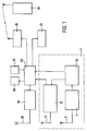
- FIG. 1 shows a receiving device in a vehicle that is a participant in a fleet
- FIG. 2 shows the control and disposition of the fleet via a trunked radio network and a long-wave transmitter
- FIG. 3 time slots for the transmission of additional data
- FIG. 4 an RDS channel in the VHF frequency band.
- 1 denotes a receiving device.
- the receiving device 1 contains a receiver 70 for GPS location data, which are fed to the receiver 70 via a first receiving antenna 71.
- the receiving device 1 also contains a second receiving antenna 6, which is connected to an evaluation unit 55 via a receiver 5 for DGPS correction location data.
- the DGPS correction location data evaluated by the evaluation unit 55 are fed to the receiver 70 for GPS location data.
- the evaluation unit 55 and the receiver 70 for GPS location data are connected to an on-board computer 60.
- a display device 20, a keyboard 25, a transceiver 65, a transponder 35 and a control device 40 are connected to the on-board computer 60.
- the transceiver 65 is provided with a transceiver antenna 66. Information from the on-board computer 60 can be fed to a radio device 30 which is matched to the transmission frequency of the transponder 35.
- Additional data on long wave are received in receiver 5 for DGPS correction location data and forwarded to evaluation unit 55.
- the received long-wave signal is time-divisionally divided into four time slots 80, 81, 82 and 83 according to FIG. 3.
- One of the four time slots 80, 81, 82 and 83, for example the first time slot 80, is reserved for the transmission of the DGPS correction location data.
- the remaining three time slots 81, 82 and 83 can be used for further additional data.
- the three remaining time slots 81, 82 and 83 are permanently assigned to the additional additional data or as required, that is to say that the additional services provided with the additional additional data are each associated with a corresponding time slot of the remaining three time slots 81, 82 and 83 coupled.
- the peculiarity of the use of long-wave signals for the transmission of the DGPS correction location data and the additional data is the constant (24 hours a day) availability and the large spatial range (greater than 500 km radius). In this way, unlimited and nationwide coverage or accessibility within the reception area can be achieved with a single omnidirectional transmitter. Geographical expansions that exceed the coverage performance by a single transmitter can be realized with several radio cells. On the other hand, due to the low signal bandwidth of the transmitter, undisturbed reception is possible even under very unfavorable reception conditions.
- the reception interference immunity and data integrity of the DGPS correction location data and the radio telegrams containing further additional data are ensured by using sufficiently known error-correcting block methods.
- the evaluation unit 55 has the task of selecting the incoming time slots 80, 81, 82 and 83. In this case, the DGPS correction location data present in the RTCM format in the first time slot 80 are selected and forwarded to the receiver 70 for GPS location data. The evaluation unit 55 also has the task of selecting from the remaining three remaining time slots 81, 82 and 83 the desired additional data or those required by the on-board computer 60 and forwarding them to the on-board computer 60.
- the GPS location data receiver 70 receives GPS signals emitted from satellites. In the receiver 70 for GPS location data, the corresponding satellite useful signals are evaluated to determine one's own location on the earth's surface. Other system solutions use on-board sensors for dead reckoning, but usually still have a GPS receiver as fallback level.
- the GPS location accuracy is hardly better than 100 m on average, this inaccuracy is reduced with the help of the DGPS correction location data to such an extent that the average location error is less than 5 m.
- the DGPS correction location data are acquired by means of suitable methods at a reference location and, as already described, are emitted via the first time slot 80 of a long-wave signal. With the aid of the DGPS correction location data supplied to the receiver 70 for GPS location data, the corrected position in the receiver 70 for GPS location data is then output in real time to the on-board computer 60 for storage.
- the on-board computer 60 has the task of forwarding the corrected location data to the transceiver 65 so that they can be transmitted to a control center via the transceiver antenna 66. Furthermore, the on-board computer 60 serves to evaluate the selected additional data supplied to it by the evaluation unit 55 and, if necessary, to display them via the display device 20.
- FIG. 2 shows the use of the arrangement according to FIG. 1 in a motor vehicle which is a participant in a fleet which is dispatched and controlled by a control center 90 via trunked radio in a range 10 according to FIG.
- 45 furthermore characterizes a first motor vehicle located in the spreading area 10 and 50 a second motor vehicle located outside the spreading area 10.
- Both motor vehicles 45 and 50 are equipped with a device according to FIG. 1.
- the two receiving antennas 71 and 6 are combined to form a common multi-band antenna 110.
- Measurement signals for the satellite-based positioning system GPS are transmitted via three satellites 75, 76 and 77 located in an orbit 78.
- a GPS reference receiver 85 is connected via a control center 90 to a long-wave transmitter 15, which transmits 16 DGPS correction location data via an omnidirectional antenna emits.
- the control center 90 is also connected via a trunked radio transceiver 115 to a first antenna 17 for trunked radio, which is located in the propagation area 10.
- the first antenna 17 for trunked radio together with a second and a third antenna 18 and 19 for trunked radio, provides the propagation area 10 with signals from the control center 90 second antenna 17 and 18 for trunked radio a data exchange with the control center 90 through.
- the multiband antennas 110 of the first and second motor vehicles 45 and 50 are supplied with measurement signals from the three satellites 75, 76 and 77, just like the GPS reference receiver 85 via its antenna 86.
- the range of the long-wave transmitter 15 with the omnidirectional antenna 16 is shown in FIG Concentric circles are shown, the center of which is the omnidirectional antenna 16. Both the first motor vehicle 45 in the range 10 and the second motor vehicle 50 outside the range 10 are within the range of the long-wave transmitter 15. The entire range 10 is within the range of the long-wave transmitter 15.
- the GPS reference receiver 85 receives GPS signals from the satellites 75, 76 and 77.
- the receiver-internal software calculates DGPS correction location data from the received measurement signals, which data are output to the control center 90 in RTCM format.
- the DGPS correction location data are stored in a computer in the control center 90 and are forwarded in real time to the long-wave transmitter 15.
- the DGPS correction location data is modulated in the long-wave transmitter 15 of a carrier wave and emitted via the omnidirectional antenna 16 in the first time slot 80 of the long-wave signal generated.
- the two motor vehicles 45 and 50 are participants in a fleet that is dispatched and controlled by the control center 90.
- the Control center 90 via the trunked radio transceiver 115 and the antennas 17, 18 and 19 for trunked radio control signals which can be received in the propagation area 10.
- the control information received in the corresponding motor vehicle via the transceiver antenna 66 is evaluated in the on-board computer 60 and displayed in the display device 20.
- the positions of the corresponding motor vehicle determined in the receiving device 1 are fed to the transceiver 65 via the on-board computer 60 and are emitted by the transceiver antenna 66.
- the radiated position data are fed to the trunked radio transceiver 115 via the antennas 17, 18 and 19 for trunked radio and from there to the control center 90 for evaluation.
- the control center 90 is informed of where the corresponding motor vehicles are located, so that they can be appropriately dispatched from there.
- the control information received in the corresponding motor vehicle is confirmed by corresponding keyboard input using the keyboard 25, which is forwarded via the on-board computer 60 to the transceiver 65 for transmission via the transceiver antenna 66.
- the first motor vehicle 45 in the expansion area 10 can be controlled by the control center 90.
- a participant of the fleet is outside the range 10, like the second motor vehicle 50, he can no longer be reached from the control center 90 via trunked radio.
- the second motor vehicle 50 can therefore only be reached via the long-wave transmitter 15, since it is within the range of this transmitter.
- the control center 90 no longer receives position data from the second vehicle 50, then it assumes that the second motor vehicle 50 has left the expansion area 10.
- the control center 90 is then one of the three remaining time slots 81, 82 and 83 of the long-wave signal generated in the long-wave transmitter 15 additional data, such as an encoded call that only that to address addressed second motor vehicle 50.
- This message is received by the multi-band antenna 110, selected in the evaluation unit 55, evaluated in the on-board computer 66 and displayed in the display device 20.
- the message contains, for example, a confirmation request telegram, which causes the fleet participants to either return to the area 10 or to contact the control center 90 by another route, such as a telephone or radio telephone. If there is no response from the fleet participant after a predetermined time, a signal is emitted via the transponder 35, which can be received by the radio 30 within the range of the transponder 35, so that a vehicle driver who has left the vehicle and is within the range of the Transponders 35 is located, can be reached. In this way, it is of course also possible to reach a vehicle driver who has left his vehicle within the range 10. However, the transponder 35 has a comparatively short range.
- a radio-controlled theft or immobilizer can also be implemented within the range of the long-wave transmitter 15.
- the corresponding additional data which are selected in the evaluation unit 55 and evaluated by the on-board computer 60, enter the control unit 40 and lead there to switching operations which activate or deactivate the immobilizer. If a vehicle driver leaves his motor vehicle, he notifies the control center 90, which then has additional data sent to activate the immobilizer. If the driver wants to use his motor vehicle again, he also informs the control center 90, which then sends out additional data for deactivating the immobilizer.
- control center 90 can also send out additional data in the remaining three time slots 81, 82 and 83, which contain a wake-up telegram which, after selection in the evaluation unit 55 and evaluation in the on-board computer 60 Representation of a switch-on request to switch on the transceiver 65 for communication with the control center 90 on the display device.
- the control center can have additional data sent out via the remaining three time slots 81, 82 and 83, which contain a sleep telegram, which, after selection in the evaluation unit 55 and evaluation in the on-board computer 60 Representation of a switch-off request to switch off the transceiver 65 or to switch on a power saving mode on the display device 20.
- the transponder 35 is only required if the radio 30 does not operate in the same frequency band as the transceiver 65, since a frequency conversion is then required. When using the same frequency band, no transponder 35 is required and it is sufficient to keep a channel free in this frequency band on which the radio 30 can be addressed.
- an ultra-short wave transmitter is used instead of the long wave transmitter 15.
- the receiver 5 for DGPS correction location data must also be an ultra-short wave receiver.
- 95 denotes an FM frequency band in which an audio signal and an RDS channel are transmitted.
- 4 101 identifies the spectrum of the audio signal in the lower part of the FM frequency band 95 and separately therefrom in the upper part of the FM frequency band is the lower sideband 105 and the upper sideband 106 of the RDS channel, which is modulated onto a subcarrier 100 located at the frequency f H in the middle between the two sidebands 105 and 106.
- the RDS channel 105, 106 is specially set up for additional data. Like the long-wave signal according to FIG. 3, the RDS channel 105, 106 can be divided into time slots 80, 81, 82 and 83 for the transmission of the DGPS correction location data and further additional data. The use of a dedicated RDS channel is also conceivable for long waves.
Landscapes
- Engineering & Computer Science (AREA)
- Radar, Positioning & Navigation (AREA)
- Remote Sensing (AREA)
- Physics & Mathematics (AREA)
- General Physics & Mathematics (AREA)
- Computer Networks & Wireless Communication (AREA)
- Position Fixing By Use Of Radio Waves (AREA)
Applications Claiming Priority (2)
| Application Number | Priority Date | Filing Date | Title |
|---|---|---|---|
| DE19538694 | 1995-10-18 | ||
| DE19538694A DE19538694A1 (de) | 1995-10-19 | 1995-10-19 | Empfangseinrichtung zur Auswertung von Ortungsdaten |
Publications (2)
| Publication Number | Publication Date |
|---|---|
| EP0769704A2 true EP0769704A2 (fr) | 1997-04-23 |
| EP0769704A3 EP0769704A3 (fr) | 1998-11-25 |
Family
ID=7775106
Family Applications (1)
| Application Number | Title | Priority Date | Filing Date |
|---|---|---|---|
| EP96116131A Ceased EP0769704A3 (fr) | 1995-10-18 | 1996-10-09 | Dispositif de réception pour l'évaluation de données de localisation |
Country Status (2)
| Country | Link |
|---|---|
| EP (1) | EP0769704A3 (fr) |
| DE (1) | DE19538694A1 (fr) |
Cited By (3)
| Publication number | Priority date | Publication date | Assignee | Title |
|---|---|---|---|---|
| EP0982601A1 (fr) * | 1998-08-14 | 2000-03-01 | Robert Bosch Gmbh | Procédé et récepteur de données pour recevoir des signaux radio contenant des données de correction pour GPS |
| CN1087243C (zh) * | 1997-10-07 | 2002-07-10 | 财团法人工业技术研究院 | 应用调频副载波无线电数据系统及差分全球定位系统的汽车防盗系统 |
| EP0926020A3 (fr) * | 1997-12-22 | 2002-09-18 | Delphi Technologies, Inc. | Commande d'un véhicule par utilisation de messagerie avec f.m. et des sous-porteuses |
Families Citing this family (9)
| Publication number | Priority date | Publication date | Assignee | Title |
|---|---|---|---|---|
| DE19725669C1 (de) | 1997-06-18 | 1998-10-22 | Daimler Benz Ag | Verfahren zur Stilllegung eines Fahrzeugs |
| DE19733507A1 (de) * | 1997-08-04 | 1999-03-04 | Peter Rabels | Verfahren zur Verwendung eines Mobilfunktelefones und SMS-Vorrichtung für Fahr- und Flugplaninformation und Bahn- und Flugbuchung |
| KR20010023816A (ko) | 1997-09-09 | 2001-03-26 | 칼 하인쯔 호르닝어 | 이동 무선전화 단말기들, 무선국 및 이동 무선전화단말기에 의해 방출되는 전자기 방사선으로부터 제한된국부 영역을 보호하는 방법 |
| DE19802595A1 (de) * | 1998-01-23 | 1999-07-29 | Volkswagen Ag | Kraftfahrzeug mit einem Navigationssystem |
| DE10038539A1 (de) * | 2000-08-03 | 2002-02-21 | Bosch Gmbh Robert | Verfahren und Vorrichtung zur energiesparenden Dichtheitsprüfung einer Brennstofftankanlage insbesondere eines Kraftfahrzeuges |
| DE10119886A1 (de) * | 2001-04-24 | 2002-10-31 | Mueller Umwelttechnik | Einrichtung und Verfahren zum Erfassen von Positionsdaten |
| DE10121260A1 (de) * | 2001-04-30 | 2002-11-21 | Siemens Ag | Navigationssystem als Erweiterung bei satellitenunterstützten Navigationsgeräten im "Indoor-Bereich" |
| TWI269046B (en) * | 2004-06-29 | 2006-12-21 | Lite On Automotive Corp | A GPS having a vehicle condition real-time reporting function |
| TWI246973B (en) * | 2004-06-30 | 2006-01-11 | Sin Etke Technology Co Ltd | Vehicle anti-thief system by making the vehicle unable to operate normally |
Family Cites Families (29)
| Publication number | Priority date | Publication date | Assignee | Title |
|---|---|---|---|---|
| US4161730A (en) * | 1977-10-17 | 1979-07-17 | General Electric Company | Radio determination using satellites transmitting timing signals with correction by active range measurement |
| GB1595146A (en) * | 1977-10-17 | 1981-08-05 | Gen Electric | Position surveillance using one active ranging satellite and time of arrival of a signal from an independent satellite |
| US4651156A (en) * | 1982-02-08 | 1987-03-17 | Mcgraw-Edison Co. | Integrated radio location and communication system |
| US4751512A (en) * | 1986-01-21 | 1988-06-14 | Oceanonics, Inc. | Differential navigation system for remote mobile users |
| DE3805810A1 (de) * | 1988-02-24 | 1989-09-07 | Amend Volker | Kommunikationssystem fuer fahrzeuge |
| US5025253A (en) * | 1988-10-14 | 1991-06-18 | Secura Corporation | System and method for remotely monitoring the connect/disconnect status of a multiple part vehicle |
| US4897642A (en) * | 1988-10-14 | 1990-01-30 | Secura Corporation | Vehicle status monitor and management system employing satellite communication |
| US5003317A (en) * | 1989-07-11 | 1991-03-26 | Mets, Inc. | Stolen vehicle recovery system |
| JPH0827593B2 (ja) * | 1989-10-24 | 1996-03-21 | マツダ株式会社 | 移動体用ナビゲーション装置 |
| JPH082029B2 (ja) * | 1989-10-27 | 1996-01-10 | 日産自動車株式会社 | 車載用gps受信機 |
| JP3017772B2 (ja) * | 1990-06-06 | 2000-03-13 | マツダ株式会社 | 車両用ナビゲーション装置 |
| FR2670002B1 (fr) * | 1990-11-30 | 1994-06-24 | Leroy Philippe | Procede et systeme pour determiner la position de mobiles depuis une station de localisation et appareillage pour la mise en óoeuvre du procede. |
| DE4136136C1 (fr) * | 1991-11-02 | 1993-03-04 | Westdeutscher Rundfunk, Anstalt Des Oeffentlichen Rechts, 5000 Koeln, De | |
| US5311194A (en) * | 1992-09-15 | 1994-05-10 | Navsys Corporation | GPS precision approach and landing system for aircraft |
| US5361212A (en) * | 1992-11-02 | 1994-11-01 | Honeywell Inc. | Differential GPS landing assistance system |
| MY110677A (en) * | 1992-12-02 | 1999-01-30 | Voxson Pty Ltd | Improvements in positioning systems |
| US5422813A (en) * | 1992-12-17 | 1995-06-06 | Stanford Telecommunications, Inc. | No-outage GPS/commercial RF positioning system |
| US5477228A (en) * | 1993-04-13 | 1995-12-19 | Differential Corrections Inc. | Differential global positioning system using radio data system |
| AU7067394A (en) * | 1993-06-21 | 1995-01-17 | Elke Van Buren | System for summoning help for vehicle occupants or other people carrying a mobile telephone |
| GB2279478A (en) * | 1993-06-26 | 1995-01-04 | Ian Paul Downing Hunter | Vehicle security |
| DE4322288A1 (de) * | 1993-07-05 | 1995-01-12 | Amazonen Werke Dreyer H | Verfahren zur Auswertung von Verkehrsmeldungen |
| DE4326237C1 (de) * | 1993-07-31 | 1994-12-15 | Gsp Sprachtechnologie Ges Fuer | Verfahren zur Standortbestimmung von Fahrzeugen des öffentlichen Personenverkehrs |
| DE4340138A1 (de) * | 1993-11-25 | 1995-06-01 | Klaus Stanzl | Ortungssystem für Kraftfahrzeuge |
| DE4403873A1 (de) * | 1994-02-08 | 1994-09-08 | Wenner Manfred E | Schutz von beweglichen Gegenständen vor Entwendung und Wiederauffindung von beweglichen Gegenständen bei Verlust |
| DE4403990C2 (de) * | 1994-02-09 | 1996-09-05 | Panasonic Deutschland Gmbh | Verfahren zur Diebstahlsicherung und zum Auffinden von gestohlenen mobilen Audiogeräten und Kraftfahrzeugen und Vorrichtung zur Durchführung des Verfahrens |
| DE4405385A1 (de) * | 1994-02-19 | 1995-09-07 | Bernd Dipl Ing Eslinger | Elektronische Vorrichtung zur Verhinderung der unbefugten Inbetriebnahme von Kraftfahrzeugen |
| GB2287149B (en) * | 1994-03-02 | 1998-02-25 | Cossor Electronics Ltd | Differential global positioning system |
| DE9406605U1 (de) * | 1994-04-20 | 1994-09-22 | VHB-Funktechnik GmbH, 34132 Kassel | System zur Ortung von gestohlenen Fahrzeugen |
| DE4429121C1 (de) * | 1994-08-17 | 1996-02-22 | Siemens Ag | Navigationssystem für ein Fahrzeug |
-
1995
- 1995-10-19 DE DE19538694A patent/DE19538694A1/de not_active Withdrawn
-
1996
- 1996-10-09 EP EP96116131A patent/EP0769704A3/fr not_active Ceased
Cited By (4)
| Publication number | Priority date | Publication date | Assignee | Title |
|---|---|---|---|---|
| CN1087243C (zh) * | 1997-10-07 | 2002-07-10 | 财团法人工业技术研究院 | 应用调频副载波无线电数据系统及差分全球定位系统的汽车防盗系统 |
| EP0926020A3 (fr) * | 1997-12-22 | 2002-09-18 | Delphi Technologies, Inc. | Commande d'un véhicule par utilisation de messagerie avec f.m. et des sous-porteuses |
| EP0982601A1 (fr) * | 1998-08-14 | 2000-03-01 | Robert Bosch Gmbh | Procédé et récepteur de données pour recevoir des signaux radio contenant des données de correction pour GPS |
| US6332070B1 (en) | 1998-08-14 | 2001-12-18 | Robert Bosch Gmbh | Method and data receiver device for reception of a radio signal containing correction data for a global navigation satellite system |
Also Published As
| Publication number | Publication date |
|---|---|
| DE19538694A1 (de) | 1997-04-24 |
| EP0769704A3 (fr) | 1998-11-25 |
Similar Documents
| Publication | Publication Date | Title |
|---|---|---|
| DE69021900T2 (de) | Mobiles Navigationssystem. | |
| DE69227269T2 (de) | Gegenstandsortungssystem | |
| DE69029950T2 (de) | Auf satellit basierendes globales rufsystem | |
| DE69032430T2 (de) | Satellit basiertes gleichwellen-rufsystem | |
| DE69837034T2 (de) | Satelliten rundfunksystem | |
| DE69128518T2 (de) | Verbesserter Zellular-Telefondienst mit Spreizspektrumübertragung | |
| DE69608464T2 (de) | Verfahren zur verbesserung der effizienz der verwendung eines funkkanals in überlappenden bedeckungszonen | |
| DE69032909T2 (de) | Globales satellitenkommunikationssystem mit geographischer protokollumsetzung | |
| DE69810706T2 (de) | Informationssystem für Nutzer eines öffentlichen Nahverkehrsnetzes, das über die voraussichtlichen Wartezeiten an den Haltestellen informiert | |
| DE4424412A1 (de) | Funktelekommunikationssystem mit Satelliten-Navigation | |
| DE60028017T2 (de) | Gerät und verfahren für funkruf in einer satelliten kommunikationsanordnung mit ortsbestimmung des benutzers | |
| EP0814345A2 (fr) | Système de positionnement d'objet mobile, en particulier pour véhicules | |
| DE69218023T2 (de) | Zellulares Telefonsatellitensystem | |
| DE69331710T2 (de) | Positionierungssystem unter verwendung eines mobiltelefons zur übertragung von korrektursignalen | |
| EP0769704A2 (fr) | Dispositif de réception pour l'évaluation de données de localisation | |
| EP0915577B1 (fr) | Système pour l'utilisation de terminaux mobiles dans un avion de ligne | |
| DE60023310T2 (de) | Verfahren zu weitreichendem funkruf | |
| WO1993009446A1 (fr) | Systeme de determination de la position d'objets mobiles | |
| DE19836966A1 (de) | Verfahren und Datenempfänger zum Empfang von Korrekturdaten enthaltenden Funksignalen für ein Global Navigation Satellite System | |
| DE60225394T2 (de) | Verfahren und Sytem zur geographischen Ortung in Kommunikations- Netzwerken und Terminal dafür | |
| DE69519523T2 (de) | Übertragungsanordnung mit satelliten niedriger höhe und optimaler erdbeleuchtung für ein telekommunikationsnetz mit speicherung und durchschaltung | |
| EP0932992B1 (fr) | Procede de transmission de signaux radioelectriques | |
| DE69033216T2 (de) | Weltweites kommunikationssystem, empfänger und arbeitsmethode dafür | |
| DE10011702A1 (de) | Verfahren zur standortbezogenen Information von Verkehrsteilnehmern | |
| DE102005039807B4 (de) | Bereitstellung von Informationen in Satellitennavigationssystemen |
Legal Events
| Date | Code | Title | Description |
|---|---|---|---|
| PUAI | Public reference made under article 153(3) epc to a published international application that has entered the european phase |
Free format text: ORIGINAL CODE: 0009012 |
|
| AK | Designated contracting states |
Kind code of ref document: A2 Designated state(s): CH DE ES FR GB IT LI SE |
|
| PUAL | Search report despatched |
Free format text: ORIGINAL CODE: 0009013 |
|
| AK | Designated contracting states |
Kind code of ref document: A3 Designated state(s): CH DE ES FR GB IT LI SE |
|
| 17P | Request for examination filed |
Effective date: 19990525 |
|
| 17Q | First examination report despatched |
Effective date: 20020709 |
|
| STAA | Information on the status of an ep patent application or granted ep patent |
Free format text: STATUS: THE APPLICATION HAS BEEN REFUSED |
|
| 18R | Application refused |
Effective date: 20030404 |