EP0769708A1 - Procédés et dispositifs de mesure de caractéristiques d'une formation traversée par un trou de forage - Google Patents
Procédés et dispositifs de mesure de caractéristiques d'une formation traversée par un trou de forage Download PDFInfo
- Publication number
- EP0769708A1 EP0769708A1 EP96402206A EP96402206A EP0769708A1 EP 0769708 A1 EP0769708 A1 EP 0769708A1 EP 96402206 A EP96402206 A EP 96402206A EP 96402206 A EP96402206 A EP 96402206A EP 0769708 A1 EP0769708 A1 EP 0769708A1
- Authority
- EP
- European Patent Office
- Prior art keywords
- current
- annular
- electrodes
- sonde
- electrode
- Prior art date
- Legal status (The legal status is an assumption and is not a legal conclusion. Google has not performed a legal analysis and makes no representation as to the accuracy of the status listed.)
- Granted
Links
Images





Classifications
-
- G—PHYSICS
- G01—MEASURING; TESTING
- G01V—GEOPHYSICS; GRAVITATIONAL MEASUREMENTS; DETECTING MASSES OR OBJECTS; TAGS
- G01V3/00—Electric or magnetic prospecting or detecting; Measuring magnetic field characteristics of the earth, e.g. declination, deviation
- G01V3/18—Electric or magnetic prospecting or detecting; Measuring magnetic field characteristics of the earth, e.g. declination, deviation specially adapted for well-logging
- G01V3/20—Electric or magnetic prospecting or detecting; Measuring magnetic field characteristics of the earth, e.g. declination, deviation specially adapted for well-logging operating with propagation of electric current
Definitions
- the present invention relates to the field of measurement tools, e.g. suitable for being used in equipment for oil prospecting and production.
- this type of activity requires sondes or sensors, in particular electrical or electromagnetic sondes or sensors to be inserted therein to perform measurements enabling, inter alia , the fluids present in the ground and layers around the borehole to be characterized, and also enabling the dip of the layers to be characterized.
- the term "logging" is used to designate any continuos recording as a function of depth of variations in a given characteristic of the formations around a borehole.
- An important characteristic to discover in a borehole is the resistivity of the surrounding ground formation, whether the resistivity is measured omnidirectionally or in azimuth, i.e. in various directions perpendicular to the axis of the borehole.
- resistivity is fundamental in computing saturation, and resistivity may be measured in various different ways. However whatever tool is used, measurement is always based on the same principle:
- Known tools enabling the resistivity of the surrounding formations to be measured include tools of the "laterolog" type.
- Document EP-544 583 also describes such a tool and a direct focusing technique. That document describes both a "deep” (LLd) investigation mode and a “shallow” (LLs) investigation mode. Measurements are produced, in particular measurement of the resistivity and the azimuth resistivity of the surrounding formation.
- the tools described in those two documents require the investigation currents that are emitted from the annular current electrode(s) into the ground formation to be focused directly. Means must therefore be implemented for performing such focusing.
- that requires a feedback loop for adjusting the focusing current(s) as a function, for example, of a signal representative of a focusing potential.
- the gain must be limited in order to ensure stability.
- the electrodes are not exactly at the same potential because of the finite gain, and that introduces error into the measurement. Even though the error is very small, particularly with standard tools of the "double laterolog" type, it can become large when the spacing between the focusing voltage measurement electrodes is small in order to improve the resolution of the apparatus.
- the invention provides methods and apparatuses, e.g. for measuring formation characteristics, that avoid making use of direct focusing.
- the techniques described are compatible with electrode arrangements that already exist on certain sondes.
- the invention provides a method of measuring the characteristics of formations around a borehole, the method comprising:
- This method does not require focusing to be performed directly, and it makes use solely of focusing by computation. Since the simulation is generally performed by computing devices on the surface, the measurement tool itself is considerably simplified. In addition, insofar as no focusing is performed directly while measurements are being made, there is no need for focusing current control and/or regulation means. This avoids all of the focusing current feedback loops.
- This first method thus performs "deep” computed focusing (LLd).
- the invention also provides a method of measuring the characteristics of formations around a borehole, the method comprising:
- this method makes it possible to avoid performing focusing directly, replacing direct focusing with computed focusing.
- this second method is compatible with electrode structures that are to be found on known sondes. Also, both methods are mutually compatible: they can be implemented using the same electrode structure on the same sonde.
- the second method makes it possible to perform "shallow" computed focusing (LLs).
- each of the methods can be followed by a step during which signals are produced that are representative of one or more characteristics of the surrounding media (omnidirectional resistivity or azimuth resistivity).
- a weighting coefficient is deduced for a linear combination of the two real or "effective" operating modes of the sonde, so as to obtain a computed mode for which the resulting focusing voltage is zero.
- the invention also relates to apparatus for implementing the first above-described method.
- the invention also provides apparatus for measuring the characteristics of formations around a borehole, the apparatus comprising:
- the above apparatus serves to implement the first above-described method with all of the advantages associated therewith.
- This apparatus serves to implement the second above-described method.
- This apparatus comprises:
- This second apparatus is compatible with the first in the sense that a single tool can be used for both of them.
- the means for implementing computed focusing which are essentially computer means, can also be common.
- the user has equipment that can be used, at will, for deep computed focusing (LLd) and/or for shallow computed focusing (LLs).
- Both apparatuses implement a second effective mode of operation which is identical, thereby reinforcing their compatibility still further.
- means may be provided for producing signals representative of one or more characteristics of the surrounding media, e.g. the omnidirectional resistivity or the azimuth resistivity of the formation.
- the sonde may include:
- the second variant makes it possible to perform high resolution measurements. It is then also possible to perform simultaneously high resolution measurements and standard resolution measurements.
- the invention also provides apparatus for measuring the characteristics of formations around a borehole, the apparatus comprising:
- FIG. 1 Overall implementation of the invention is initially shown diagrammatically in Figure 1 where there can be seen logging apparatus enabling the characteristics of terrestrial formations 11 surrounding a well or borehole 10 to be determined.
- the apparatus comprises a sonde 12 which is suspended down the borehole at the end of a multiconductor cable 13.
- the cable 13 passes over a sheave 14 and is wound on a drum 15 which serves to move the sonde 12 along the borehole.
- the drum 15 forms part of a surface unit 16 which may also include means for computer processing data measured by the sonde while it is being displaced in the borehole.
- the sonde 12 is elongate in shape. It comprises a body 17 having a top portion 20 made of a metal case enclosing electrical circuits, and a bottom portion 21 including an array 22 of electrodes making it possible, in particular, to determine the resistivity of surrounding formations or of drilling mud.
- the sonde may be used in combination with apparatus as described in document FR-2 710 987.
- This figure is a diagrammatic representation of the array of electrodes on its own, i.e. without the body of the sonde.
- the array of electrodes comprises firstly a pair A 0 , A 0 ' of annular current electrodes. Between these current electrodes there is disposed an array of azimuth electrodes A azi . There are N such electrodes distributed around a circumference of the body 17 of the sonde.
- Potential measuring electrodes M 1 , M' 1 , M 2 , M' 2 and A 0 *, A 0 *, are provided.
- the electrodes A 0 * and A 0 *' subdivide each current electrode into two portions; thus, a portion of current electrode A 0 is situated above the potential measuring electrodes A 0 *, and a portion of A 0 is situated beneath a A 0 *, and the same applies for A 0 ' and A 0 *'.
- This disposition makes it possible to perform measurements that are more accurate when variations in contact impedance occur at the surfaces of the current electrodes.
- first and second guard electrodes A 1 and A 2 being situated in the top portion of the set of electrodes, while third and fourth guard electrodes A' 1 and A' 2 are situated in the bottom portion of the set of electrodes. Electrodes A 1 * and A 1 *' are also provided to measure potential in the mud column close to the electrodes A 1 and A' 1 .
- Figure 2 also shows, in diagrammatic manner, the relative disposition of the set of electrodes, of the borehole 10 (including drilling mud 24), and of the formations 11.
- Current lines I 0,c , I' 0,c and focusing currents I 1,c and I' 1,c as obtained by deep computed focusing are also shown. These currents are not effectively used, but they are deduced from effective operating modes described below with reference to Figures 3A to 3C and 4A to 4C.
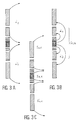
- a first effective operating mode ( Figure 3A) currents i 1 and i' 1 of great penetration depth into the surrounding formations are emitted from the guard electrodes. At infinity, these currents return to the surface.
- the second effective operating mode ( Figure 3B) emits current with low penetration depth into the surrounding formations.
- the total current I t,2 emitted into the formation is zero.
- Figure 3C shows the investigation current I 0,c and the focusing currents I 1,c and I' 1,c obtained using computed focusing, e.g. implementing one of the techniques described below.
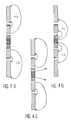
- guard currents i 2 , i' 2 appear going from the guard electrodes A 1 and A' 1 towards the electrodes A 2 and A' 2 : these currents have a penetration depth that is intermediate between the effective operating mode described above with reference to Figure 3B and the effective operating mode described above with reference to Figure 3A. That is why the penetration depth of these currents is called "medium".
- the effective operating mode of Figure 4B is identical to the effective operating mode as described above with reference to Figure 3B.
- Figure 4C shows the currents obtained in computed mode using a technique that is explained below.
- the difference between the current structures of Figures 3C and 4C shows that in the first case ( Figure 3C) focusing is performed over a large depth (deep computed focusing LLd), whereas in the second case focusing takes place only over a shallower depth (shallow computed focusing, LLs).
- a sonde or apparatus for implementing the invention may be designed to operate in all three above-described modes.
- the various modes may be implemented simultaneously, at different frequencies.
- the mode using current emission with great penetration depth (Figure 3A) may be implemented at 35 Hz
- the mode having current emitted with shallow penetration depth ( Figures 3B, 4B) is implemented at 162 Hz
- the mode with current being emitted at medium penetration depth (Figure 4A) is implemented at 288 Hz. If the frequencies chosen are equal or similar, then the effective operating modes are preferably implemented in succession.
- a signal or signals representative of the resistivity of the formation may be deduced by simulation after computing the focused mode.
- an operating mode is fully described by the data from the investigation current(s), the total current emitted into the formation, a focusing voltage, a sonde voltage, and a voltage difference between two adjacent guard electrodes.
- the investigation current is written I 0
- the sonde voltage is written ⁇ V s
- the focusing voltage is written ⁇ V f .
- K is a coefficient which depends on the geometry of the sonde.
- the data obtained on the voltages and the currents of the effective modes may, for example, be measured and then stored in data storage means.
- the coefficient ⁇ is computed and the resistivity is obtained subsequently, e.g. using a known type of computer specially programmed for implementing this type of computation.
- the computer may be contained in the surface unit 16 (see Figure 1), for example.
- A is a 2 x 3 matrix whose coefficients are written as follows:
- the proportionality factor is different for the two computed focused modes, i.e. deep mode (LLd) and shallow mode (LLs).
- This second computation technique requires measured values of currents and of voltages for the effective modes to be stored, and it implements a subsequent step of computing transfer impedances.
- the computation may be performed by a computer of known type programmed appropriately for implementing this type of computation.
- the sonde When the sonde includes an array of azimuth electrodes, as in the structures described above with reference to Figures 2 and 5, it is also possible to implement measurement of azimuth resistivity of the formation. Thus, a measurement is obtained of the resistivity of the formation in a particular direction about the sonde as defined by one of the azimuth electrodes. The result may be obtained for a computed focusing mode that is deep (LLd) or shallow (LLs).
- the investigation currents which flow in the formation generate a voltage in the mud column, and this voltage is measured between the azimuth electrodes and the reference electrodes A 0 * and A 0 *'.
- ⁇ V azi,j value of ⁇ V azi in focused mode
- ⁇ V azi,c ⁇ V azi,2 - ⁇ V f,2 ⁇ V f,1 ⁇ V azi,1
- c designates one or other of the computed focused modes, deep (LLd) or shallow (LLs).
- the measurements performed with an electrode structure such as that described above with reference to Figures 2 or 5 are high resolution measurements: this is due to the presence in the center of the sonde, i.e. between the two annular current electrodes A 0 and A' 0 , of an array of voltage measuring electrodes. Under such conditions, the width of a computed investigation current is narrower than when two pairs of annular voltage measuring electrodes are disposed on either side of the current electrodes.
- Figures 6A and 6B show how the correction factor for the hole effect or the ratio R cor /R a (where R cor is the true resistivity of the formation and where R a is the measured resistivity of the medium, before correction) varies as a function of the ratio R a /R m (or contrast, where R m is the resistivity of the mud), for deep computed focusing, respectively at standard resolution and at high resolution.
- the curves I-VI (I'-VI') are given for hole diameter increasing in steps of 5 cm from 15 cm to 40 cm.
- Figures 7A and 7B show variation in the same parameter for shallow computed focusing, at standard resolution ( Figure 7A) and at high resolution ( Figure 7B).
- Figure 8 shows an example of a log obtained using an apparatus of the prior art at standard resolution (curve A) and using apparatus of the invention at high resolution (curve B). Finer structures are clearly visible in curve B.
- the electrode arrangement of Figure 9 has two guard electrodes A, A' each of which comprises a single piece: this structure makes it possible to implement the effective operating modes described above with reference to Figures 3A and 3B, but not the effective mode of Figure 4A.
- the electrode arrangement of Figure 10 comprises, on either side of the above-described central assembly, two pairs of annular guard electrodes A 1 , A' 1 and A 2 , A' 2 .
- Annular electrodes A 1 * and A 1 *' make it possible to measure potentials in the mud column close to the annular electrodes A 1 and A' 1 .
- this electrode structure makes it possible to implement the effective operating modes described above with reference to figures 3A, 3B, 4A, and 4B.
- the focusing voltage may be given by the difference V 2 -V 1
- the sonde voltage is given by the difference V 1 -V r
- V r is the potential of a remote reference, e.g. on the cable 13.
- These two electrode arrangements include single-piece annular guard electrodes: they are suitable for implementing only the effective operating modes of Figures 3A and 3B.
- these one-piece annular electrodes can be replaced by structures of guard electrodes at either end of the sonde similar to the structures of guard electrodes in Figure 10 (A 1 , A 2 , A' 1 , A' 2 ): such a structure would be suitable for implementing the effective operating modes of Figures 3A, 3B and 4A, 4B.
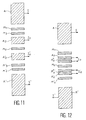
- annular voltage measuring electrode M 0 Because of the presence of an annular voltage measuring electrode M 0 between two current electrodes in the structures of Figures 11 and 12, they are capable of performing high resolution measurements, for the same reason as that explained above with respect to the electrode structure of Figure 5. It is possible simultaneously to perform high resolution measurement and standard resolution measurement.
- the focusing voltage is equal to V 1 -V 0 , where V 1 is the mean voltage of electrode pair M 1 , M' 1 , and V 0 is the voltage of electrode M 0 .
- the sonde voltage is equal to V 3 -V 1 for the structure of Figure 11 where V3 is the mean voltage of the pair M3, M' 3 and it is equal to V 1 -V r for the structure of Figure 12 where V r is the potential of a remote reference, e.g. on the cable 13.
- V r is the potential of a remote reference, e.g. on the cable 13.
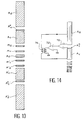
- FIG. 13 An electrical circuit for implementing a sonde suitable for performing the measurement method of the invention by computed focusing is shown in Figure 13.
- the electrode structure concerned is that described above with reference to Figure 9.
- a current source 80 e.g. situated at the surface sends a total current I t for operating the sonde in the first effective mode. This current is delivered via a cable 82.
- Means are provided (resistor 84, amplifier 86, phase measuring circuit 88) for measuring the phase of the current I t .
- the current I 0 (for operation in the second effective mode) is produced by a generator 90 controlled by a digital processor 92, a digital-to-analog converter 94 and a lowpass filter 96.
- the focusing voltage is obtained by taking a difference and amplifying, using differential amplifiers 98 and 100 which take the differences between the voltages from pairs of annular electrodes M 1 , M 2 and M' 1 , M' 2 .
- the signals from the differential amplifiers are applied to a summing circuit 104 whose output signal is filtered (bandpass filter 106) and is subsequently applied to a multiplier 108.
- the signals for measuring the sonde voltage are formed by differential amplifiers 110, 112 amplifying the voltage differences between each of the pair of electrodes M 1 , M' 1 and a remote reference voltage, e.g. taken from R on the cable.
- the resulting signals are fed to a summing circuit 114 whose output is then filtered (bandpass filter 116), and the filtered output signal is subsequently applied to the multiplier 108.
- the multiplexer is connected to an analog-to-digital converter 118 in turn connected to the digital processor 92.
- the signal is subsequently conveyed to a transmitter 120.
- the apparatus also includes a receiver 122 and a computer 124.
- FIG 14. An electrical circuit for monitoring equality of potential, e.g. between electrodes A 1 * and A 2 in Figure 2, is given in Figure 14.
- An electrode A 1 * is associated with electrode A 1 so as to perform potential measurement in the mud column close to A 1 . This makes it possible to avoid the effects of contact impedance on electrode A 1 .
- An amplifier 70 delivers a signal proportional to the voltage measured between the electrode A 2 and the electrode A 1 *.
- a differential amplifier 72 serves to compare the resulting signal with ground potential.
- the amplifier 72 delivers a non-zero signal to a transformer 74 which then controls a different distribution of currents between the electrodes A 1 and A 2 . It is thus possible to apply the signal V A1 *+V A1 *'-V A2 -V A2 ' to the input of amplifier 70.
- the electrodes A 1 and A' 1 and the electrodes A 2 and A' 2 are then short circuited. All of the elements 70 to 74 can be integrated in the body of the sonde lowered down the borehole.
Landscapes
- Life Sciences & Earth Sciences (AREA)
- Engineering & Computer Science (AREA)
- Environmental & Geological Engineering (AREA)
- Geology (AREA)
- Remote Sensing (AREA)
- Physics & Mathematics (AREA)
- General Life Sciences & Earth Sciences (AREA)
- General Physics & Mathematics (AREA)
- Geophysics (AREA)
- Geophysics And Detection Of Objects (AREA)
- Investigating Or Analyzing Materials By The Use Of Electric Means (AREA)
- Control Of Stepping Motors (AREA)
- Eye Examination Apparatus (AREA)
Applications Claiming Priority (2)
| Application Number | Priority Date | Filing Date | Title |
|---|---|---|---|
| FR9512348 | 1995-10-20 | ||
| FR9512348A FR2740169B1 (fr) | 1995-10-20 | 1995-10-20 | Procedes et dispositifs de mesure de caracteristiques d'une formation traversee par un trou de forage |
Publications (2)
| Publication Number | Publication Date |
|---|---|
| EP0769708A1 true EP0769708A1 (fr) | 1997-04-23 |
| EP0769708B1 EP0769708B1 (fr) | 2001-09-26 |
Family
ID=9483744
Family Applications (1)
| Application Number | Title | Priority Date | Filing Date |
|---|---|---|---|
| EP96402206A Expired - Lifetime EP0769708B1 (fr) | 1995-10-20 | 1996-10-16 | Procédés et dispositifs de mesure de caractéristiques d'une formation traversée par un trou de forage |
Country Status (8)
| Country | Link |
|---|---|
| US (1) | US5852363A (fr) |
| EP (1) | EP0769708B1 (fr) |
| AU (1) | AU717730B2 (fr) |
| CA (1) | CA2188207C (fr) |
| DE (1) | DE69615493T2 (fr) |
| DK (1) | DK0769708T3 (fr) |
| FR (1) | FR2740169B1 (fr) |
| NO (1) | NO310895B1 (fr) |
Cited By (2)
| Publication number | Priority date | Publication date | Assignee | Title |
|---|---|---|---|---|
| GB2322943A (en) * | 1997-03-07 | 1998-09-09 | Western Atlas Int Inc | Well logging |
| EP0941742A3 (fr) * | 1998-02-19 | 2000-03-22 | Arzneimittel GmbH Apotheker Vetter & Co. Ravensburg | Procédé pour le contrôle sans contact de la position prescrite du capuchon de protection de l'aiguille sur la canule d'une seringue médicale ainsi que l'appareil pour la mise en oeuvre de ce procédé |
Families Citing this family (12)
| Publication number | Priority date | Publication date | Assignee | Title |
|---|---|---|---|---|
| US7027967B1 (en) | 2000-06-02 | 2006-04-11 | Schlumberger Technology Corporation | Method and system for indicating anisotropic resistivity in an earth formation |
| US7042225B2 (en) * | 2003-12-12 | 2006-05-09 | Schlumberger Technology Corporation | Apparatus and methods for induction-SFL logging |
| US7098664B2 (en) * | 2003-12-22 | 2006-08-29 | Halliburton Energy Services, Inc. | Multi-mode oil base mud imager |
| CN100483153C (zh) * | 2006-03-24 | 2009-04-29 | 黄委会水科院高新工程技术研究开发中心 | 聚束直流电阻率探测方法 |
| US8030938B2 (en) * | 2008-03-26 | 2011-10-04 | Baker Hughes Incorporated | Apparatus and method for imaging subsurface materials using a pad having a plurality of electrode sets |
| US20100026305A1 (en) * | 2008-07-31 | 2010-02-04 | Baker Hughes Incorporated | Method and Apparatus for Imaging Boreholes |
| WO2013066436A1 (fr) * | 2011-11-02 | 2013-05-10 | Halliburton Energy Services, Inc. | Outils et procédés de diagraphie focalisée de résistivité à réseaux multiples au moyen d'électrodes de surveillance séparées |
| US9547100B2 (en) | 2010-11-15 | 2017-01-17 | Halliburton Energy Services, Inc. | Multi-array laterolog tools and methods with differential voltage measurements |
| US9081114B2 (en) | 2011-11-02 | 2015-07-14 | Halliburton Energy Services, Inc. | Multi-array laterolog tools and methods with split monitor electrodes |
| MX336173B (es) * | 2012-01-03 | 2016-01-06 | Halliburton Energy Services Inc | Herramienta laterolog de arreglo enfocado. |
| US9696451B2 (en) * | 2014-06-10 | 2017-07-04 | Halliburton Energy Services, Inc. | Resistivity logging tool with excitation current control based on multi-cycle comparison |
| US10001581B2 (en) * | 2014-06-10 | 2018-06-19 | Halliburton Energy Services, Inc. | Resistivity logging tool with excitation current control |
Citations (4)
| Publication number | Priority date | Publication date | Assignee | Title |
|---|---|---|---|---|
| FR2547064A1 (fr) * | 1983-05-31 | 1984-12-07 | Gearhart Ind Inc | Procede et appareil pour l'exploration de formations geologiques dans des trous de sonde |
| US4646026A (en) * | 1983-05-31 | 1987-02-24 | Gearhart Industries, Inc. | Method and apparatus for measuring resistivity of an earth formation |
| US4714889A (en) * | 1985-07-31 | 1987-12-22 | Chevron Research Company | Method of interpreting impedance distribution of an earth formation using precursor logging data provided by a multi-electrode logging array stationary within a borehole |
| EP0540425A2 (fr) * | 1991-10-31 | 1993-05-05 | Schlumberger Limited | Procédé et dispositif pour étudier les formations terestre |
Family Cites Families (3)
| Publication number | Priority date | Publication date | Assignee | Title |
|---|---|---|---|---|
| FR2666661B1 (fr) * | 1990-09-12 | 1993-03-26 | Schlumberger Services Petrol | Procede et dispositif de diagraphie pour mesurer la resistivite des formations geologiques. |
| FR2684453B1 (fr) * | 1991-11-28 | 1994-03-11 | Schlumberger Services Petroliers | Procede et dispositif de diagraphie a electrodes annulaires et azimutales. |
| FR2710987B1 (fr) * | 1993-10-06 | 1996-01-05 | Schlumberger Services Petrol | Dispositif de diagraphie combiné. |
-
1995
- 1995-10-20 FR FR9512348A patent/FR2740169B1/fr not_active Expired - Fee Related
-
1996
- 1996-10-16 DE DE69615493T patent/DE69615493T2/de not_active Expired - Fee Related
- 1996-10-16 EP EP96402206A patent/EP0769708B1/fr not_active Expired - Lifetime
- 1996-10-16 DK DK96402206T patent/DK0769708T3/da active
- 1996-10-18 AU AU70298/96A patent/AU717730B2/en not_active Expired
- 1996-10-18 NO NO19964458A patent/NO310895B1/no not_active IP Right Cessation
- 1996-10-18 CA CA002188207A patent/CA2188207C/fr not_active Expired - Lifetime
- 1996-10-18 US US08/733,130 patent/US5852363A/en not_active Expired - Lifetime
Patent Citations (4)
| Publication number | Priority date | Publication date | Assignee | Title |
|---|---|---|---|---|
| FR2547064A1 (fr) * | 1983-05-31 | 1984-12-07 | Gearhart Ind Inc | Procede et appareil pour l'exploration de formations geologiques dans des trous de sonde |
| US4646026A (en) * | 1983-05-31 | 1987-02-24 | Gearhart Industries, Inc. | Method and apparatus for measuring resistivity of an earth formation |
| US4714889A (en) * | 1985-07-31 | 1987-12-22 | Chevron Research Company | Method of interpreting impedance distribution of an earth formation using precursor logging data provided by a multi-electrode logging array stationary within a borehole |
| EP0540425A2 (fr) * | 1991-10-31 | 1993-05-05 | Schlumberger Limited | Procédé et dispositif pour étudier les formations terestre |
Cited By (3)
| Publication number | Priority date | Publication date | Assignee | Title |
|---|---|---|---|---|
| GB2322943A (en) * | 1997-03-07 | 1998-09-09 | Western Atlas Int Inc | Well logging |
| GB2322943B (en) * | 1997-03-07 | 2001-04-25 | Western Atlas Int Inc | Well logging |
| EP0941742A3 (fr) * | 1998-02-19 | 2000-03-22 | Arzneimittel GmbH Apotheker Vetter & Co. Ravensburg | Procédé pour le contrôle sans contact de la position prescrite du capuchon de protection de l'aiguille sur la canule d'une seringue médicale ainsi que l'appareil pour la mise en oeuvre de ce procédé |
Also Published As
| Publication number | Publication date |
|---|---|
| DE69615493T2 (de) | 2002-05-29 |
| CA2188207C (fr) | 2004-01-20 |
| CA2188207A1 (fr) | 1997-04-21 |
| NO964458D0 (no) | 1996-10-18 |
| AU7029896A (en) | 1997-04-24 |
| AU717730B2 (en) | 2000-03-30 |
| NO310895B1 (no) | 2001-09-10 |
| DK0769708T3 (da) | 2001-12-31 |
| US5852363A (en) | 1998-12-22 |
| FR2740169B1 (fr) | 1998-01-02 |
| EP0769708B1 (fr) | 2001-09-26 |
| DE69615493D1 (de) | 2001-10-31 |
| NO964458L (no) | 1997-04-21 |
| FR2740169A1 (fr) | 1997-04-25 |
Similar Documents
| Publication | Publication Date | Title |
|---|---|---|
| US6046593A (en) | Method/apparatus for measuring mud resistivity using a focused-electrode system | |
| EP0769708B1 (fr) | Procédés et dispositifs de mesure de caractéristiques d'une formation traversée par un trou de forage | |
| US5999884A (en) | Method for determining the axial position of formation layer boundaries using measurements made by a transverse electromagnetic induction logging instrument | |
| US5041975A (en) | Borehole correction system for an array induction well-logging apparatus | |
| US3706025A (en) | Induction logging methods and apparatus using more than one phase component of the received signal | |
| US4658215A (en) | Method for induced polarization logging | |
| US8115490B2 (en) | Concentric return and transmitter electrodes for imaging and standoff distances compensation | |
| US7026820B2 (en) | Method and apparatus for minimizing direct coupling for downhole logging devices | |
| US5426368A (en) | Logging method and apparatus for investigating geometrical characteristics of a borehole and for investigating formation resistivity | |
| EP0544583A1 (fr) | Procédé et dispositif de diagraphie à électrodes annulaires et azimuthales | |
| US8390295B2 (en) | Method and apparatus for focusing in resistivity measurement tools using independent electrical sources | |
| EP0540425B1 (fr) | Procédé et dispositif pour étudier les formations terestre | |
| US2770771A (en) | Well logging methods and apparatus | |
| US4282486A (en) | Dual focused resistivity logging method and apparatus with dynamic range reduction | |
| EP0552088B1 (fr) | Procédé et dispositif de diagraphie à électrodes azimuthales passives | |
| JPH0374350B2 (fr) | ||
| US4087740A (en) | Spherical focusing method and apparatus for determining the thickness of a zone in an earth formation traversed by a borehole | |
| EP1291678B1 (fr) | Procédé et appareil pour déterminer la résistivité de formation dans un puits tubé | |
| US5754050A (en) | Method and apparatus for measuring geometrical characteristics of a well, in particular a hydrocarbon well | |
| US7010429B2 (en) | Induction logging system and method featuring multi-frequency skin effect correction | |
| US3452269A (en) | Methods and apparatus for investigating earth formations including adjusting the potential distribution in an axial direction through a borehole | |
| US3758848A (en) | Magnetic susceptibility well logging system and method with automatic null control | |
| US5987386A (en) | Interpolation of induction tool response using geometrical factors as basis functions | |
| JP3453230B2 (ja) | 井戸穴内の泥の固有抵抗を測定する方法及び装置 | |
| US3181056A (en) | Well logging methods and apparatus for recording a wide range of measured values as a continuous curve on a single scale |
Legal Events
| Date | Code | Title | Description |
|---|---|---|---|
| PUAI | Public reference made under article 153(3) epc to a published international application that has entered the european phase |
Free format text: ORIGINAL CODE: 0009012 |
|
| AK | Designated contracting states |
Kind code of ref document: A1 Designated state(s): DE DK GB IT NL |
|
| 17P | Request for examination filed |
Effective date: 19971004 |
|
| GRAG | Despatch of communication of intention to grant |
Free format text: ORIGINAL CODE: EPIDOS AGRA |
|
| 17Q | First examination report despatched |
Effective date: 20001027 |
|
| GRAG | Despatch of communication of intention to grant |
Free format text: ORIGINAL CODE: EPIDOS AGRA |
|
| GRAH | Despatch of communication of intention to grant a patent |
Free format text: ORIGINAL CODE: EPIDOS IGRA |
|
| GRAH | Despatch of communication of intention to grant a patent |
Free format text: ORIGINAL CODE: EPIDOS IGRA |
|
| GRAH | Despatch of communication of intention to grant a patent |
Free format text: ORIGINAL CODE: EPIDOS IGRA |
|
| GRAA | (expected) grant |
Free format text: ORIGINAL CODE: 0009210 |
|
| AK | Designated contracting states |
Kind code of ref document: B1 Designated state(s): DE DK GB IT NL |
|
| REF | Corresponds to: |
Ref document number: 69615493 Country of ref document: DE Date of ref document: 20011031 |
|
| REG | Reference to a national code |
Ref country code: DK Ref legal event code: T3 |
|
| REG | Reference to a national code |
Ref country code: GB Ref legal event code: IF02 |
|
| PLBE | No opposition filed within time limit |
Free format text: ORIGINAL CODE: 0009261 |
|
| STAA | Information on the status of an ep patent application or granted ep patent |
Free format text: STATUS: NO OPPOSITION FILED WITHIN TIME LIMIT |
|
| 26N | No opposition filed | ||
| PG25 | Lapsed in a contracting state [announced via postgrant information from national office to epo] |
Ref country code: IT Free format text: LAPSE BECAUSE OF NON-PAYMENT OF DUE FEES;WARNING: LAPSES OF ITALIAN PATENTS WITH EFFECTIVE DATE BEFORE 2007 MAY HAVE OCCURRED AT ANY TIME BEFORE 2007. THE CORRECT EFFECTIVE DATE MAY BE DIFFERENT FROM THE ONE RECORDED. Effective date: 20051016 |
|
| PGFP | Annual fee paid to national office [announced via postgrant information from national office to epo] |
Ref country code: NL Payment date: 20081005 Year of fee payment: 13 |
|
| PGFP | Annual fee paid to national office [announced via postgrant information from national office to epo] |
Ref country code: DE Payment date: 20081014 Year of fee payment: 13 |
|
| REG | Reference to a national code |
Ref country code: NL Ref legal event code: V1 Effective date: 20100501 |
|
| PG25 | Lapsed in a contracting state [announced via postgrant information from national office to epo] |
Ref country code: NL Free format text: LAPSE BECAUSE OF NON-PAYMENT OF DUE FEES Effective date: 20100501 Ref country code: DE Free format text: LAPSE BECAUSE OF NON-PAYMENT OF DUE FEES Effective date: 20100501 |
|
| PGFP | Annual fee paid to national office [announced via postgrant information from national office to epo] |
Ref country code: DK Payment date: 20151012 Year of fee payment: 20 |
|
| PGFP | Annual fee paid to national office [announced via postgrant information from national office to epo] |
Ref country code: GB Payment date: 20151014 Year of fee payment: 20 |
|
| REG | Reference to a national code |
Ref country code: DK Ref legal event code: EUP Effective date: 20161016 |
|
| REG | Reference to a national code |
Ref country code: GB Ref legal event code: PE20 Expiry date: 20161015 |
|
| PG25 | Lapsed in a contracting state [announced via postgrant information from national office to epo] |
Ref country code: GB Free format text: LAPSE BECAUSE OF EXPIRATION OF PROTECTION Effective date: 20161015 |