EP0769836A2 - Richtungsrelais - Google Patents
Richtungsrelais Download PDFInfo
- Publication number
- EP0769836A2 EP0769836A2 EP96307413A EP96307413A EP0769836A2 EP 0769836 A2 EP0769836 A2 EP 0769836A2 EP 96307413 A EP96307413 A EP 96307413A EP 96307413 A EP96307413 A EP 96307413A EP 0769836 A2 EP0769836 A2 EP 0769836A2
- Authority
- EP
- European Patent Office
- Prior art keywords
- directional
- zero sequence
- fault
- threshold
- sequence
- Prior art date
- Legal status (The legal status is an assumption and is not a legal conclusion. Google has not performed a legal analysis and makes no representation as to the accuracy of the status listed.)
- Granted
Links
Images


Classifications
-
- H—ELECTRICITY
- H02—GENERATION; CONVERSION OR DISTRIBUTION OF ELECTRIC POWER
- H02H—EMERGENCY PROTECTIVE CIRCUIT ARRANGEMENTS
- H02H3/00—Emergency protective circuit arrangements for automatic disconnection directly responsive to an undesired change from normal electric working condition with or without subsequent reconnection ; integrated protection
- H02H3/08—Emergency protective circuit arrangements for automatic disconnection directly responsive to an undesired change from normal electric working condition with or without subsequent reconnection ; integrated protection responsive to excess current
- H02H3/081—Emergency protective circuit arrangements for automatic disconnection directly responsive to an undesired change from normal electric working condition with or without subsequent reconnection ; integrated protection responsive to excess current and depending on the direction
-
- H—ELECTRICITY
- H02—GENERATION; CONVERSION OR DISTRIBUTION OF ELECTRIC POWER
- H02H—EMERGENCY PROTECTIVE CIRCUIT ARRANGEMENTS
- H02H3/00—Emergency protective circuit arrangements for automatic disconnection directly responsive to an undesired change from normal electric working condition with or without subsequent reconnection ; integrated protection
- H02H3/40—Emergency protective circuit arrangements for automatic disconnection directly responsive to an undesired change from normal electric working condition with or without subsequent reconnection ; integrated protection responsive to ratio of voltage and current
- H02H3/402—Emergency protective circuit arrangements for automatic disconnection directly responsive to an undesired change from normal electric working condition with or without subsequent reconnection ; integrated protection responsive to ratio of voltage and current using homopolar quantities
-
- H—ELECTRICITY
- H02—GENERATION; CONVERSION OR DISTRIBUTION OF ELECTRIC POWER
- H02H—EMERGENCY PROTECTIVE CIRCUIT ARRANGEMENTS
- H02H3/00—Emergency protective circuit arrangements for automatic disconnection directly responsive to an undesired change from normal electric working condition with or without subsequent reconnection ; integrated protection
- H02H3/006—Calibration or setting of parameters
Definitions
- This invention relates generally to directional elements which are used in protective relays for power systems to determine the direction of a fault relative to the relay location, and more specifically concerns such a directional element which uses zero sequence voltage in its directional determination.
- the fault direction is either downstream of (in front of) the relay, which is referred to as a forward fault, or upstream of (in back of) the relay, which is referred to as a reverse fault.
- the ability of a protective relay to provide such directional information is of great importance in the overall operation of the relay.
- Directional elements are used to provide the desired fault direction information.
- a relay which has the capability of determining faults in both directions will either have separate forward and reverse directional elements or a single directional element capable of providing information for both directions.
- Directional elements in general are well known, among the most popular being negative sequence polarized directional elements and zero sequence polarized directional elements. Examples of a useful negative sequence directional element are shown in U.S. Patent No. 5,349,490, and also in U.S. Patent No. 5,365,396, both of which are assigned to the same assignee as the present invention.
- the present invention is a zero sequence directional element.
- a disadvantage of known zero sequence polarized directional elements is that the zero sequence voltage at the protective relay must have sufficient magnitude that its measured angle is reliable, i.e.
- the present invention is an improved zero sequence directional element which overcomes this disadvantage of a conventional zero sequence element, while at the same time providing correct directional declarations where the negative sequence directional elements disclosed in the '490 and '396 patents cannot be used.
- the present invention is a directional element for use in a relay for protection of power systems, comprising: means for obtaining zero sequence voltage and current values for a power signal on a power system having known values of zero sequence local source impedance, zero sequence line impedance and zero sequence remote source impedance;
- Figure 1 is the positive, negative and zero sequence impedance network for phase-to-ground faults.
- Figure 2 is the zero-sequence impedance plane diagram showing the impedances, Z SO and Z RO + Z LO for forward and reverse faults, respectively.
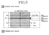
- Figure 3 is a diagram showing the forward and reverse fault regions in the zero sequence impedance plane relative to the forward and reverse fault thresholds.
- Figure 4 is a circuit diagram showing the operation of the zero sequence voltage polarized directional element of the present invention.
- Figure 5 is a circuit diagram showing the operation of a zero sequence current-polarized directional element.
- Figure 6 is a circuit diagram showing a negative sequence voltage polarized directional element.
- Figure 1 shows the sequence networks for a phase-to-ground fault, i.e. from one phase line (A, B or C phase) to ground, for a power transmission line.
- a protective relay will typically monitor all of the sequence network currents and voltages.
- a remote fault resistance 10 is shown as 3R F .
- the positive sequence network includes a positive sequence local source impedance (Z S1 ), a positive sequence line impedance (Z L1 ), and a positive sequence remote source impedance (Z R1 ), shown at 12, 14 and 16, respectively.
- a protective relay 17 is located relative to the network impedances as shown.
- the negative sequence quantities and the zero sequence quantities for a remote ground fault are also shown in Figure 1, with the relay monitoring those quantities as well.
- T Re(S1 ⁇ S2*) where * indicates a complex conjugate.
- the torque determination is accomplished by a cosine phase angle comparator.
- Z LO is the local source impedance.
- V A , V B , V C voltages are the voltages for each phase (A, B and C) of the power system signal at the relay location, while the I A , I B , I C currents are the currents for the three phases at the relay location.
- the directional element Since zero sequence current leads the zero sequence voltage if the fault is in front of the relay, and lags the zero sequence voltage if the fault is behind the relay, then when the calculated torque is negative, the directional element declares a forward fault condition (if a minimum torque threshold is exceeded) and conversely declares a reverse fault if the torque is positive (if a minimum torque is exceeded).
- such a conventional zero sequence voltage-polarized directional element is not reliable in a situation where the zero sequence local source impedance Z SO is small compared to the zero sequence line impedance Z LO , which may be the case, for instance, for remote faults on long transmission lines and strong systems.
- the conventional zero sequence directional element will not be able to reliably declare a fault condition, because the value of 3V O is so small that its measured angle is not reliable.
- the present invention while using zero sequence voltages, is capable of providing a reliable indication of direction even when the zero sequence source impedance is in fact very small compared to the zero sequence line impedance. This is accomplished by adjusting the forward and reverse threshold values, so that the calculated zero sequence impedance when there is a forward fault is below the forward threshold and when there is a reverse fault is above the reverse threshold.
- the S1 value can be increased by a value kI R Z LO , where k has a preselected value.
- the k value should be less than (Z LO + Z RO )/Z LO , in order to have a reliable S1 for reverse faults, where Z LO is the zero sequence line impedance and Z RO is the zero sequence remote source impedance.
- 2 ⁇ 0 ⁇ Re[3V 0 (1 ⁇
- the zero sequence impedance plane of Figure 2 has a reactance axis X O , referred to at 24, and a resistance axis R O , referred to at 28.
- the calculated value ⁇ 0 (equation 3 above) in the present invention is compared against adjusted forward threshold Z 0F and adjusted reverse threshold Z 0R . If ⁇ 0 is less than Z 0F , the element declares a forward fault condition, while if ⁇ 0 is greater than Z 0R , the element declares a reverse fault direction.
- the Z 0F value defines the forward zone boundary of the relay, while Z OR value defines the reverse zone boundary.
- the values of Z OR and Z OF are separated in the embodiment shown by a value of 0.1 ohm.
- the adjusted forward threshold Z OF is set to be larger than ⁇ 0F and less than the reverse threshold Z OR minus 0.1.
- the adjusted reverse threshold Z OR is set to be less than ⁇ 0R and larger than the forward threshold Z OF plus 0.1.
- the thresholds are within an impedance region boundaried by -Z SO and Z LO +Z RO , so that even if the source impedance is zero or close to it, there is still sufficient room or margin to select the two thresholds.
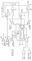
- Figure 4 shows the implementation of the above-described zero sequence directional element.
- Figure 4 includes several protective functions in addition to the basic calculation and comparison functions noted above.
- the calculation of ⁇ 0 is accomplished by element 40 in accordance with the formula (3) indicated above.
- This calculation block has inputs of 3V 0 and I R .
- the output of element 40 ( ⁇ 0 ) is compared against the forward threshold Z 0F setting by comparator 42 and against the reverse threshold Z OR by comparator 44.
- the calculation element 40 is enabled by the output of AND gate 46.
- the output of AND gate 46 is high when several conditions coexist. The first is when the magnitude of residual current I R is larger than the magnitude of the positive sequence current I 1 multiplied by a selected supervision factor a 0 . This determination is made by comparator 48. This comparison is made so as to provide security for the directional element for three-phase fault conditions on unbalanced transmission lines.
- residual current I R must be greater than a 50F element setting, the 50F element being a particular fault detection element.
- the 50F threshold is within a setting range of 0.25-5 amps for a 5 amp nominal relay.
- the comparison function is accomplished by comparator 50.
- the residual current I R must be above the 50R threshold to enable the directional element for reverse faults.
- the 50R setting range is also 0.25-5 amps for a 5 amp nominal relay.
- the comparison function for the 50R setting is carried out by comparator 51.
- the outputs from comparators 50 and 51 are applied to an OR gate 49, the output of which is applied to AND gate 46.
- a third input (NOT) to AND gate 46 is from the output of OR gate 52.
- This particular input involves another aspect of the invention to be discussed in more detail below, and is not present if the zero sequence voltage-polarized element of Figure 4 is used as the only directional element in a protective relay.
- OR gate 52 When the output of OR gate 52 is high, the output of AND gate 46 is low and the calculation element 40 is not enabled.
- the output of forward threshold comparator 42 is applied at one input to an AND gate 54.
- the output of AND gate 54 provides a forward fault indication referred to as 32VF.
- the other input to AND gate 54 is a NOT input from OR gate 56. This input is enabling (such that a high output from comparator 42 will produce a 32VF forward fault indication) when the 50F setting has been reached or when the output from OR gate 52 is low, or when there is no indication of a reverse fault.
- OR gate 56 thus provides a "clearing” or “terminate” function for a forward fault indication when a reverse fault is subsequently indicated.
- the output of comparator 44 for reverse faults is applied as one input to an AND gate 58.
- the other input (NOT) to AND gate 58 is from OR gate 60.
- the output from OR gate 60 is low (so that the output from AND gate 58 is high when the output from comparator 44 is high, indicating a reverse fault) when the 5OR reverse threshold setting has been exceeded, or when the output of OR gate 52 is low, and when there is no subsequent indication of a forward fault from AND gate 54.
- the output of OR gate 60 is low (so that the NOT input is high) and the comparator 44 output is high, the output of AND gate 58 goes high and there is provided a signal indication of a reverse fault (32VR) on line 55. Should a subsequent forward fault indication be produced, the output of OR gate 60 will go high, blocking AND gate 58 and "clearing" the reverse fault indication 32VR.
- the zero sequence voltage-polarized directional element of Figure 4 using the two separate modified thresholds for forward and reverse faults, provides a reliable indication of fault conditions even for remote faults with strong local sources (small zero sequence source impedance).
- Figure 5 shows a zero sequence current-polarized directional element which could be used in such an arrangement.
- a calculation is made by element 70, multiplying the residual current I R and an external polarizing source current (I POL ) and obtaining the real portion of the value thereof.
- This resulting calculated value is applied to two comparators 72 and 74.
- Comparator 72 compares the calculated value with a +0.0625 value for a 5 amp nominal relay. If the calculated value is greater than the threshold, the high output of comparator 72 is applied to an AND gate 75, which produces a 32IF forward fault indication on line 75. The forward fault indication can be cleared, however, by a subsequent reverse fault indication from AND gate 78.
- comparator 74 the calculated value from calculator 70 is compared against a -0.625 reverse fault threshold value. If this threshold value is less (more negative) than the calculated value, a high output from comparator 74 is applied to AND gate 78. The AND gate 78 is cleared by a forward fault indication from AND gate 75.
- the calculation elements have several threshold operating requirements. First, the absolute value of I R must exceed pre-established settings. This is established by comparator 84. Further, the absolute value of the polarizing current I POL must exceed 0.25 amps, as established by comparator 85. Further, there must be substantially no residual current in the parallel phase line, as established by comparator 88 and at the same time, there should be a lack of assertion of the IMBL input which is for the detection of zero sequence source isolation, which may cause misoperation of the current-polarized directional element.
- Comparators 96, 98 and 100 provide specific qualifying protection to enable the calculation element 90.
- the negative sequence current must exceed a certain minimal threshold a 2 (I 1 ), where a 2 is a selected constant, and I 1 is the positive sequence current.
- the negative sequence current also must have minimum values for forward and reverse fault determinations, respectively.
- An OR gate 97 and AND gate 102 complete the enabling protection feature.
- AND gate 102 is also responsive to the lack of a signal from OR gate 103.
- the negative sequence directional element of figure 6 also features an output "clearing" capability through OR gates 104, 106 and AND gates 108, 110, for the respective forward and reverse direction outputs, similar to that for the circuit elements of Figures 4 and 5.
- the zero sequence current-polarized directional element ( Figure 5) is first in line; if this individual element makes a directional decision, then the other two elements do not run.
- This arrangement is implemented, for instance, by the 32IF and 32IR inputs being applied to OR gate 52 in Figure 4 and OR gate 103 in Figure 6, which effectively disables the impedance calculation element in those circuits.
- the sequence of operation of the individual directional elements comprising the universal directional element of the present invention is (1) the zero sequence current-polarized directional element, (2) the negative sequence directional element and (3) the zero sequence voltage-polarized directional element.
- This sequential arrangement has advantages in many situations, such as when the voltage and current values necessary for operation of a particular directional element may not be available in a selected application. For instance, in a situation where the positive sequence source is removed from the power system, the negative sequence source is removed as well. If the directional element in the relay is a negative sequence element, then the relay cannot make a directional decision because the negative sequence quantities are not available.
- the invention is appropriately referred to as an adaptive or universal directional element for unbalanced faults, utilizing three individual directional elements in a particular order. It should be understood, however, that a different order than that specified above may be utilized, or in some cases two elements or more than three elements could be used.
- a new zero sequence directional element which provides additional directional assurance relative to conventional zero sequence elements and which has certain advantages over comparable negative sequence directional elements as well.
- different individual directional elements are combined in a particular order to provide an adaptive or universal directional element capability.
Landscapes
- Emergency Protection Circuit Devices (AREA)
- Details Of Aerials (AREA)
- Control Of Motors That Do Not Use Commutators (AREA)
- Semiconductor Lasers (AREA)
- Locating Faults (AREA)
- Inspection Of Paper Currency And Valuable Securities (AREA)
Priority Applications (1)
| Application Number | Priority Date | Filing Date | Title |
|---|---|---|---|
| EP99302513A EP0932235B1 (de) | 1995-10-20 | 1996-10-11 | Richtungsrelais |
Applications Claiming Priority (2)
| Application Number | Priority Date | Filing Date | Title |
|---|---|---|---|
| US08/546,224 US5694281A (en) | 1995-10-20 | 1995-10-20 | Zero sequence voltage-polarized directional element for protective relays |
| US546224 | 1995-10-20 |
Related Child Applications (1)
| Application Number | Title | Priority Date | Filing Date |
|---|---|---|---|
| EP99302513A Division EP0932235B1 (de) | 1995-10-20 | 1996-10-11 | Richtungsrelais |
Publications (3)
| Publication Number | Publication Date |
|---|---|
| EP0769836A2 true EP0769836A2 (de) | 1997-04-23 |
| EP0769836A3 EP0769836A3 (de) | 1997-06-18 |
| EP0769836B1 EP0769836B1 (de) | 2002-09-04 |
Family
ID=24179417
Family Applications (2)
| Application Number | Title | Priority Date | Filing Date |
|---|---|---|---|
| EP96307413A Expired - Lifetime EP0769836B1 (de) | 1995-10-20 | 1996-10-11 | Richtungsrelais |
| EP99302513A Expired - Lifetime EP0932235B1 (de) | 1995-10-20 | 1996-10-11 | Richtungsrelais |
Family Applications After (1)
| Application Number | Title | Priority Date | Filing Date |
|---|---|---|---|
| EP99302513A Expired - Lifetime EP0932235B1 (de) | 1995-10-20 | 1996-10-11 | Richtungsrelais |
Country Status (8)
| Country | Link |
|---|---|
| US (1) | US5694281A (de) |
| EP (2) | EP0769836B1 (de) |
| CN (2) | CN1331290C (de) |
| AT (2) | ATE223626T1 (de) |
| DE (2) | DE69623406T2 (de) |
| DK (2) | DK0769836T3 (de) |
| ES (2) | ES2182458T3 (de) |
| PT (2) | PT769836E (de) |
Cited By (5)
| Publication number | Priority date | Publication date | Assignee | Title |
|---|---|---|---|---|
| EP1331715A1 (de) * | 2002-01-28 | 2003-07-30 | Kabushiki Kaisha Toshiba | Digitaler Richtungsrelais |
| WO2008049946A1 (es) | 2006-10-25 | 2008-05-02 | Universidad Del Pais Vasco-Euskal Herriko Unibertsitatea | Sistema de protección de línea eléctrica para determinar el sentido en el que se produce una falta |
| WO2008099037A1 (es) | 2007-02-14 | 2008-08-21 | Universidad Del Pais Vasco-Euskal Herriko Unibertsitatea | Protección de línea eléctrica para determinar el sentido en el que se produce una falta |
| CN102646967A (zh) * | 2012-05-04 | 2012-08-22 | 清华大学 | 一种配电线路不对称故障继电保护方法 |
| CN102692571A (zh) * | 2012-04-27 | 2012-09-26 | 国电南瑞科技股份有限公司 | 变压器相过流保护方向元件的判别方法 |
Families Citing this family (42)
| Publication number | Priority date | Publication date | Assignee | Title |
|---|---|---|---|---|
| US6573726B1 (en) * | 2000-05-02 | 2003-06-03 | Schweitzer Engineering Laboratories, Inc. | Sensitive ground fault detection system for use in compensated electric power distribution networks |
| US6738719B2 (en) * | 2001-09-13 | 2004-05-18 | Abb Power Automation Ltd. | Crossover fault classification for power lines with parallel circuits |
| US6741943B2 (en) * | 2001-09-13 | 2004-05-25 | Abb Power Automation Ltd. | Crossover fault classification for power lines with parallel circuits |
| US6721670B2 (en) | 2001-09-13 | 2004-04-13 | Abb Power Automation Ltd. | Crossover fault classification for power lines with parallel circuits |
| US6760670B2 (en) * | 2001-09-13 | 2004-07-06 | Abb Power Automation Ltd. | Crossover fault classification for power lines with parallel circuits |
| US6721671B2 (en) * | 2001-10-24 | 2004-04-13 | Schweitzer Engineering Laboratories, Inc. | Directional element to determine faults on ungrounded power systems |
| US6785105B2 (en) * | 2002-08-05 | 2004-08-31 | Schweitzer Engineering Laboratories, Inc. | Ground fault detection system for ungrounded power systems |
| WO2006124743A1 (en) * | 2005-05-13 | 2006-11-23 | Abb Technology Ag | Method and apparatus for improving operational reliability during a loss of a phase voltage |
| CN100409019C (zh) * | 2005-06-10 | 2008-08-06 | 北京四方继保自动化股份有限公司 | 具有负序反方向闭锁的零序方向测量元件 |
| CN100338472C (zh) * | 2005-06-10 | 2007-09-19 | 北京四方继保自动化股份有限公司 | 具有零序电压补偿的零序方向测量方法 |
| CN100365900C (zh) * | 2005-10-13 | 2008-01-30 | 西安交通大学 | 一种电力系统高压输电线路零序方向的保护方法 |
| CN100444493C (zh) * | 2005-12-28 | 2008-12-17 | 长沙理工大学 | 一种自适应接地阻抗继电器 |
| US7856327B2 (en) * | 2007-10-09 | 2010-12-21 | Schweitzer Engineering Laboratories, Inc. | State and topology processor |
| US8321162B2 (en) * | 2007-10-09 | 2012-11-27 | Schweitzer Engineering Laboratories Inc | Minimizing circulating current using time-aligned data |
| US8405944B2 (en) * | 2007-10-09 | 2013-03-26 | Schweitzer Engineering Laboratories Inc | Distributed bus differential protection using time-stamped data |
| US8072715B2 (en) * | 2008-07-16 | 2011-12-06 | Huntington Ingalls Incorporated | Method, apparatus and computer program product for fault protection |
| EP2476002B1 (de) * | 2009-09-09 | 2015-05-27 | Siemens Aktiengesellschaft | Fehlererkennung in energieversorgungsnetzen mit ungeerdetem oder gelöschtem sternpunkt |
| US8706309B2 (en) | 2010-04-10 | 2014-04-22 | Schweitzer Engineering Laboratories Inc | Systems and method for obtaining a load model and related parameters based on load dynamics |
| US9008850B2 (en) | 2010-08-24 | 2015-04-14 | Schweitzer Engineering Laboratories, Inc. | Systems and methods for under-frequency blackout protection |
| US10310480B2 (en) | 2010-08-24 | 2019-06-04 | Schweitzer Engineering Laboratories, Inc. | Systems and methods for under-frequency blackout protection |
| US8965592B2 (en) | 2010-08-24 | 2015-02-24 | Schweitzer Engineering Laboratories, Inc. | Systems and methods for blackout protection |
| US8792217B2 (en) | 2010-09-15 | 2014-07-29 | Schweitzer Engineering Laboratories Inc | Systems and methods for protection of components in electrical power delivery systems |
| US9128130B2 (en) | 2011-09-15 | 2015-09-08 | Schweitzer Engineering Laboratories, Inc. | Systems and methods for synchronizing distributed generation systems |
| US10261567B2 (en) | 2013-05-21 | 2019-04-16 | Schweitzer Engineering Laboratories, Inc. | Automatically configurable intelligent electronic device |
| US9128140B2 (en) | 2013-09-16 | 2015-09-08 | Schweitzer Engineering Laboratories, Inc. | Detection of a fault in an ungrounded electric power distribution system |
| CN103595032B (zh) * | 2013-11-21 | 2018-01-23 | 国家电网公司 | 用于不换位同塔双回线路的零序方向元件闭锁的方法 |
| CN104142452B (zh) * | 2014-07-28 | 2016-09-28 | 国家电网公司 | 基于两个单相电压互感器提取配电网单相接地时的零序电压的方法 |
| CA2969546C (en) | 2014-12-01 | 2018-10-02 | S&C Electric Company | Fault detection and direction determination |
| US9798342B2 (en) | 2015-02-23 | 2017-10-24 | Schweitzer Engineering Laboratories, Inc. | Detection and correction of fault induced delayed voltage recovery |
| CN105337256B (zh) * | 2015-11-23 | 2018-07-06 | 西安交通大学 | 一种用于同塔双回线路的零序电压补偿元件闭锁方法 |
| US9906041B2 (en) | 2016-03-16 | 2018-02-27 | Schweitzer Engineering Laboratories, Inc. | Decentralized generator control |
| US9912158B2 (en) | 2016-03-16 | 2018-03-06 | Schweitzer Engineering Laboratories, Inc. | Decentralized generator control |
| US10135250B2 (en) | 2016-05-25 | 2018-11-20 | Schweitzer Engineering Laboratories, Inc. | Inertia compensated load tracking in electrical power systems |
| US10312694B2 (en) | 2017-06-23 | 2019-06-04 | Schweitzer Engineering Laboratories, Inc. | Mode-based output synchronization using relays and a common time source |
| WO2019139973A1 (en) * | 2018-01-09 | 2019-07-18 | Rensselaer Polytechnic Institute | Temporary overvoltage and ground fault overvoltage protection based on arrester current measurement and analysis |
| US10476268B2 (en) | 2018-02-09 | 2019-11-12 | Schweitzer Engineering Laboratories, Inc. | Optimized decoupling and load shedding |
| US10381835B1 (en) | 2018-02-09 | 2019-08-13 | Schweitzer Engineering Laboratories, Inc. | Electric power generator selection, shedding, and runback for power system stability |
| CN113687267B (zh) * | 2021-09-14 | 2023-08-04 | 广东电网有限责任公司 | 一种高阻接地故障方向检测方法、系统、设备及存储介质 |
| US12244135B2 (en) | 2021-12-01 | 2025-03-04 | Schweitzer Engineering Laboratories, Inc. | Differential protection using instrument transformer signal transducers |
| US12418168B2 (en) | 2023-01-25 | 2025-09-16 | Schweitzer Engineering Laboratories, Inc. | High-impedance differential protection using a diversity of signals |
| US12218694B2 (en) | 2023-04-05 | 2025-02-04 | Schweitzer Engineering Laboratories, Inc. | Bit pattern sequence compressor |
| US12603490B2 (en) | 2023-11-01 | 2026-04-14 | Schweitzer Engineering Laboratories, Inc. | Protective device with multi-channel line current differential protection |
Family Cites Families (5)
| Publication number | Priority date | Publication date | Assignee | Title |
|---|---|---|---|---|
| US4453191A (en) * | 1982-07-29 | 1984-06-05 | General Electric Company | Overvoltage directional relay |
| US4686601A (en) * | 1985-10-02 | 1987-08-11 | General Electric Company | Ground distance relay for AC power transmission line protection |
| US5349490A (en) * | 1992-10-15 | 1994-09-20 | Schweitzer Engineering Laboratories, Inc. | Negative sequence directional element for a relay useful in protecting power transmission lines |
| CN2149042Y (zh) * | 1993-03-04 | 1993-12-08 | 邹翀宇 | 三相电源反相相序自动调整器 |
| CN2172911Y (zh) * | 1993-12-28 | 1994-07-27 | 北京开关厂通用电气自动化研究所 | 功率方向继电器 |
-
1995
- 1995-10-20 US US08/546,224 patent/US5694281A/en not_active Expired - Lifetime
-
1996
- 1996-10-11 PT PT96307413T patent/PT769836E/pt unknown
- 1996-10-11 AT AT96307413T patent/ATE223626T1/de not_active IP Right Cessation
- 1996-10-11 DE DE69623406T patent/DE69623406T2/de not_active Expired - Fee Related
- 1996-10-11 DE DE69623350T patent/DE69623350T2/de not_active Expired - Fee Related
- 1996-10-11 AT AT99302513T patent/ATE223117T1/de not_active IP Right Cessation
- 1996-10-11 ES ES99302513T patent/ES2182458T3/es not_active Expired - Lifetime
- 1996-10-11 DK DK96307413T patent/DK0769836T3/da active
- 1996-10-11 EP EP96307413A patent/EP0769836B1/de not_active Expired - Lifetime
- 1996-10-11 CN CNB001338889A patent/CN1331290C/zh not_active Expired - Fee Related
- 1996-10-11 EP EP99302513A patent/EP0932235B1/de not_active Expired - Lifetime
- 1996-10-11 ES ES96307413T patent/ES2182954T3/es not_active Expired - Lifetime
- 1996-10-11 DK DK99302513T patent/DK0932235T3/da active
- 1996-10-11 PT PT99302513T patent/PT932235E/pt unknown
- 1996-10-18 CN CN96112787A patent/CN1068145C/zh not_active Expired - Fee Related
Cited By (12)
| Publication number | Priority date | Publication date | Assignee | Title |
|---|---|---|---|---|
| EP1331715A1 (de) * | 2002-01-28 | 2003-07-30 | Kabushiki Kaisha Toshiba | Digitaler Richtungsrelais |
| US6989977B2 (en) | 2002-01-28 | 2006-01-24 | Kabushiki Kaisha Toshiba | Digital directional relay |
| EP1804357A1 (de) * | 2002-01-28 | 2007-07-04 | Kabushiki Kaisha Toshiba | Digitaler Richtungsrelais |
| EP1804358A1 (de) * | 2002-01-28 | 2007-07-04 | Kabushiki Kaisha Toshiba | Digitaler Richtungsrelais |
| WO2008049946A1 (es) | 2006-10-25 | 2008-05-02 | Universidad Del Pais Vasco-Euskal Herriko Unibertsitatea | Sistema de protección de línea eléctrica para determinar el sentido en el que se produce una falta |
| ES2323994A1 (es) * | 2006-10-25 | 2009-07-28 | Universidad Del Pais Vasco-Euskal Herriko Unibertsitatea | Siste de proteccion de linea electrica para determinar el sentido en el que se produce una falta. |
| ES2323994B1 (es) * | 2006-10-25 | 2010-05-13 | Universidad Del Pais Vasco-Euskal Herriko Unibertsitatea | Sistema de proteccion de linea electrica para determinar el sentido en el que se produce una falta. |
| WO2008099037A1 (es) | 2007-02-14 | 2008-08-21 | Universidad Del Pais Vasco-Euskal Herriko Unibertsitatea | Protección de línea eléctrica para determinar el sentido en el que se produce una falta |
| ES2308913A1 (es) * | 2007-02-14 | 2008-12-01 | Universidad Del Pais Vasco-Euskal Herriko Unibertsitatea | Proteccion de linea electrica para determinar el sentido en el que se produce una falta. |
| ES2308913B1 (es) * | 2007-02-14 | 2009-10-23 | Universidad Del Pais Vasco-Euskal Herriko Unibertsitatea | Proteccion de linea electrica para determinar el sentido en el que se produce una falta. |
| CN102692571A (zh) * | 2012-04-27 | 2012-09-26 | 国电南瑞科技股份有限公司 | 变压器相过流保护方向元件的判别方法 |
| CN102646967A (zh) * | 2012-05-04 | 2012-08-22 | 清华大学 | 一种配电线路不对称故障继电保护方法 |
Also Published As
| Publication number | Publication date |
|---|---|
| EP0932235B1 (de) | 2002-08-28 |
| CN1068145C (zh) | 2001-07-04 |
| DE69623406T2 (de) | 2003-05-22 |
| DE69623350T2 (de) | 2003-04-10 |
| EP0932235A3 (de) | 2000-03-08 |
| ATE223626T1 (de) | 2002-09-15 |
| PT932235E (pt) | 2002-11-29 |
| DE69623350D1 (de) | 2002-10-02 |
| ES2182954T3 (es) | 2003-03-16 |
| DK0932235T3 (da) | 2002-10-07 |
| DE69623406D1 (de) | 2002-10-10 |
| DK0769836T3 (da) | 2002-10-07 |
| EP0769836B1 (de) | 2002-09-04 |
| ES2182458T3 (es) | 2003-03-01 |
| CN1331290C (zh) | 2007-08-08 |
| CN1154586A (zh) | 1997-07-16 |
| PT769836E (pt) | 2002-12-31 |
| ATE223117T1 (de) | 2002-09-15 |
| EP0932235A2 (de) | 1999-07-28 |
| US5694281A (en) | 1997-12-02 |
| CN1332506A (zh) | 2002-01-23 |
| EP0769836A3 (de) | 1997-06-18 |
Similar Documents
| Publication | Publication Date | Title |
|---|---|---|
| EP0769836A2 (de) | Richtungsrelais | |
| US5365396A (en) | Negative sequence directional element for a relay useful in protecting power transmission lines | |
| US6603298B2 (en) | System for estimating the frequency of the power signal on a power transmission line | |
| US5515227A (en) | Fault identification system for use in protective relays for power transmission lines | |
| EP1446675B1 (de) | Bestimmen elektrischer fehler in unterirdischen stromversorgungssystemen mit einem richtelement | |
| US6785105B2 (en) | Ground fault detection system for ungrounded power systems | |
| US5796258A (en) | Adaptive quadrilateral characteristic distance relay | |
| US6525543B1 (en) | Fault type selection system for identifying faults in an electric power system | |
| US6661630B1 (en) | Distance relay for protection of transmission line having minimized reactance effect | |
| US5808845A (en) | System for preventing sympathetic tripping in a power system | |
| JP2000125462A (ja) | 距離継電器 | |
| US5883578A (en) | Loss of potential determination for use in protective relays for electric power systems | |
| US20060152866A1 (en) | System for maintaining fault-type selection during an out-of-step condition | |
| JP2004080839A (ja) | 地絡方向継電器および地絡方向継電装置 | |
| Kiaei et al. | Current-only directional overcurrent protection using postfault current | |
| US5325061A (en) | Computationally-efficient distance relay for power transmission lines | |
| EP0202756B1 (de) | Schutzeinrichtung | |
| JP3829614B2 (ja) | デジタル形保護継電装置 | |
| JP2957187B2 (ja) | 計器用変圧器の2次回路断線検出装置 | |
| CN100426616C (zh) | 保护继电装置 | |
| US6298309B1 (en) | Current based frequency tracking method and apparatus | |
| JP3191527B2 (ja) | 一相断線常時監視方式 | |
| JP2001103656A (ja) | 母線保護継電装置 | |
| US20030011951A1 (en) | System for preventing overreach of protection for series compensated power lines | |
| JP3746493B2 (ja) | 比率差動継電装置 |
Legal Events
| Date | Code | Title | Description |
|---|---|---|---|
| PUAI | Public reference made under article 153(3) epc to a published international application that has entered the european phase |
Free format text: ORIGINAL CODE: 0009012 |
|
| AK | Designated contracting states |
Kind code of ref document: A2 Designated state(s): AT BE CH DE DK ES FI FR GB GR IE IT LI LU MC NL PT SE |
|
| PUAL | Search report despatched |
Free format text: ORIGINAL CODE: 0009013 |
|
| AK | Designated contracting states |
Kind code of ref document: A3 Designated state(s): AT BE CH DE DK ES FI FR GB GR IE IT LI LU MC NL PT SE |
|
| 17P | Request for examination filed |
Effective date: 19970829 |
|
| 17Q | First examination report despatched |
Effective date: 19981202 |
|
| GRAG | Despatch of communication of intention to grant |
Free format text: ORIGINAL CODE: EPIDOS AGRA |
|
| GRAG | Despatch of communication of intention to grant |
Free format text: ORIGINAL CODE: EPIDOS AGRA |
|
| GRAG | Despatch of communication of intention to grant |
Free format text: ORIGINAL CODE: EPIDOS AGRA |
|
| GRAH | Despatch of communication of intention to grant a patent |
Free format text: ORIGINAL CODE: EPIDOS IGRA |
|
| GRAH | Despatch of communication of intention to grant a patent |
Free format text: ORIGINAL CODE: EPIDOS IGRA |
|
| GRAA | (expected) grant |
Free format text: ORIGINAL CODE: 0009210 |
|
| AK | Designated contracting states |
Kind code of ref document: B1 Designated state(s): AT BE CH DE DK ES FI FR GB GR IE IT LI LU MC NL PT SE |
|
| REF | Corresponds to: |
Ref document number: 223626 Country of ref document: AT Date of ref document: 20020915 Kind code of ref document: T |
|
| REG | Reference to a national code |
Ref country code: GB Ref legal event code: FG4D |
|
| REG | Reference to a national code |
Ref country code: CH Ref legal event code: EP |
|
| REG | Reference to a national code |
Ref country code: CH Ref legal event code: NV Representative=s name: E. BLUM & CO. PATENTANWAELTE |
|
| REG | Reference to a national code |
Ref country code: IE Ref legal event code: FG4D |
|
| REG | Reference to a national code |
Ref country code: DK Ref legal event code: T3 |
|
| REF | Corresponds to: |
Ref document number: 69623406 Country of ref document: DE Date of ref document: 20021010 |
|
| REG | Reference to a national code |
Ref country code: PT Ref legal event code: SC4A Free format text: AVAILABILITY OF NATIONAL TRANSLATION Effective date: 20021030 |
|
| REG | Reference to a national code |
Ref country code: GR Ref legal event code: EP Ref document number: 20020404104 Country of ref document: GR |
|
| ET | Fr: translation filed | ||
| REG | Reference to a national code |
Ref country code: ES Ref legal event code: FG2A Ref document number: 2182954 Country of ref document: ES Kind code of ref document: T3 |
|
| PLBE | No opposition filed within time limit |
Free format text: ORIGINAL CODE: 0009261 |
|
| STAA | Information on the status of an ep patent application or granted ep patent |
Free format text: STATUS: NO OPPOSITION FILED WITHIN TIME LIMIT |
|
| 26N | No opposition filed |
Effective date: 20030605 |
|
| PGFP | Annual fee paid to national office [announced via postgrant information from national office to epo] |
Ref country code: IE Payment date: 20030929 Year of fee payment: 8 |
|
| PGFP | Annual fee paid to national office [announced via postgrant information from national office to epo] |
Ref country code: GR Payment date: 20030930 Year of fee payment: 8 |
|
| PGFP | Annual fee paid to national office [announced via postgrant information from national office to epo] |
Ref country code: MC Payment date: 20031001 Year of fee payment: 8 |
|
| PGFP | Annual fee paid to national office [announced via postgrant information from national office to epo] |
Ref country code: PT Payment date: 20031003 Year of fee payment: 8 |
|
| PGFP | Annual fee paid to national office [announced via postgrant information from national office to epo] |
Ref country code: BE Payment date: 20031015 Year of fee payment: 8 |
|
| PGFP | Annual fee paid to national office [announced via postgrant information from national office to epo] |
Ref country code: LU Payment date: 20031024 Year of fee payment: 8 |
|
| PGFP | Annual fee paid to national office [announced via postgrant information from national office to epo] |
Ref country code: DK Payment date: 20031027 Year of fee payment: 8 |
|
| PGFP | Annual fee paid to national office [announced via postgrant information from national office to epo] |
Ref country code: AT Payment date: 20031030 Year of fee payment: 8 |
|
| PGFP | Annual fee paid to national office [announced via postgrant information from national office to epo] |
Ref country code: NL Payment date: 20031031 Year of fee payment: 8 |
|
| PG25 | Lapsed in a contracting state [announced via postgrant information from national office to epo] |
Ref country code: LU Free format text: LAPSE BECAUSE OF NON-PAYMENT OF DUE FEES Effective date: 20041011 Ref country code: IE Free format text: LAPSE BECAUSE OF NON-PAYMENT OF DUE FEES Effective date: 20041011 Ref country code: AT Free format text: LAPSE BECAUSE OF NON-PAYMENT OF DUE FEES Effective date: 20041011 |
|
| PG25 | Lapsed in a contracting state [announced via postgrant information from national office to epo] |
Ref country code: MC Free format text: LAPSE BECAUSE OF NON-PAYMENT OF DUE FEES Effective date: 20041031 Ref country code: BE Free format text: LAPSE BECAUSE OF NON-PAYMENT OF DUE FEES Effective date: 20041031 |
|
| PG25 | Lapsed in a contracting state [announced via postgrant information from national office to epo] |
Ref country code: DK Free format text: LAPSE BECAUSE OF NON-PAYMENT OF DUE FEES Effective date: 20041101 |
|
| PG25 | Lapsed in a contracting state [announced via postgrant information from national office to epo] |
Ref country code: PT Free format text: LAPSE BECAUSE OF NON-PAYMENT OF DUE FEES Effective date: 20050411 |
|
| BERE | Be: lapsed |
Owner name: *SCHWEITZER ENGINEERING LABORATORIES INC. Effective date: 20041031 |
|
| PG25 | Lapsed in a contracting state [announced via postgrant information from national office to epo] |
Ref country code: NL Free format text: LAPSE BECAUSE OF NON-PAYMENT OF DUE FEES Effective date: 20050501 |
|
| PG25 | Lapsed in a contracting state [announced via postgrant information from national office to epo] |
Ref country code: GR Free format text: LAPSE BECAUSE OF NON-PAYMENT OF DUE FEES Effective date: 20050504 |
|
| REG | Reference to a national code |
Ref country code: DK Ref legal event code: EBP |
|
| REG | Reference to a national code |
Ref country code: PT Ref legal event code: MM4A Free format text: LAPSE DUE TO NON-PAYMENT OF FEES Effective date: 20050411 |
|
| NLV4 | Nl: lapsed or anulled due to non-payment of the annual fee |
Effective date: 20050501 |
|
| REG | Reference to a national code |
Ref country code: IE Ref legal event code: MM4A |
|
| PGFP | Annual fee paid to national office [announced via postgrant information from national office to epo] |
Ref country code: GB Payment date: 20061002 Year of fee payment: 11 |
|
| PGFP | Annual fee paid to national office [announced via postgrant information from national office to epo] |
Ref country code: ES Payment date: 20061011 Year of fee payment: 11 Ref country code: CH Payment date: 20061011 Year of fee payment: 11 |
|
| PGFP | Annual fee paid to national office [announced via postgrant information from national office to epo] |
Ref country code: SE Payment date: 20061017 Year of fee payment: 11 Ref country code: FI Payment date: 20061017 Year of fee payment: 11 |
|
| PGFP | Annual fee paid to national office [announced via postgrant information from national office to epo] |
Ref country code: IT Payment date: 20061031 Year of fee payment: 11 |
|
| PGFP | Annual fee paid to national office [announced via postgrant information from national office to epo] |
Ref country code: DE Payment date: 20061227 Year of fee payment: 11 |
|
| REG | Reference to a national code |
Ref country code: CH Ref legal event code: PFA Owner name: SCHWEITZER ENGINEERING LABORATORIES, INC. Free format text: SCHWEITZER ENGINEERING LABORATORIES, INC.#2350 NORTHEAST HOPKINS COURT#PULLMANN, WA 99163 (US) -TRANSFER TO- SCHWEITZER ENGINEERING LABORATORIES, INC.#2350 NORTHEAST HOPKINS COURT#PULLMANN, WA 99163 (US) |
|
| BERE | Be: lapsed |
Owner name: *SCHWEITZER ENGINEERING LABORATORIES INC. Effective date: 20041031 |
|
| EUG | Se: european patent has lapsed | ||
| GBPC | Gb: european patent ceased through non-payment of renewal fee |
Effective date: 20071011 |
|
| REG | Reference to a national code |
Ref country code: CH Ref legal event code: PL |
|
| PG25 | Lapsed in a contracting state [announced via postgrant information from national office to epo] |
Ref country code: LI Free format text: LAPSE BECAUSE OF NON-PAYMENT OF DUE FEES Effective date: 20071031 Ref country code: FI Free format text: LAPSE BECAUSE OF NON-PAYMENT OF DUE FEES Effective date: 20071011 Ref country code: DE Free format text: LAPSE BECAUSE OF NON-PAYMENT OF DUE FEES Effective date: 20080501 Ref country code: CH Free format text: LAPSE BECAUSE OF NON-PAYMENT OF DUE FEES Effective date: 20071031 |
|
| REG | Reference to a national code |
Ref country code: FR Ref legal event code: ST Effective date: 20080630 |
|
| PG25 | Lapsed in a contracting state [announced via postgrant information from national office to epo] |
Ref country code: SE Free format text: LAPSE BECAUSE OF NON-PAYMENT OF DUE FEES Effective date: 20071012 |
|
| PGFP | Annual fee paid to national office [announced via postgrant information from national office to epo] |
Ref country code: FR Payment date: 20061012 Year of fee payment: 11 |
|
| PG25 | Lapsed in a contracting state [announced via postgrant information from national office to epo] |
Ref country code: GB Free format text: LAPSE BECAUSE OF NON-PAYMENT OF DUE FEES Effective date: 20071011 |
|
| REG | Reference to a national code |
Ref country code: ES Ref legal event code: FD2A Effective date: 20071013 |
|
| PG25 | Lapsed in a contracting state [announced via postgrant information from national office to epo] |
Ref country code: FR Free format text: LAPSE BECAUSE OF NON-PAYMENT OF DUE FEES Effective date: 20071031 Ref country code: ES Free format text: LAPSE BECAUSE OF NON-PAYMENT OF DUE FEES Effective date: 20071013 |
|
| PG25 | Lapsed in a contracting state [announced via postgrant information from national office to epo] |
Ref country code: IT Free format text: LAPSE BECAUSE OF NON-PAYMENT OF DUE FEES Effective date: 20071011 |