EP0770038B1 - Gerät zur trinkwasseraufbereitung zum ortsveränderlichen einsatz - Google Patents
Gerät zur trinkwasseraufbereitung zum ortsveränderlichen einsatz Download PDFInfo
- Publication number
- EP0770038B1 EP0770038B1 EP95924855A EP95924855A EP0770038B1 EP 0770038 B1 EP0770038 B1 EP 0770038B1 EP 95924855 A EP95924855 A EP 95924855A EP 95924855 A EP95924855 A EP 95924855A EP 0770038 B1 EP0770038 B1 EP 0770038B1
- Authority
- EP
- European Patent Office
- Prior art keywords
- lamp
- water container
- filter cartridge
- water tank
- filter
- Prior art date
- Legal status (The legal status is an assumption and is not a legal conclusion. Google has not performed a legal analysis and makes no representation as to the accuracy of the status listed.)
- Expired - Lifetime
Links
Images

Classifications
-
- C—CHEMISTRY; METALLURGY
- C02—TREATMENT OF WATER, WASTE WATER, SEWAGE, OR SLUDGE
- C02F—TREATMENT OF WATER, WASTE WATER, SEWAGE, OR SLUDGE
- C02F1/00—Treatment of water, waste water, or sewage
- C02F1/30—Treatment of water, waste water, or sewage by irradiation
- C02F1/32—Treatment of water, waste water, or sewage by irradiation with ultraviolet light
- C02F1/325—Irradiation devices or lamp constructions
-
- C—CHEMISTRY; METALLURGY
- C02—TREATMENT OF WATER, WASTE WATER, SEWAGE, OR SLUDGE
- C02F—TREATMENT OF WATER, WASTE WATER, SEWAGE, OR SLUDGE
- C02F9/00—Multistage treatment of water, waste water or sewage
- C02F9/20—Portable or detachable small-scale multistage treatment devices, e.g. point of use or laboratory water purification systems
-
- C—CHEMISTRY; METALLURGY
- C02—TREATMENT OF WATER, WASTE WATER, SEWAGE, OR SLUDGE
- C02F—TREATMENT OF WATER, WASTE WATER, SEWAGE, OR SLUDGE
- C02F2201/00—Apparatus for treatment of water, waste water or sewage
- C02F2201/32—Details relating to UV-irradiation devices
- C02F2201/322—Lamp arrangement
- C02F2201/3228—Units having reflectors, e.g. coatings, baffles, plates, mirrors
-
- C—CHEMISTRY; METALLURGY
- C02—TREATMENT OF WATER, WASTE WATER, SEWAGE, OR SLUDGE
- C02F—TREATMENT OF WATER, WASTE WATER, SEWAGE, OR SLUDGE
- C02F2201/00—Apparatus for treatment of water, waste water or sewage
- C02F2201/32—Details relating to UV-irradiation devices
- C02F2201/326—Lamp control systems
Definitions
- the invention relates to a device for drinking water treatment for portable use with an interchangeable one Filter cartridge, an ultraviolet (UV) emitting light Lamp, a raw water tank and a pure water tank, being filled with water into the pipe water tank Gravity through the filter cartridge in the Clean water tank is running.
- UV ultraviolet
- Such table or travel devices are used depending on the one used Filters for cleaning the water of odor and Flavorings, other impurities as well existing microorganisms.
- Filters for cleaning the water of odor and Flavorings, other impurities as well existing microorganisms.
- filter materials in particular activated carbon, ion exchangers, zeolites or Molecular sieves used.
- the UV radiation causes Disinfection.
- a device of this type is from the British patent application 2 271 106 known.
- This is rather unwieldy when Transport and has inadequate process control and thus a high power consumption, so that an operation with commercially available batteries are out of the question.
- the UV lamp lies under the clean water tank and shines through a quartz window in the bottom of the container from below in this inside. Such a glass shelf can leak become and poses hygienic problems. Because of the Radiation direction of the lamp upwards are special Safety precautions required to avoid that the User looks into the lamp and thereby damages the eyes can take.
- the invention has for its object a small, to create compact and battery powered device that is better protected against eye damage to the user.
- This task is started from a device Drinking water treatment of the type described in the introduction solved according to the invention in that the UV lamp over the Clean water tank open at the top is arranged and shines directly into it. So it is not more necessary with the help of moving or changeable Shields work because the lamp shines down and can be covered permanently. It can be a simple container made of basically any material be, the radiation effect significantly improved can be if the inner surfaces of the container reflecting ultraviolet light. Because it is special Meaning is not just the filtered water in the tank, but also the filter outlet and the last ones hanging there To sterilize water drops, it is proposed that the Filter cartridge in relation to the UV lamp so attached and is trained that you the water outlet forming lower Sieve is in the radiation range of the UV lamp.
- the arrangement of the lamp above the pure water tank offers also completely new possibilities for constructive design with a view to a small total volume during transport.
- the UV lamp Filter cartridge and electrical components for operating the UV lamp and if necessary to control and monitor the device in a unit are united, which in operation on the Clean water tank sits on top of the Carries raw water tank.
- the raw water tank from the The unit is designed to be detachable and for this purpose on its base A self-closing valve identifies that when put on on the unit opens. So the device is in essentially of three parts, with a further improvement may consist in that the assembly in one of the two Container is at least partially insertable.
- the result can be the volume of the entire device almost attributed to the volume of the pure water tank which is a great advantage when traveling.
- UV lamps tend to be contaminated of the light exit window in its disinfectant effect to subside. It is therefore suggested that one use light-sensitive sensor for monitoring. He can, as described in the example, in addition to this be used, the correct placement of the unit to monitor the clean water tank.
- Another advantageous development of the invention exists in ensuring that the device is not compatible with a used and in the worst case contaminated filter cartridge can be operated. So there will be measures proposed to monitor the filter capacity. To are input devices for entering the raw water quality and / or the type of filter cartridge used and / or the At the time of filter replacement and also one Computing arrangement to based on the entered data and the number of processing operations the filter capacity monitor and switch off when the filter is exhausted or to make this state clearly identifiable.
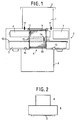
- Raw water tank 1 essentially comprises one Raw water tank 1 with lid 2 for receiving the water to be treated.
- an assembly which is a total of technical part 3 is referred to and a replaceable filter cartridge 4, a rod-shaped UV lamp 5, batteries 6 for power supply and an electronic part 7 for controlling the device functions and for voltage conversion for the UV lamp 5 contains.
- the Technical part 3 is on the edge of an open top Pure water tank 8 placed.
- This pure water tank consists of an ultraviolet light reflecting opaque material, preferably aluminum or Stainless steel. But it can also be made of a suitable plastic manufactured and at least be surface-coated on the inside.
- the filter cartridge 4 has a sleeve-shaped housing jacket, at both ends with porous filter plates 9, 10 is closed. These are made of plastic, for example or ceramics and are used to inhibit the growth of germs preferably provided with silver additives.
- the filter cartridge 4 is with a suitable, preferably granulated Filter material, for example silver activated carbon, filled. It is sealed by a sealing ring 11 into one Breakthrough of the raw water tank bottom used, so that Water can enter.
- the lower filter plate 10 through which the water runs out is above the Pure water tank 8.
- the UV lamp 5 sends a germicidal ultraviolet Light from a preferably aluminum existing light reflector 12 only downwards is emitted. As a result of the reflective inner surface of the pure water tank 8, this light also reaches the Bottom of the filter cartridge, so that the filter plate 10th and the water remaining in it is sterilized.
- the technical part 3 there is a microswitch 13 built in, when the technical part 3 is assembled correctly with the clean water tank 8 the commissioning of the device enables or in the opposite case the Preventing commissioning and possibly an additional one Warning signal triggers.
- the pollution of the UV lamp 5 will monitored by a light-sensitive sensor 14. This sits at the bottom of the technology part inside the Pure water tank. It is up towards the UV lamp darkened and only detects that from the pure water tank reflected UV light. If the lamp is dirty reduced sensor signal leads to their shutdown.
- the same sensor 14 can also serve to additionally placing the technical part 3 on the Monitor pure water tank 8.
- the sensor no longer receives ambient light. Just starting from this completely darkened state, he gives the UV lamp 5 free to switch on.
- a wire coil 15 inductively detects the presence of one for the device suitable filter cartridge. At this is a Metal strip 16 attached as a label.
- the process control is initially used once two electrodes 17, which are in the bottom of the Protect the raw water tank 1. You are in one Conductivity measuring arrangement connected and enable the automatic detection of existing in the raw water tank 1 Water. There is also the wire coil 15 Possibility of inductively conductivity in the filter cartridge 4 to measure.
- the conductivity of the activated carbon filling is from Water content in the filter cartridge depends.
- the process of water treatment is about like follows. If water is poured into the raw water tank 1, then due to the now measurable resistance between the Electrodes 17 the electronic control arrangement of the device activated. The device first waits for all water has passed through the filter cartridge 4. Then the UV lamp 5 turned on for about 10 to 60 seconds. This time is usually sufficient to contain the water Kill microorganisms. As mentioned, the Irradiated underside of the filter cartridge 4. After disinfection of the water is the user through an optical or acoustic signaling informs. Then the device switches in standby.
- the pure water tank can be used to save space during transport 8 are placed over the raw water tank 1. Its lid In this case, 2 closes the underside of the Technical part 3 (Fig. 2).
- Fig. 3 shows a further embodiment of a device according to the invention.
- the main difference to 1 is that a removable raw water tank 21 with lid 22 and a UV lamp 25 is provided, which is the plan of the container not towered over, so that all the light in here too removable clean water tank 28 falls.
- the power supply is also via batteries 6 and the electronic control is in an electronic part 33 summarized.
- the filter cartridge 24 sits eccentrically in the Technical part 23 and is partially enclosed by the UV lamp 25.
- the lower filter plate 24 a Filter cartridge is domed out to the proportion of to increase directly incident radiation.
- the technical part 23 is so compact that it does not protrude laterally from the raw water tank 21, but can be plugged into it for transport.
- the Technology part 23 is turned over and comes on Lid 22. Then the raw water tank 21 together Technical part are inserted into the pure water tank 28.
- the filter cartridge is higher than the UV lamp could be arranged to direct radiation to significantly increase the filter underside. It could also Filter cartridge should be designed so that it with its lower Part of the lamp encloses a fork.
- a microswitch 13 and a photosensitive sensor 14 is provided. Furthermore, the capacity of the filter cartridge is monitored on this device. These are at the top of the technical part, which are only at removed raw water tank 21 is accessible, two Selector switch 36 attached.
- the type of adjust the filter cartridge used for example nitrate-selective filter
- the Degree of pollution of the raw water for example very high / high / medium.
- LEDs 38 give the current operating state of the device again.
- the device determined on the basis of the passed Water fillings and taking into account the setting values at the selector switches 36 the capacity of the Filter cartridge. Is this exhausted or is due to a long business interruption (for example, 4 weeks) Contamination of the filter cannot be ruled out, so this will User signals.
- the operating sequence is designed for the device according to FIG. 3 as follows. Has the user a new filter cartridge 24 in that Inserted device, it represents the type of cartridge and the Degree of pollution of the water at the selector switches 36. Then it signals the device with a long press the button 37 to change the filter. Thereupon the errors for the capacity monitoring and the Clock of the microcontroller contained in electronics part 33 reset, which calculates the filter capacity begins.
- the user pours water for treatment in the Raw water tank 21 and briefly press the button 27 to the Start the preparation process.
- this start also automatically by means of the conductance measurement with the help of Electrodes 17 take place.
- the lamp is turned on for a required time and this sterilizes the water.
- the user is informed of the current one Operating status informed.
- Capacity counter by the amount of water filtered multiplied by the pollutant content increased.
- Capacity counter When reached the capacity limit or a certain one Filter usage time will be the user optically and / or acoustically prompted to change the filter.
Landscapes
- Health & Medical Sciences (AREA)
- Life Sciences & Earth Sciences (AREA)
- Hydrology & Water Resources (AREA)
- Engineering & Computer Science (AREA)
- Environmental & Geological Engineering (AREA)
- Water Supply & Treatment (AREA)
- Chemical & Material Sciences (AREA)
- Organic Chemistry (AREA)
- Toxicology (AREA)
- Clinical Laboratory Science (AREA)
- Physical Water Treatments (AREA)
- Water Treatment By Sorption (AREA)
Abstract
Description
- Fig. 1
- ein schematisches Schnittbild eines Tischgeräts zur Trinkwasseraufbereitung;
- Fig. 2
- eine Ansicht dieses Gerätes im raumsparenden Transportzustand in kleinerem Maßstab;
- Fig. 3
- ein schematisches Schnittbild eines anderen Tischgeräts zur Trinkwasseraufbereitung;
- Fig. 4
- eine Außenansicht eines weiteren Geräts zur Trinkwasseraufbereitung im Betriebszustand, in kleinerem Maßstab;
- Fig. 5
- das Gerät nach Figur 4 im zusammengefügten Transportzustand und
- Fig. 6
- den Reinwasserbehälter des Geräts nach Figur 4 mit Deckel als Vorratsbehälter.
- 1
- Rohwasserbehälter
- 2
- Deckel
- 3
- Technikteil
- 4
- Filterpatrone
- 5
- UV-Lampe
- 6
- Batterie
- 7
- Elektronikteil
- 8
- Reinwasserbehälter
- 9
- Filterplatte
- 10
- Filterplatte
- 11
- Dichtring
- 12
- Lichtreflektor
- 13
- Mikroschalter
- 14
- Sensor
- 15
- Drahtspule
- 16
- Metallstreifen
- 17
- Elektrode
- 21
- Rohwasserbehälter
- 22
- Deckel
- 23
- Technikteil
- 24
- Filterpatrone
- 24a
- Filterplatte
- 25
- UV-Lampe
- 26
- Dichtung
- 27
- Rückschlagventil
- 28
- Reinwasserbehälter
- 29
- Ventilteller
- 30
- Stift
- 31
- Feder
- 32
- Blattfederkontakt
- 33
- Elektronikteil
- 34
- Lichtreflektor
- 35
- Fenster
- 36
- Wahlschalter
- 37
- Taste
- 38
- Leuchtdioden
Claims (10)
- Gerät zur Trinkwasseraufbereitung zum ortsveränderlichen Einsatz mit einer auswechselbaren Filterpatrone (24), einer ultraviolettes Licht (UV) abstrahlenden Lampe (25), einem Rohwasserbehälter (21) und einem Reinwasserbehälter (28), wobei in den Rohwasserbehälter (21) eingefülltes Wasser unter Schwerkraftwirkung durch die Filterpatrone (24) in den Reinwasserbehälter (28) läuft, dadurch gekennzeichnet, daß die UV-Lampe (25) über dem oben offen ausgebildeten Reinwasserbehälter (28) angeordnet ist und unmittelbar in diesen hineinstrahlt.
- Gerät nach Anspruch 1, dadurch gekennzeichnet, daß die Filterpatrone (24) in Bezug auf die UV-Lampe (25) so angebracht und ausgebildet ist, daß ihr den Wasserauslauf bildendes unteres Sieb (24a) im Strahlungsbereich der UV-Lampe liegt.
- Gerät nach Anspruch 1, dadurch gekennzeichnet, daß die UV-Lampe (25), die Filterpatrone (24) und elektrische Komponenten (33) zum Betrieb der UV-Lampe und gegebenenfalls zur Steuerung und Überwachung des Gerätes in einer Baueinheit (23) vereinigt sind, die im Betrieb auf dem Reinwasserbehälter (28) aufsitzt und an ihrer Oberseite den Rohwasserbehälter (21) trägt.
- Gerät nach Anspruch 1, dadurch gekennzeichnet, daß die beiden Behälter (21, 28) ineinander steckbar ausgebildet sind.
- Gerät nach Anspruch 3, dadurch gekennzeichnet, daß der Rohwasserbehälter (21) von der Baueinheit (23) abnehmbar ausgebildet ist und dazu an seinem Boden ein selbstschließendes Ventil (27) aufweist, das beim Aufsetzen auf die Baueinheit (23) öffnet.
- Gerät nach Anspruch 5, dadurch gekennzeichnet, daß die Baueinheit (23) in einen der beiden Behälter (21, 28) wenigstens teilweise einfügbar ausgebildet ist.
- Gerät nach Anspruch 5, dadurch gekennzeichnet, daß die Baueinheit (23) in den Rohwasserbehälter (21) und beide Teile zusammen in den Reinwasserbehälter (28) einsteckbar sind und mit einem Deckel (22) verschlossen werden können.
- Gerät nach Anspruch 1, dadurch gekennzeichnet, daß ein lichtempfindlicher Sensor (14) zur Überwachung der Wirksamkeit der UV-Lampe (25) vorgesehen ist.
- Vorrichtung nach Anspruch 1, dadurch gekennzeichnet, daß das Vorhandensein von Wasser im Rohwasserbehälter (21) durch Leitfähigkeitsmessung zu dem Zweck erfaßt wird, die Aufbereitungsvorgänge zu zählen und/oder zu starten.
- Gerät nach Anspruch 1, dadurch gekennzeichnet, daß Eingabeorgane (36) zur Eingabe der Rohwasserqualität und/oder der Art der eingesetzten Filterpatrone und/oder des Zeitpunkts des Filterwechsels und eine Rechenanordnung vorgesehen ist, um auf der Grundlage der eingegebenen Daten und der Zahl der Aufbereitungsvorgänge die Filterkapazität zu überwachen.
Applications Claiming Priority (3)
| Application Number | Priority Date | Filing Date | Title |
|---|---|---|---|
| DE4424256A DE4424256C2 (de) | 1994-07-09 | 1994-07-09 | Trinkwasserfilter |
| DE4424256 | 1994-07-09 | ||
| PCT/DE1995/000919 WO1996001790A1 (de) | 1994-07-09 | 1995-07-07 | Gerät zur trinkwasseraufbereitung zum ortsveränderlichen einsatz |
Publications (2)
| Publication Number | Publication Date |
|---|---|
| EP0770038A1 EP0770038A1 (de) | 1997-05-02 |
| EP0770038B1 true EP0770038B1 (de) | 1999-01-20 |
Family
ID=6522755
Family Applications (1)
| Application Number | Title | Priority Date | Filing Date |
|---|---|---|---|
| EP95924855A Expired - Lifetime EP0770038B1 (de) | 1994-07-09 | 1995-07-07 | Gerät zur trinkwasseraufbereitung zum ortsveränderlichen einsatz |
Country Status (3)
| Country | Link |
|---|---|
| EP (1) | EP0770038B1 (de) |
| DE (1) | DE4424256C2 (de) |
| WO (1) | WO1996001790A1 (de) |
Families Citing this family (6)
| Publication number | Priority date | Publication date | Assignee | Title |
|---|---|---|---|---|
| DE19603884C1 (de) * | 1996-02-03 | 1997-03-20 | Klaus Dr Zucholl | Wasseraufbereitungsgerät mit Tauchfilter |
| DE19619022C2 (de) * | 1996-05-10 | 2000-07-06 | Karl F Massholder | Wassertankanordnung |
| WO2000009450A1 (en) * | 1998-08-12 | 2000-02-24 | Lifschitz Eric L | Portable water purifier with ultraviolet light source |
| DE29910816U1 (de) * | 1999-06-22 | 2000-07-13 | Wismeth, Wolfgang, 90765 Fürth | Gerät für das Entkeimen wässriger Lösungen |
| CN102557313A (zh) * | 2004-04-15 | 2012-07-11 | 特洛伊人技术公司 | 水处理设备以及在流体处理系统中使用的处理筒 |
| US9975788B2 (en) | 2013-05-21 | 2018-05-22 | Philips Lighting Holding B.V. | Optical fluid treatment device |
Family Cites Families (9)
| Publication number | Priority date | Publication date | Assignee | Title |
|---|---|---|---|---|
| DE3032996A1 (de) * | 1980-09-02 | 1982-04-15 | Wolfgang 8152 Feldkirchen-Westerham Demmert | Vorrichtung zur biologischen wasseraufbereitung |
| FR2515655A1 (en) * | 1981-11-02 | 1983-05-06 | Commissariat Energie Atomique | Ultraviolet steriliser for inlet of domestic water tank - has bottom outlet which fits several different diameters of tank inlet |
| US4968437A (en) * | 1986-05-09 | 1990-11-06 | Electrolux Water Systems, Inc. | Fluid purification system |
| DE3624414A1 (de) * | 1986-07-18 | 1988-01-28 | Michael Busch | Wasserfilter |
| US5106512A (en) * | 1991-01-30 | 1992-04-21 | Reidy James J | Portable air-water generator |
| GB9216866D0 (en) * | 1992-08-08 | 1992-09-23 | Batten Mark V | Ultra violet jug sterilization unit |
| DE4228860A1 (de) * | 1992-08-29 | 1994-03-03 | Gernot Klaus Brueck | Trinkwasseraufbereiter |
| DE9302722U1 (de) * | 1992-09-15 | 1993-07-08 | Junginger, Bernhard, 69214 Eppelheim | Vorrichtung zur Kühlmittelaufbereitung |
| DE9301688U1 (de) * | 1993-02-06 | 1993-04-29 | Jurgeleit, Ronald, Dipl.- Oek., 2800 Bremen | Vorrichtung zur Aufbereitung von Wasser |
-
1994
- 1994-07-09 DE DE4424256A patent/DE4424256C2/de not_active Expired - Fee Related
-
1995
- 1995-07-07 WO PCT/DE1995/000919 patent/WO1996001790A1/de not_active Ceased
- 1995-07-07 EP EP95924855A patent/EP0770038B1/de not_active Expired - Lifetime
Also Published As
| Publication number | Publication date |
|---|---|
| EP0770038A1 (de) | 1997-05-02 |
| WO1996001790A1 (de) | 1996-01-25 |
| DE4424256C2 (de) | 1996-08-14 |
| DE4424256A1 (de) | 1996-01-11 |
Similar Documents
| Publication | Publication Date | Title |
|---|---|---|
| DE69834105T2 (de) | Tragbares ultraviolett-wasserreinigungssystem | |
| DE10308123A1 (de) | Ozonsauggerät und Überwachungsgerät kombinierendes Wasseraufbereitungssystem | |
| US6306290B1 (en) | Water filter replacement indicator | |
| DE69521891T2 (de) | Gerät zur sterilisation von wasser | |
| CN101437760B (zh) | 自主工作的水净化设备 | |
| EP0770038B1 (de) | Gerät zur trinkwasseraufbereitung zum ortsveränderlichen einsatz | |
| DE2406299A1 (de) | Verfahren und vorrichtung zum sterilisieren von kontaktlinsen | |
| US7632397B2 (en) | Integrated portable water purifier | |
| WO2008056311A1 (en) | Water purification device and filter unit | |
| EP0808173A2 (de) | Zusammensetzung und verfahren zur vermeidung von infektionen durch respiratorische viren | |
| DE102019121621A1 (de) | Vorrichtung zum Entkeimen von Mehrweg-Behältern | |
| DE4228860A1 (de) | Trinkwasseraufbereiter | |
| JPH0352686A (ja) | 紫外線殺菌浄水器 | |
| DE102013014712B4 (de) | Mobile Wasseraufbereitungsanlage | |
| KR102035216B1 (ko) | 빗물 정화장치 | |
| DE202013009070U1 (de) | Tragbare Wasserfilterflasche | |
| WO2001055035A2 (de) | Vorrichtung zum behandeln von wasser | |
| CN209442805U (zh) | 一种水处理杂质分离装置 | |
| AT510490B1 (de) | Vorrichtung zur desinfektion von flüssigkeiten und/oder gegenständen | |
| CN206156922U (zh) | 一种自来水灭菌净化装置 | |
| JPS63175685A (ja) | 浄水器 | |
| CN203954839U (zh) | 一种水龙头净水器 | |
| EP2415717A1 (de) | Wassertransport und -reinigungsvorrichtung | |
| CN2853773Y (zh) | 带紫外线消毒的净水筒 | |
| CN2160654Y (zh) | 一种反渗透自动纯水机 |
Legal Events
| Date | Code | Title | Description |
|---|---|---|---|
| PUAI | Public reference made under article 153(3) epc to a published international application that has entered the european phase |
Free format text: ORIGINAL CODE: 0009012 |
|
| 17P | Request for examination filed |
Effective date: 19970123 |
|
| AK | Designated contracting states |
Kind code of ref document: A1 Designated state(s): ES FR GB IT |
|
| GRAG | Despatch of communication of intention to grant |
Free format text: ORIGINAL CODE: EPIDOS AGRA |
|
| 17Q | First examination report despatched |
Effective date: 19980527 |
|
| GRAG | Despatch of communication of intention to grant |
Free format text: ORIGINAL CODE: EPIDOS AGRA |
|
| GRAH | Despatch of communication of intention to grant a patent |
Free format text: ORIGINAL CODE: EPIDOS IGRA |
|
| GRAH | Despatch of communication of intention to grant a patent |
Free format text: ORIGINAL CODE: EPIDOS IGRA |
|
| GRAA | (expected) grant |
Free format text: ORIGINAL CODE: 0009210 |
|
| AK | Designated contracting states |
Kind code of ref document: B1 Designated state(s): ES FR GB IT |
|
| PG25 | Lapsed in a contracting state [announced via postgrant information from national office to epo] |
Ref country code: ES Free format text: THE PATENT HAS BEEN ANNULLED BY A DECISION OF A NATIONAL AUTHORITY Effective date: 19990120 |
|
| GBT | Gb: translation of ep patent filed (gb section 77(6)(a)/1977) |
Effective date: 19990324 |
|
| ET | Fr: translation filed | ||
| ITF | It: translation for a ep patent filed | ||
| PGFP | Annual fee paid to national office [announced via postgrant information from national office to epo] |
Ref country code: FR Payment date: 19990721 Year of fee payment: 5 |
|
| PLBE | No opposition filed within time limit |
Free format text: ORIGINAL CODE: 0009261 |
|
| STAA | Information on the status of an ep patent application or granted ep patent |
Free format text: STATUS: NO OPPOSITION FILED WITHIN TIME LIMIT |
|
| 26N | No opposition filed | ||
| PGFP | Annual fee paid to national office [announced via postgrant information from national office to epo] |
Ref country code: GB Payment date: 20000627 Year of fee payment: 6 |
|
| PG25 | Lapsed in a contracting state [announced via postgrant information from national office to epo] |
Ref country code: FR Free format text: LAPSE BECAUSE OF NON-PAYMENT OF DUE FEES Effective date: 20010330 |
|
| REG | Reference to a national code |
Ref country code: FR Ref legal event code: ST |
|
| PG25 | Lapsed in a contracting state [announced via postgrant information from national office to epo] |
Ref country code: GB Free format text: LAPSE BECAUSE OF NON-PAYMENT OF DUE FEES Effective date: 20010707 |
|
| GBPC | Gb: european patent ceased through non-payment of renewal fee |
Effective date: 20010707 |
|
| PG25 | Lapsed in a contracting state [announced via postgrant information from national office to epo] |
Ref country code: IT Free format text: LAPSE BECAUSE OF NON-PAYMENT OF DUE FEES;WARNING: LAPSES OF ITALIAN PATENTS WITH EFFECTIVE DATE BEFORE 2007 MAY HAVE OCCURRED AT ANY TIME BEFORE 2007. THE CORRECT EFFECTIVE DATE MAY BE DIFFERENT FROM THE ONE RECORDED. Effective date: 20050707 |