EP0770353A2 - Ultraschalldiagnosegerät - Google Patents
Ultraschalldiagnosegerät Download PDFInfo
- Publication number
- EP0770353A2 EP0770353A2 EP96116025A EP96116025A EP0770353A2 EP 0770353 A2 EP0770353 A2 EP 0770353A2 EP 96116025 A EP96116025 A EP 96116025A EP 96116025 A EP96116025 A EP 96116025A EP 0770353 A2 EP0770353 A2 EP 0770353A2
- Authority
- EP
- European Patent Office
- Prior art keywords
- piezo
- ultrasonic
- generating
- electric elements
- signal
- Prior art date
- Legal status (The legal status is an assumption and is not a legal conclusion. Google has not performed a legal analysis and makes no representation as to the accuracy of the status listed.)
- Withdrawn
Links
- 230000015654 memory Effects 0.000 claims abstract description 36
- 230000005540 biological transmission Effects 0.000 claims abstract description 34
- 238000009826 distribution Methods 0.000 claims abstract description 32
- 230000003068 static effect Effects 0.000 claims abstract description 15
- 238000007689 inspection Methods 0.000 claims abstract description 11
- 230000004044 response Effects 0.000 claims description 44
- 238000000034 method Methods 0.000 claims description 23
- 230000001934 delay Effects 0.000 claims description 9
- 238000006243 chemical reaction Methods 0.000 claims description 7
- 238000001914 filtration Methods 0.000 claims description 6
- 238000005070 sampling Methods 0.000 claims description 6
- 230000001131 transforming effect Effects 0.000 claims description 6
- 230000010363 phase shift Effects 0.000 claims description 2
- 230000001419 dependent effect Effects 0.000 claims 1
- 230000017531 blood circulation Effects 0.000 description 38
- 238000001228 spectrum Methods 0.000 description 25
- 230000006870 function Effects 0.000 description 11
- 230000008569 process Effects 0.000 description 11
- 230000009466 transformation Effects 0.000 description 9
- 238000003384 imaging method Methods 0.000 description 6
- 239000003086 colorant Substances 0.000 description 5
- 238000010586 diagram Methods 0.000 description 5
- 230000002194 synthesizing effect Effects 0.000 description 4
- 230000003247 decreasing effect Effects 0.000 description 3
- 238000001514 detection method Methods 0.000 description 3
- 230000008054 signal transmission Effects 0.000 description 3
- 239000007787 solid Substances 0.000 description 3
- 238000003860 storage Methods 0.000 description 3
- 230000003111 delayed effect Effects 0.000 description 2
- 238000003745 diagnosis Methods 0.000 description 2
- 239000000284 extract Substances 0.000 description 2
- 238000005259 measurement Methods 0.000 description 2
- 230000001360 synchronised effect Effects 0.000 description 2
- 238000002604 ultrasonography Methods 0.000 description 2
- NCGICGYLBXGBGN-UHFFFAOYSA-N 3-morpholin-4-yl-1-oxa-3-azonia-2-azanidacyclopent-3-en-5-imine;hydrochloride Chemical compound Cl.[N-]1OC(=N)C=[N+]1N1CCOCC1 NCGICGYLBXGBGN-UHFFFAOYSA-N 0.000 description 1
- 210000001015 abdomen Anatomy 0.000 description 1
- 230000003213 activating effect Effects 0.000 description 1
- 238000007792 addition Methods 0.000 description 1
- 230000002238 attenuated effect Effects 0.000 description 1
- 239000008280 blood Substances 0.000 description 1
- 210000004369 blood Anatomy 0.000 description 1
- 230000008859 change Effects 0.000 description 1
- 230000006835 compression Effects 0.000 description 1
- 238000007906 compression Methods 0.000 description 1
- 238000010276 construction Methods 0.000 description 1
- 230000007423 decrease Effects 0.000 description 1
- 230000000694 effects Effects 0.000 description 1
- 230000005484 gravity Effects 0.000 description 1
- 238000004519 manufacturing process Methods 0.000 description 1
- 238000003672 processing method Methods 0.000 description 1
- 230000035945 sensitivity Effects 0.000 description 1
- 238000010183 spectrum analysis Methods 0.000 description 1
- 210000001835 viscera Anatomy 0.000 description 1
- 230000000007 visual effect Effects 0.000 description 1
Images



Classifications
-
- G—PHYSICS
- G01—MEASURING; TESTING
- G01S—RADIO DIRECTION-FINDING; RADIO NAVIGATION; DETERMINING DISTANCE OR VELOCITY BY USE OF RADIO WAVES; LOCATING OR PRESENCE-DETECTING BY USE OF THE REFLECTION OR RERADIATION OF RADIO WAVES; ANALOGOUS ARRANGEMENTS USING OTHER WAVES
- G01S15/00—Systems using the reflection or reradiation of acoustic waves, e.g. sonar systems
- G01S15/88—Sonar systems specially adapted for specific applications
- G01S15/89—Sonar systems specially adapted for specific applications for mapping or imaging
- G01S15/8906—Short-range imaging systems; Acoustic microscope systems using pulse-echo techniques
- G01S15/8997—Short-range imaging systems; Acoustic microscope systems using pulse-echo techniques using synthetic aperture techniques
-
- G—PHYSICS
- G01—MEASURING; TESTING
- G01S—RADIO DIRECTION-FINDING; RADIO NAVIGATION; DETERMINING DISTANCE OR VELOCITY BY USE OF RADIO WAVES; LOCATING OR PRESENCE-DETECTING BY USE OF THE REFLECTION OR RERADIATION OF RADIO WAVES; ANALOGOUS ARRANGEMENTS USING OTHER WAVES
- G01S15/00—Systems using the reflection or reradiation of acoustic waves, e.g. sonar systems
- G01S15/88—Sonar systems specially adapted for specific applications
- G01S15/89—Sonar systems specially adapted for specific applications for mapping or imaging
- G01S15/8906—Short-range imaging systems; Acoustic microscope systems using pulse-echo techniques
- G01S15/8979—Combined Doppler and pulse-echo imaging systems
-
- G—PHYSICS
- G01—MEASURING; TESTING
- G01S—RADIO DIRECTION-FINDING; RADIO NAVIGATION; DETERMINING DISTANCE OR VELOCITY BY USE OF RADIO WAVES; LOCATING OR PRESENCE-DETECTING BY USE OF THE REFLECTION OR RERADIATION OF RADIO WAVES; ANALOGOUS ARRANGEMENTS USING OTHER WAVES
- G01S15/00—Systems using the reflection or reradiation of acoustic waves, e.g. sonar systems
- G01S15/88—Sonar systems specially adapted for specific applications
- G01S15/89—Sonar systems specially adapted for specific applications for mapping or imaging
- G01S15/8906—Short-range imaging systems; Acoustic microscope systems using pulse-echo techniques
- G01S15/8909—Short-range imaging systems; Acoustic microscope systems using pulse-echo techniques using a static transducer configuration
- G01S15/8915—Short-range imaging systems; Acoustic microscope systems using pulse-echo techniques using a static transducer configuration using a transducer array
-
- G—PHYSICS
- G01—MEASURING; TESTING
- G01S—RADIO DIRECTION-FINDING; RADIO NAVIGATION; DETERMINING DISTANCE OR VELOCITY BY USE OF RADIO WAVES; LOCATING OR PRESENCE-DETECTING BY USE OF THE REFLECTION OR RERADIATION OF RADIO WAVES; ANALOGOUS ARRANGEMENTS USING OTHER WAVES
- G01S7/00—Details of systems according to groups G01S13/00, G01S15/00, G01S17/00
- G01S7/52—Details of systems according to groups G01S13/00, G01S15/00, G01S17/00 of systems according to group G01S15/00
- G01S7/52017—Details of systems according to groups G01S13/00, G01S15/00, G01S17/00 of systems according to group G01S15/00 particularly adapted to short-range imaging
- G01S7/52053—Display arrangements
- G01S7/52057—Cathode ray tube displays
- G01S7/5206—Two-dimensional coordinated display of distance and direction; B-scan display
Definitions
- the present invention relates to an ultrasonic diagnosing apparatus for measuring a velocity of a blood flow in a living body by transmitting and receiving an ultrasonic wave, and for displaying a distribution of the velocity, and more particularly for obtaining and displaying a dynamic flow image by using a synthetic aperture.
- a color Doppler is a technique for obtaining information about the velocity of a blood flow by means of the Doppler effect.
- the results of the color Doppler technique is displayed as a pseudo-colored spatial distribution of the blood flow; this spatial distribution is superimposed on an ultrasonic tomogram of a living body, and this tomogram is obtained by an ultrasonic wave reflected from a reflector in the living body.
- the color Doppler technique has been widely used especially in the field of circulatory systems.
- a principle of the velocity measurement of the blood flow is disclosed in Japanese Laid-Open Patent Application Publication No. Sho 58-188433.
- Transmitted electric signals are converted to ultrasonic pulse waves by an array of transducers and the ultrasonic pulse waves are periodically emitted to an reflector.
- the ultrasonic pulse waves reflected from the reflector at various distances from the transducer array are sampled to detect the change in frequency of the reflected waves.
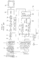
- a signal generator 1 generates a reference signal in form of a sine curve having a highly stable frequency.
- a transmission trigger generating circuit 2 detects the phase of the reference signal, and generates a timing signal synchronized with the reference signal. Further, based on this timing signal, the transmission trigger generating circuit 2 generates a group of trigger pulse waves with predetermined time delays for focusing on a predetermined focal point in the living body.
- the trigger pulse waves are amplified by transmission amplifiers 3.
- the amplified transmission pulse waves drive with the predetermined time delays a plurality of piezo-electric elements 5 arranged as an array in an ultrasonic transducer 4. Ultrasonic waves emitted by the respective piezo-electric elements 5 with the predetermined time delays form an ultrasonic beam to be focused on the predetermined point in the living body.
- the ultrasonic waves reflected from the reflector in the living body are received by the piezo-electric elements 5, and converted to electric signals (reflection signals).
- the reflection signals are delayed by a delay circuit 6 and summed to be a synthesized reflection signal as if the ultrasonic waves reflected from the same reflector had reached the pas-electric elements 5 simultaneously.
- Low noise amplifying, noise filtering and logarithm compression are implemented for the synthesized reflection signal by a pre-amplifier 8, a band-pass filter 9 and a logarithm amplifier 10, respectively. Then, the amplitude of the reflection signal is detected by a detector 11.
- a sensitivity time control (STC) signal which is in the form of a sawtooth shaped signal, is generated by an STC signal generator 12 and added by an adder 13 to the detected amplitude of the reflection signal so that the attenuation caused by the distance is corrected.
- the amplitude of the reflection signal is converted to a digital signal by an analog-to-digital (A/D) converter 14, and transmitted to a digital scan converter (DSC) 15 to form an ultrasonic tomogram for diagnosis.
- A/D analog-to-digital
- DSC digital scan converter
- a Doppler processing section 16 implements the Doppler process.
- a quadrature demodulator 20 comprises a phase shifter 17, multipliers 18a and 18b, and low-pass filters 19a and 19b.
- the phase shifter 17 shifts the phase of the reference signal by ⁇ /2 radians.
- the quadrature demodulator 20 converts the reflection signal, which has not been logarithmically compressed by the logarithm amplifier 10, into a complex signal consisting of a real component I and an imaginary component Q.
- A/D converters 21a and 21b digitize each component of the complex signal.
- a moving target indication (MTI) filter 22 filters the obtained complex signal to remove a direct-current (DC) component (clutter component) as a signal component from a still tissue, and extracts the component of the reflection signal of the blood flow.
- DC direct-current
- the extracted component of the reflection signal of the blood flow is normally weak.
- the central frequency of its spectrum is unstable.
- the ultrasonic beam is repeatedly transmitted and received in a predetermined direction in about ten cycles.
- a complex correlation operation is performed by an auto-correlator 23 for the blood flow reflection signals each shifted by one period.
- the obtained auto-correlation values are averaged tor the ten cycles of transmission and reception.
- a Doppler frequency is determined from an argument of the complex-valued average, and the velocity of the blood flow in proportion with the Doppler frequency is calculated.
- the velocity of the blood flow is measured as the 2-dimensional distribution in the living body.
- the blood flow velocity distribution is pseudo-colored in blue colors or red colors for visualizing, and outputted to the digital scan converter 15.
- the digital scan converter 15 superimposes the ultrasonic tomogram formed by the intensity of the reflected ultrasonic wave on the 2-dimensional blood flow velocity distribution, and displays the superimposed image as a color flow image on a color monitor 24.
- the ultrasonic beams for forming both the ultrasonic tomogram and the 2-dimensional blood flow velocity distribution are transmitted in a time-sharing manner.
- the timing of each spatial component of the ultrasonic beam is adjusted by the transmission trigger generating circuit 2 and the delay circuit 6. That is, the timing is determined so that the ultrasonic pulse waves generated by the respective piezo-electric elements 5 can simultaneously arrive at a predetermined focal point.
- the ultrasonic pulse waves transmitted from the respective piezo-electric elements 5 form an ultrasonic beam which converges only at the focal point.
- the spatial resolution is decreased at the point spaced from the focal point.
- Trials have been implemented to increase the spatial resolution over the entire image.
- One of the trials is a dynamically focused system, in which the beams are sequentially transmitted with the focal point being changed, and the focal point is sequentially changed when the beams are received.
- the dynamically focused system can obtain a fine ultrasonic tomogram having high resolution.
- it requires complicated time control for reflection signal synthesizing.
- the dynamically focused system requires setting many focal points for each scanned line for forming the image, the ultrasonic pulse waves must be repeatedly transmitted, thereby decreasing the frame rate.
- Disadvantages caused by the decline of the frame rate are particularly found in an ultrasonic diagnosing apparatus having the color Doppler function requiring a transmission and reception sequence for the color Doppler processing, in addition to a transmission and reception sequence for the ultrasonic tomogram. That is, in the former sequence, about tens of milliseconds is necessary for obtaining one image by processing the obtained data, so that the image cannot be displayed in real time when dynamic focusing is made at the time of beam transmission. Actually in such an ultrasonic diagnosing apparatus, the spatial resolution of the image is sacrificed to display the color Doppler image in real time.
- the delay circuit for reflection signal synthesizing at the time of beam reception comprises a combination of an inductance L and a capacitance C so that its feasible delay time is limited. Also, its frequency response and absolute accuracy are limited. Further, performance largely varies from one delay circuit to another, and the cost of the delay circuit is high.
- the piezo-electric elements are changed over, and the transmission and reception of the ultrasonic wave are repeated by the selected piezo-electric elements.
- the ultrasonic waves are received by the respective piezo-electric elements and converted to electric signals (reflection signals). which are digitized and stored in the form of time-sequential signals in a memory.
- the respective reflection signals are read out from the memory, and the amplitudes of the reflection signals from the focal point are synthesized.
- reflection signal synthesizing is performed by the read-out control of the reflection signals which are digitally stored.
- using the delay circuit as an analog circuit component is not necessary.
- the spatial resolution of the entire image can be highly increased in an inexpensive way.
- the synthetic aperture can form a highly resolved image, it is difficult to visualize the dynamic blood flow.
- a first type of such an apparatus is disclosed by O'Donnell et al. in United States Patent No. 5,453,575.
- This patent discloses two kinds of signal processing modes: a static imaging mode for forming the image by the synthetic aperture and a flow imaging mode for forming the dynamic flow image without using the synthetic aperture.
- a static imaging mode for forming the image by the synthetic aperture
- a flow imaging mode for forming the dynamic flow image without using the synthetic aperture.
- transmission and reception of an ultrasound waveform are repeated a plurality of times by an aperture synthesized by simultaneously activating a plurality of transducers.
- Obtained signal samples are alternatingly added and subtracted to obtain a reflection signal component deriving from a moving target.
- the obtained reflection signal component is stored in an acoustic frame buffer, and the stored reflection signal is read out for visualizing in accordance with a flow focus map memory.
- the amplifying rate of the reflection signal component from the blood flow is in proportion with the root of the number of times of the additions and subtractions. For example, the transmission and reception of the acoustic signal have to be repeated 256 times in order to increase the amplifying rate to 24 dB. Thus, the frame rate of the image is decreased. Further, the apparatus only discriminates whether the target is static or dynamic, and does not visualize the information of the velocity of the blood flow.
- a second type of such an apparatus is disclosed by Gondo in United States Patent No. 5,349,960 and constructs both static and flow images by the synthetic aperture.
- This apparatus is based on the principle that in a spatial spectrum of a response to the time of flight locus (TOF response), the DC component corresponds to the reflection signal component from a still target, and the AC component corresponds to the reflection signal component from a moving target.
- the TOF response refers to those portions of a plurality of received signals obtained by sequentially driving an array of transducers which are cut off along the wavefronts for implementing a synthetic aperture.
- the spatial frequency of the spectrum is related to the velocity of the moving target, the velocity field can be visualized. Further, even if the traveling direction of the ultrasonic wave is vertical to the direction of the flow, the velocity of the flow can be measured.
- the intensity of the reflection signal from the blood flow is about 40 dB smaller than that from the still tissue. This indicates that the reflection signal from the blood flow does not have a sufficient signal-to-noise ratio. Thus, it is difficult to visualize the dynamic blood flow. Further, not only the reflection signal component from the moving target, but also the reflection signal component from the still target offset from the principal axis of the composed wavefront (off-axis component) contributes to the AC component of the TOF response. Thus, it is necessary to separate two components.
- an object of the present invention to provide an ultrasonic diagnosing apparatus having a flow imaging function by using a synthetic aperture, in which a flow image having a sufficient signal-to-noise ratio can be obtained.
- a still target i.e., a clutter component
- An ultrasonic diagnosing apparatus comprises an ultrasonic transducer having a plurality of piezo-electric elements arranged in an array; a transmitting means for forming at least one electronically converged ultrasonic beam by driving a transmitting aperture, wherein said transmitting aperture consists of at least two of the piezo-electric elements driven in accordance with predetermined delays; a waveform storing means for storing a plurality of waveforms, each of said plurality of waveforms corresponding to a reflected signal received by a corresponding one of said piezo-electric elements; a wavefront locus storing means for storing a plurality of wavefront locus data corresponding to a plurality of focal points in an object under inspection, wherein said wavefront locus dada comprises a data set of delay time that said piezo-electric elements form a wavefront focusing upon one of said focal points, and for outputting said wavefront locus data to said waveform storing means as read-out addresses such that said waveform storing means outputs
- the ultrasonic diagnosing apparatus of the present invention uses the plurality of piezo-electric elements to emit the ultrasonic beams at regular periods. For each period, the ultrasonic wave reflected from the reflector such as the blood flow or the like, is received by each selected piezo-electric element.
- the received signal is stored as time sequential data in the waveform storing means.
- This process is repeated N times per period (N is the number of the voucher-electric elements for receiving the ultrasonic waves) to store in the waveform storing means N sets of the time sequential data of the received signals corresponding to the respective piezo-electric elements.
- the wavefront locus storing means for storing the wavefront data of the ultrasonic waves to focus on a desired point
- N sets of the data are read out from the waveform storing means, and the spatial frequency distribution of the read-out data is obtained.
- the Doppler information that is, the velocity of the blood flow
- the focal point can be detected from the spatial frequency distribution of the signal components from the moving target.
- the present invention obtains the Doppler information from the spectrum of the received signals, it is possible to detect the Doppler information by the synthetic aperture.
- the ultrasonic beam is formed by many piezo-electric elements at the time of the signal transmission, the signal from the moving target which is normally very weak, has a fine signal-to-noise ratio for easy detection, so that a high-quality color flow image can be formed.
- Fig. 1 shows a principle of a synthetic aperture.
- An ultrasonic pulse wave is emitted from a piezo-electric element 5-1 to first and second targets 25a and 25b.
- Ultrasonic waves reflected from the first and second targets 25a and 25b arc received by the piezo-electric element 5-1, converted to an electric signal (received signal) S-1 as time-sequential data, and stored in a B-scan mode waveform memory 26.
- the locus of the reflected waves comprises a hyperbola which is called a time of flight (TOF) locus.
- the corresponding portions of the received signals are read out from the B-scan mode waveform memory 26.
- the read-out portions of the received signals (hereinafter called TOF response) are synthesized by a summing circuit 28 to extract a synthesized output T1 composed of information only from the first target 25(a).
- the portions of the received signals are read out and synthesized along the TOF loci for the whole space targeted for observation so that resultants of synthetic aperture processing 29 can be obtained.
- Fig. 2(a) shows a TOF response for a static target 30.
- a series of received signals are stored in a Doppler waveform storage means 31.
- a TOF response 32 is obtained.
- the TOF response is a set of amplitudes of the received signals corresponding to the static target 30.
- Fig. 2 (b) shows a TOF response for a moving target 33 approaching an ultrasonic transducer 4.
- the received signals from the static target 30 shown in Fig. 2 (a) the received signals from the moving target 33 are shifted a little along the time axis.
- a TOF response 34 varying at a frequency proportional to the velocity of the moving target 33 is obtained.
- this TOF response 34 results in a spectrum having its peak at a positive frequency corresponding to the Doppler frequency.
- the positions of the peak of the spectrum are different.
- the frequency corresponding to the peak of the spectrum is in proportion with the velocity of the moving target 33.
- the velocity of the target can be measured by the spectrum analysis of the TOF response.
- the received signals to be stored in the Doppler waveform storage means 31 have been treated as if they were real-valued functions. Actually, however, the received signals are processed as complex-valued functions by using quadrature demodulation or the like.
- the TOF response is also a complex-valued function so that the moving direction of the target can be known by determining whether the peak frequency of the spectrum is positive or negative.
- the positive peak frequency corresponds to the case in which the target is approaching the transducer array 4
- the negative peak frequency corresponds to the case in which the target is going away from the transducer array.
- the spatial frequency f x becomes discrete so that the traveling direction of the plane wave also becomes discrete.
- a set of such plane waves is called a multi-directional beam.
- Fig. 3(a) shows an electronically converged beam 35 emitted by driving the piezo-electric elements with predetermined delays as explained in the above description of the conventional art.
- Fig. 3(b) shows that a received multi-directional beam 36 equivalently obtained by the Fourier transformation of the TOF response travels in different directions in accordance with the spatial frequency f x .
- Such a method of making the multi-directional beam by using the Fourier transformation to obtain the spatial frequency distribution from the received signals of a plurality of piezo-electric elements is applied to an underwater sonar, as described in the paragraph "Cross Sectional Imaging” by M. Okushima et al. (eds.), Marine Acoustics - Fundamentals and Applications, The Marine Acoustic Society of Japan, pp. 171-173, (1984).
- the transducer array 4 receives only the ultrasonic pulse wave perpendicularly incident on the transducer array 4.
- the reflection from the target dislocated from the central axis of the transducer array 4 is forbidden. That is, as shown in Fig. 3(a), an electronically converged beam 35 is generated in the vertical direction by driving the piezo-electric elements with predetermined time delays at the time of beam transmission.
- the electronically converged beam is emitted, the ultrasonic pulse wave reflected from the target dislocated from the axis does not return. Therefore, the above described principle of the velocity measurement of the moving target can be directly applied.
- a basic signal for detecting the Doppler information is the signal reflected from the target in the blood flow. Compared with the intensity of a signal reflected from tissues, the intensity of the basic signal is about -40 dB. Therefore, the Doppler information is veiled if the signal reflected from the tissues is not completely eliminated.
- a transmission and reception sequence, and a signal processing method as shown in Fig. 4 are adopted.
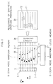
- the transducer array 4 is driven with predetermined time delays to transmit the electronically converged beam 35, and the piezo-electric element 5-1 receives the beam in the range of a broad directional response pattern 37. This operation is repeated twice.
- the signal reflected from the tissues is eliminated so that the component of the signal from the moving target is detected as a deviation signal 38.
- the reason why the signal reflected from the tissues can be eliminated is described below.
- the intensity of the signal reflected from the still tissue becomes zero.
- the intensity of the signal reflected from the blood flow does not become zero since the phase of the signal is shifted in each sequence of beam transmission and reception.
- a kind of MTI filter is realized.
- the result of the operation is stored in the Doppler waveform storage means 31.
- the piezo-electric element 5-2 is selected for receiving the signal reflected from the target.
- the piezo-electric elements for transmitting the beam and the process of transmission are the same as those of sequence 1.
- the subtraction for the signals received by the selected piezo-electric element 5-2 is performed, and its result is stored in the Doppler waveform memory 31.
- the Fourier transformation of the TOF response means synthesizing the ultrasonic beam in the direction of the normal of the TOF locus when the Doppler frequency f d is detected.
- the Doppler information with fine spatial resolution can be detected irrespective of the detection distance.
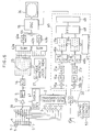
- FIG. 6 an embodiment of an ultrasonic diagnosing apparatus adopting the above-described principles of the present invention will be explained.
- the same elements as those of the apparatus shown in Fig. 11 are given the same reference numerals, and their descriptions are omitted.
- a received signal amplifier 40 is a linear amplifier to amplify the received signal of the selected piezo-electric element.
- the received signal amplifier 40 comprises a gain control amplifier, and changes its gain in accordance with an external control voltage.
- An STC signal generator 41 provides the received signal amplifier 40 with a gain control voltage for compensating the attenuation of the ultrasonic pulse wave traveling in the living body.
- the voltage generated by the STC signal generator 12 shown in Fig. 11 is linearly changed with respect to the depth.
- the voltage generated by the STC signal generator 41 is exponentially changed with respect to the depth. This is because the received signal to be sensitivity-time-controlled has not been logarithmically compressed, but only has been linearly amplified.
- a wavefront locus memory 27 is a look-up table storing a plurality of TOF loci corresponding to the whole space to be observed.
- Summing circuits 42a and 42b sum the real components and imaginary components, respectively, of the received signals read out along the TOF locus.
- Squaring circuits 43a and 43b square the outputs from the summing circuits 42a and 42b, respectively.
- the adder 44 adds the squared amplitudes of the real and imaginary components of the received signal, and outputs the squared amplitude of the received signal.
- a Doppler processing section 45 is provided for detecting the Doppler information by the Fourier transformation of the TOF response as described above.
- a quadrature demodulator 20 and A/D converters 21a and 21b are the same as those in Fig. 11.
- MTI filters 46a and 46b perform subtracting operations for real components I and imaginary components Q, respectively, of the received signals outputted from the quadrature demodulator 20 corresponding to the two transmissions and receptions, and extract the signal component from the moving target.
- Doppler waveform memories 31a and 31b store the real and imaginary components of the moving target signal component, respectively, as time sequential data.
- a Doppler wavefront locus memory 47 is a look-up table for storing the TOF loci of the whole space for which the Doppler information should be detected.
- a fast Fourier transforming circuit 48 Fourier-transforms with respect to the variable x the TOF response read out from the Doppler waveform memories 31a and 31b along the TOF locus.
- a velocity deriving circuit 49 is a circuit to calculate the velocity of the blood flow from the peak frequency of the spatial frequency distribution.
- a timing control circuit 50 generates a master clock with its phase determined by the reference signal generated from a signal generator 1, and outputs to respective electric circuits control signals (not shown) for controlling operations of the whole device in accordance with the master clock (not shown).
- the block diagram for signal processing shown in Fig. 6 is divided into a circuit section for obtaining a B-scan mode image (hereinafter called “ultrasonic tomogram obtaining section”) and the Doppler processing section 45.
- the sequences of the ultrasonic tomogram obtaining section and the Doppler processing section 45 are alternatively performed.
- the multiplexer 39 is changed over under the control of the timing control circuit 50, and an ultrasonic pulse wave is transmitted in a wide range from a selected piezo-element 5-1 by a transmission trigger generating circuit 2 and a transmission signal amplifier 3.
- An ultrasonic wave reflected from a target is received by the selected piezo-electric element 5-1, and amplified with a predetermined gain by the received signal amplifier 40.
- the gain is controlled by the STC signal generator 41 so that the attenuation of the ultrasonic wave in a living body is compensated.
- the signal is converted to a digital signal by an A/D converter 14, which is stored into the B-scan mode waveform memory 26.
- an adjacent piezo-electric element 5-2 is selected by the multiplexer 39.
- the same operations as those for the piezo-electric element 5-1 are performed for the piezo-electric element 5-2 to store the received signal in the B-scan mode waveform memory 26.
- the same process is repeated for the remaining piezo-electric elements 5-3, ..., 5-7.
- the real and imaginary components are separated by a quadrature sampling technique applied when the digital signal is read out from the memory, instead of a conventional quadrature demodulating technique for the analog received signal.
- a quadrature sampling technique two kinds of TOF loci for the real component and the imaginary component are generated from the B-scan mode wavefront locus memory 27. These two kinds of loci are set to read out the received signals at the positions corresponding to the time shift equivalent to a phase shift of ⁇ /2 at the center frequency of the received signals.
- the details are described in Jeffrey E. Powers et al., Ultrasound Phased Array Delay Lines Based on Quadrature Sampling Techniques, IEEE Trans. Sonics and Ultrason., SU-27, 6, pp. 287-294, 1980.
- the real and imaginary components are converted to the power at the focal point by the squaring circuits 43a and 43b and the adder 44, and transmitted to a digital scan converter 15.
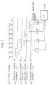
- the transmission trigger generating circuit 2 generates timing signals T1a, T1b, T2a, T2b, ..., which are synchronized with the reference signal generated by the signal generator 1.
- the transmission trigger generating circuit 2 also transmits to the transmission amplifier 3 in synchronism with this timing signal a group of pulse signals with predetermined time delays to focus at a predetermined point.
- the wave reflected from the living body is received by the piezo-electric element 5-1 selected by the multiplexer 39 and converted to an electric signal.
- the signal is amplified by the received signal amplifier 40 and filtered by the band-pass filter 9.
- the real component I and the imaginary component Q are separated by the quadrature demodulator 20 and digitized by the A/D converters 21a and 21b.
- the signal component from the tissue is removed from the received signal by the MTI filters 46a and 46b to obtain only the signal component from the moving target, which is stored in the Doppler waveform memories 31a and 31b.
- the piezo-electric element 5-1 receives the beam twice which corresponds to the two transmission operations of the electronically converged beam at transmission timing T1a and T1b.
- the received signal portions at respective timing are indicated in Fig. 7(b) and their difference is stored in the Doppler waveform memories 47a and 47b.
- the same process is repeated until the signal received by the piezo-electric element 5-4 is stored (See Fig. 7, (c),(d) and (e)).
- the fast Fourier transforming circuit 48 transforms to the spatial spectrum the moving target signals received by the respective piezo-electric elements 5-i and stored in the Doppler waveform memory 31.
- a series of data read out from the Doppler waveform memory 31 is sampled on the bases of the addresses generated by the Doppler wavefront locus memory 47, and it is a kind of spatial signal forming a focal point.
- the blood flow velocities for the whole area in which the Doppler information should be detected are obtained, and transmitted to the digital scan converter 15 as the Doppler information.
- the digital scan converter 15 displays the Doppler information on the color monitor 24 in red colors when the Doppler information is positive (that is, the peak frequency f peak is positive), and in blue colors when the Doppler information is negative (that is, the peak frequency f peak is negative) in such a manner that the Doppler information is superimposed on the ultrasonic tomogram obtained in the ultrasonic tomogram obtaining sequence.
- the MTI filters 46a and 46b adopted in this embodiment will be described further in detail.
- Fig. 8 an example of an MTI filter is shown.
- a first-in first-out (FIFO) memory 51 is a temporary memory for storing the transmitted portion of the received signal.
- a subtracter 52 is provided for subtracting from the output of the FIFO memory 51 the received signal currently being inputted in the MTI filter.
- the operation of the MTI filter is as follows:
- the first received signal is inputted into the FIFO memory 51, and the second received signal is subtracted from the output of the FIFO memory by the subtracter 51.
- the difference between the two received signals obtained by the same piezo-electric element in the two cycles of transmission and reception is calculated to eliminate the signal component reflected from the static tissue.
- each of the MTI filter removes the input signal at a frequency of 1/T.
- the TOF response as the data treated by the fast Fourier transforming circuit 48 is a set of data points sampled substantially at a period of 2T, the number of the data points being N corresponding to the number of the piezo-electric elements 5-i for receiving the ultrasonic wave reflected from the target.
- the maximum frequency f max which can be detected is 1/4T.
- line spectra are positioned at an interval of 1/2NT in this spectrum distribution. The interval between the line spectra equals the minimum frequency f min which can be detected.
- a spectrum of a TOF response is shown.
- the minimum velocity v min of the blood flow is estimated when T is 150 ⁇ s and N is 16.
- the frequency of the used ultrasonic wave is 7.5 MHz and the velocity of the wave in the living body is 1500 m/s
- the wavelength ⁇ of the ultrasonic wave traveling in the living body is 0.2 mm.
- the velocity of the blood flow is obtained within the above range.
- the velocity v d of the blood flow is obtained from the peak frequency f peak of the spectrum.
- the TOF response may not be symmetrical, or the peak of the frequency may not be clear. Consequently, it may be more effective to calculate the velocity v d of the blood flow by utilizing the frequency in which the spread of the spectrum is also considered, such as the center frequency f center representing the center of gravity of the spectrum.
- the center frequency f center representing the center of gravity of the spectrum.
- the clutter component has a small amount of a low frequency AC component.
- the simple MTI filters 46a and 46b cannot completely remove the clutter component. Therefore, it is better to remove the low frequency component from the spectrum of the TOF response.
- the hatched area is the portion of the spectrum affected by the clutter component. Only by removing the data between the positive and negative f c s, the ideal high-pass filter is realized so that the Doppler information is not affected at all by the clutter component. That is, the fast Fourier transforming circuit 48 has the function of filtering in addition to the function of detecting the Doppler frequency.
- the Doppler image may be displayed in the following way.
- the sum of the respective components of the spectrum of the TOF response are summed to be the power of the Doppler component. Then, irrespective of the direction of the blood flow, the Doppler information is converted to the intensity in the red colors in proportion with the power, and displayed. In this display method, all power of the blood reflection signal component is displayed so that the delectability of the blood flow is increased.
- the same piezo-electric element receives the ultrasonic waves twice, and the subtracting operation is performed.
- a large number of transmission and reception sequences may be performed adopting a high order high-pass filter which is a digital filter.
- the Doppler processing section 45 detects the complex amplitude of the received signal by means of the quadrature demodulator 20.
- the complex amplitude of the received signal may be detected based on the quadrature sampling technique adopted in the ultrasonic tomogram obtaining section.
Landscapes
- Physics & Mathematics (AREA)
- Engineering & Computer Science (AREA)
- Radar, Positioning & Navigation (AREA)
- Remote Sensing (AREA)
- Acoustics & Sound (AREA)
- Computer Networks & Wireless Communication (AREA)
- General Physics & Mathematics (AREA)
- Ultra Sonic Daignosis Equipment (AREA)
- Investigating Or Analyzing Materials By The Use Of Ultrasonic Waves (AREA)
- Length Measuring Devices Characterised By Use Of Acoustic Means (AREA)
Applications Claiming Priority (2)
| Application Number | Priority Date | Filing Date | Title |
|---|---|---|---|
| JP265515/95 | 1995-10-13 | ||
| JP7265515A JPH09103431A (ja) | 1995-10-13 | 1995-10-13 | 超音波診断装置 |
Publications (2)
| Publication Number | Publication Date |
|---|---|
| EP0770353A2 true EP0770353A2 (de) | 1997-05-02 |
| EP0770353A3 EP0770353A3 (de) | 1998-12-16 |
Family
ID=17418233
Family Applications (1)
| Application Number | Title | Priority Date | Filing Date |
|---|---|---|---|
| EP96116025A Withdrawn EP0770353A3 (de) | 1995-10-13 | 1996-10-07 | Ultraschalldiagnosegerät |
Country Status (3)
| Country | Link |
|---|---|
| US (1) | US5706818A (de) |
| EP (1) | EP0770353A3 (de) |
| JP (1) | JPH09103431A (de) |
Cited By (1)
| Publication number | Priority date | Publication date | Assignee | Title |
|---|---|---|---|---|
| US6045505A (en) * | 1997-06-17 | 2000-04-04 | Acuson Corporation | Method and apparatus for frequency control of an ultrasound system |
Families Citing this family (24)
| Publication number | Priority date | Publication date | Assignee | Title |
|---|---|---|---|---|
| US5902244A (en) * | 1997-02-05 | 1999-05-11 | Olympus Optical Co., Ltd. | Ultrasonic diagnosis apparatus including simple digital scan converter |
| US7789841B2 (en) | 1997-02-06 | 2010-09-07 | Exogen, Inc. | Method and apparatus for connective tissue treatment |
| US7108663B2 (en) * | 1997-02-06 | 2006-09-19 | Exogen, Inc. | Method and apparatus for cartilage growth stimulation |
| US5904659A (en) | 1997-02-14 | 1999-05-18 | Exogen, Inc. | Ultrasonic treatment for wounds |
| US7211060B1 (en) * | 1998-05-06 | 2007-05-01 | Exogen, Inc. | Ultrasound bandages |
| US6585647B1 (en) | 1998-07-21 | 2003-07-01 | Alan A. Winder | Method and means for synthetic structural imaging and volume estimation of biological tissue organs |
| KR100803810B1 (ko) | 1999-05-21 | 2008-02-14 | 엑조겐 인코포레이티드 | 초음파 및 전자기적으로 조직을 치료하는 장치 |
| EP1408853A1 (de) | 1999-06-14 | 2004-04-21 | Exogen, Inc. | Verfahren und kit durch kavitten ausgelöste gewebeheilung mittels ultraschall niedriger intensität |
| US6685645B1 (en) * | 2001-10-20 | 2004-02-03 | Zonare Medical Systems, Inc. | Broad-beam imaging |
| US6932308B2 (en) * | 2000-10-25 | 2005-08-23 | Exogen, Inc. | Transducer mounting assembly |
| US7429248B1 (en) | 2001-08-09 | 2008-09-30 | Exogen, Inc. | Method and apparatus for controlling acoustic modes in tissue healing applications |
| JP4874497B2 (ja) * | 2001-10-20 | 2012-02-15 | ゾネア メディカル システムズ,インコーポレイテッド | 幅広ビーム映像化 |
| US20030195415A1 (en) * | 2002-02-14 | 2003-10-16 | Iddan Gavriel J. | Device, system and method for accoustic in-vivo measuring |
| US6679847B1 (en) * | 2002-04-30 | 2004-01-20 | Koninklijke Philips Electronics N.V. | Synthetically focused ultrasonic diagnostic imaging system for tissue and flow imaging |
| US7135806B2 (en) * | 2002-10-31 | 2006-11-14 | Hewlett-Packard Development Company, L.P. | Transducer-based sensor system with multiple drive signal variants |
| AU2005205820B2 (en) * | 2004-09-04 | 2011-04-14 | Smith & Nephew Plc | Ultrasound device and method of use |
| DE102005004331B4 (de) * | 2005-01-31 | 2016-05-04 | Robert Bosch Gmbh | Verfahren zur Bestimmung der Laufzeit eines Ultraschallsignals eines Ultraschallsensors sowie Ultraschallsensor |
| JP5446074B2 (ja) * | 2007-06-11 | 2014-03-19 | 株式会社日立製作所 | 血流の計測および評価装置 |
| JP5747429B2 (ja) * | 2007-08-09 | 2015-07-15 | ジーイー・メディカル・システムズ・グローバル・テクノロジー・カンパニー・エルエルシー | 画像処理装置および超音波診断装置 |
| JP5534665B2 (ja) * | 2008-10-21 | 2014-07-02 | キヤノン株式会社 | 超音波診断装置 |
| JP7090609B2 (ja) * | 2016-11-17 | 2022-06-24 | コーニンクレッカ フィリップス エヌ ヴェ | ツインクリングアーチファクトを使用して腎臓結石を検出する超音波システム及び方法 |
| EP3424433A1 (de) | 2017-07-06 | 2019-01-09 | Koninklijke Philips N.V. | Verfahren und systeme zur verarbeitung eines ultraschallbildes |
| JP7387249B2 (ja) * | 2018-01-10 | 2023-11-28 | キヤノンメディカルシステムズ株式会社 | 超音波診断装置、医用画像処理装置及び医用画像処理プログラム |
| JP2025017714A (ja) * | 2023-07-25 | 2025-02-06 | 富士フイルム株式会社 | 超音波診断装置及びプログラム |
Citations (7)
| Publication number | Priority date | Publication date | Assignee | Title |
|---|---|---|---|---|
| US4325257A (en) | 1980-02-20 | 1982-04-20 | Kino Gordon S | Real-time digital, synthetic-focus, acoustic imaging system |
| JPS58188433A (ja) | 1982-04-28 | 1983-11-02 | アロカ株式会社 | 超音波診断装置 |
| JPS6283655A (ja) | 1985-10-09 | 1987-04-17 | Toshiba Corp | 超音波診断装置 |
| JPS62153746A (ja) | 1985-12-27 | 1987-07-08 | Mitsubishi Electric Corp | 超音波もしくは電磁波による物体映像化方法 |
| US4841489A (en) | 1985-12-27 | 1989-06-20 | Mitsubishi Denki Kabushiki Kaisha | Method of imaging an object by ultrasonic or electromagnetic waves |
| US5349960A (en) | 1991-10-01 | 1994-09-27 | Olympus Optical Co., Ltd. | Ultrasonic diagnosis apparatus |
| US5453575A (en) | 1993-02-01 | 1995-09-26 | Endosonics Corporation | Apparatus and method for detecting blood flow in intravascular ultrasonic imaging |
Family Cites Families (4)
| Publication number | Priority date | Publication date | Assignee | Title |
|---|---|---|---|---|
| JPH01110351A (ja) * | 1987-10-23 | 1989-04-27 | Aloka Co Ltd | 超音波ドプラ診断装置 |
| JP3043873B2 (ja) * | 1991-11-29 | 2000-05-22 | フクダ電子株式会社 | 超音波開口面合成装置 |
| US5431169A (en) * | 1992-08-03 | 1995-07-11 | Olympus Optical Co., Ltd. | Ultrasonic diagnosing apparatus |
| US5471990A (en) * | 1994-11-23 | 1995-12-05 | Advanced Technology Laboratories, Inc. | Ultrasonic doppler power measurement and display system |
-
1995
- 1995-10-13 JP JP7265515A patent/JPH09103431A/ja active Pending
-
1996
- 1996-10-04 US US08/726,454 patent/US5706818A/en not_active Expired - Lifetime
- 1996-10-07 EP EP96116025A patent/EP0770353A3/de not_active Withdrawn
Patent Citations (7)
| Publication number | Priority date | Publication date | Assignee | Title |
|---|---|---|---|---|
| US4325257A (en) | 1980-02-20 | 1982-04-20 | Kino Gordon S | Real-time digital, synthetic-focus, acoustic imaging system |
| JPS58188433A (ja) | 1982-04-28 | 1983-11-02 | アロカ株式会社 | 超音波診断装置 |
| JPS6283655A (ja) | 1985-10-09 | 1987-04-17 | Toshiba Corp | 超音波診断装置 |
| JPS62153746A (ja) | 1985-12-27 | 1987-07-08 | Mitsubishi Electric Corp | 超音波もしくは電磁波による物体映像化方法 |
| US4841489A (en) | 1985-12-27 | 1989-06-20 | Mitsubishi Denki Kabushiki Kaisha | Method of imaging an object by ultrasonic or electromagnetic waves |
| US5349960A (en) | 1991-10-01 | 1994-09-27 | Olympus Optical Co., Ltd. | Ultrasonic diagnosis apparatus |
| US5453575A (en) | 1993-02-01 | 1995-09-26 | Endosonics Corporation | Apparatus and method for detecting blood flow in intravascular ultrasonic imaging |
Non-Patent Citations (2)
| Title |
|---|
| JEFFREY E. POWERS ET AL.: "Ultrasound Phased Array Delay Lines Based on Quadrature Sampling", IEEE TRANS. SONUCS AND ULTRASON, SU-27, vol. 27, no. 6, 1980, pages 287 - 294, XP011404338, DOI: doi:10.1109/T-SU.1980.31192 |
| M. OKUSHIMA ET AL.: "Cross Selectional Imaging", MARINE ACOUSTICS - FUNDAMENTALS AND APPLICATIONS, 1984, THE MARINE ACOUSTIC SOCIETY OF JAPAN, pages 171 - 173 |
Cited By (1)
| Publication number | Priority date | Publication date | Assignee | Title |
|---|---|---|---|---|
| US6045505A (en) * | 1997-06-17 | 2000-04-04 | Acuson Corporation | Method and apparatus for frequency control of an ultrasound system |
Also Published As
| Publication number | Publication date |
|---|---|
| US5706818A (en) | 1998-01-13 |
| EP0770353A3 (de) | 1998-12-16 |
| JPH09103431A (ja) | 1997-04-22 |
Similar Documents
| Publication | Publication Date | Title |
|---|---|---|
| US5706818A (en) | Ultrasonic diagnosing apparatus | |
| US6390980B1 (en) | Spatial compounding with ultrasonic doppler signal information | |
| US5349960A (en) | Ultrasonic diagnosis apparatus | |
| USRE35371E (en) | Method and system for controlling ultrasound scanning sequence | |
| US6210332B1 (en) | Method and apparatus for flow imaging using coded excitation | |
| US6312384B1 (en) | Method and apparatus for flow imaging using golay codes | |
| US6139501A (en) | Coincident tissue and motion ultrasonic diagnostic imaging | |
| JP5715594B2 (ja) | フローパラメータイメージングのための方法及び装置 | |
| US5961462A (en) | Ultrasonic doppler imaging at high frame rates of display | |
| US6267725B1 (en) | Individual channel analog wall filtering to improve flow sensitivity in ultrasound imaging | |
| EP1188068B1 (de) | Verfahren und vorrichtung zur blitzunterdrückung in zwei-dimensionaler ultraschall-bilddarstellung | |
| US5938611A (en) | Method and apparatus for color flow imaging using coded excitation with single codes | |
| US5170792A (en) | Adaptive tissue velocity compensation for ultrasonic Doppler imaging | |
| US5349525A (en) | Color flow imaging system utilizing a frequency domain wall filter | |
| EP0947853A2 (de) | Verfahren und Anlage zur verbesserten Ultraschall-B-Bild-Strombilderzeugung | |
| EP0913704A2 (de) | Doppler-Ultraschalldiagnostik-Abbildungssystem mit Pulsumkehr | |
| JPH07303644A (ja) | 超音波診断装置 | |
| JP3093823B2 (ja) | 超音波ドプラ診断装置 | |
| US5327894A (en) | Wall filter using circular convolution for a color flow imaging system | |
| US5891037A (en) | Ultrasonic Doppler imaging system with frequency dependent focus | |
| US5431169A (en) | Ultrasonic diagnosing apparatus | |
| US5406949A (en) | Digital processing for steerable CW doppler | |
| US5476098A (en) | Partially coherent imaging for large-aperture phased arrays | |
| US6544184B1 (en) | Imaging with reduced artifacts for medical diagnostic ultrasound | |
| JPH0614934B2 (ja) | 超音波診断装置 |
Legal Events
| Date | Code | Title | Description |
|---|---|---|---|
| PUAI | Public reference made under article 153(3) epc to a published international application that has entered the european phase |
Free format text: ORIGINAL CODE: 0009012 |
|
| AK | Designated contracting states |
Kind code of ref document: A2 Designated state(s): DE FR GB |
|
| PUAL | Search report despatched |
Free format text: ORIGINAL CODE: 0009013 |
|
| AK | Designated contracting states |
Kind code of ref document: A3 Designated state(s): DE FR GB |
|
| STAA | Information on the status of an ep patent application or granted ep patent |
Free format text: STATUS: THE APPLICATION IS DEEMED TO BE WITHDRAWN |
|
| 18D | Application deemed to be withdrawn |
Effective date: 19990617 |