EP0770408B1 - Stimulateur cardiaque implantable - Google Patents
Stimulateur cardiaque implantable Download PDFInfo
- Publication number
- EP0770408B1 EP0770408B1 EP96307418A EP96307418A EP0770408B1 EP 0770408 B1 EP0770408 B1 EP 0770408B1 EP 96307418 A EP96307418 A EP 96307418A EP 96307418 A EP96307418 A EP 96307418A EP 0770408 B1 EP0770408 B1 EP 0770408B1
- Authority
- EP
- European Patent Office
- Prior art keywords
- pacemaker
- stimulation pulse
- pulse
- cardiac
- evoked
- Prior art date
- Legal status (The legal status is an assumption and is not a legal conclusion. Google has not performed a legal analysis and makes no representation as to the accuracy of the status listed.)
- Expired - Lifetime
Links
Images


Classifications
-
- A—HUMAN NECESSITIES
- A61—MEDICAL OR VETERINARY SCIENCE; HYGIENE
- A61N—ELECTROTHERAPY; MAGNETOTHERAPY; RADIATION THERAPY; ULTRASOUND THERAPY
- A61N1/00—Electrotherapy; Circuits therefor
- A61N1/18—Applying electric currents by contact electrodes
- A61N1/32—Applying electric currents by contact electrodes alternating or intermittent currents
- A61N1/36—Applying electric currents by contact electrodes alternating or intermittent currents for stimulation
- A61N1/362—Heart stimulators
- A61N1/37—Monitoring; Protecting
- A61N1/371—Capture, i.e. successful stimulation
- A61N1/3712—Auto-capture, i.e. automatic adjustment of the stimulation threshold
Definitions
- pacemakers can be programmed to operate in a demand mode of operation, i.e. to generate and deliver stimulation pulses to the heart only when the heart fails to beat on its own.
- the pacemaker senses cardiac activity, i.e., heartbeats, and if the heartbeats do not occur at a prescribed rate, then stimulation pulses are generated by the electronic pacemaker and delivered to an appropriate heart chamber, either the atrium or the ventricle, in order to force the heart to beat.
- the pacemaker When operating in a demand mode of operation, the pacemaker defines a period of time, referred to generally as the "escape interval” (which may further be referred to as either an “atrial escape interval” or a “ventricular escape interval,” depending upon the mode of operation of the pacemaker) that is slightly longer than the period of time between normal or natural heartbeats.
- the escape interval Upon sensing such a “natural,” “sinus” or “spontaneous” (non-stimulated or non-paced) heartbeat within the allotted time period, the escape interval is reset, and a new-escape interval is started.
- a stimulation (or pacing) pulse will be generated at the conclusion of this new escape interval unless a natural heartbeat is again sensed during the escape interval. In this way, stimulation pulses are generated “on demand,” i.e., only when needed in order to maintain the heart rate at a rate that never drops below the rate set by the escape interval.
- the heart rate is monitored by examining the electrical signals that are manifest concurrent with the depolarization or contraction of the myocardial tissue.
- the contraction of atrial muscle tissue is manifest by the generation of a P-wave
- the contraction of ventricular muscle tissue is manifest by the generation of an R-wave (sometimes referred to as the "QRS complex").
- the sequence of electrical signals that represent P-waves, followed by R-waves (or QRS complexes) can be sensed from inside of or directly on the heart by using sensing leads implanted inside or on the heart, e.g., pacemaker leads; or by using external electrodes attached to the skin of the patient.
- This sequence of electrical signals may be represented graphically as an electrographic representation or electrographic signal, and is typically referred to as the electrogram (EGM) when sensed inside or on the heart, and the electrocardiogram (EKG) when sensed using skin electrodes.
- EGM electrogram
- EKG electrocardiogram
- any cardiac activity that is sensed by the electronic pacemaker is presumed to be either noise or residual electrical signals resulting from the prior cardiac contraction, and is therefore ignored by the pacemaker logic circuits.
- the purpose of the AREF or VREF is to prevent the misdetection of spontaneous P-waves or R-waves immediately following the generation of an A-pulse or V-pulse. Any detected cardiac activity during the AREF or VREF should not be used to signal the cardiac pacemaker that .an intrinsic or spontaneous P-wave or R-wave has occurred.
- any response sensed by the atrial sensing circuits of the pacemaker immediately following the application of the A-pulse is assumed to be an evoked atrial response (also referred to as an evoked P-wave) that evidences capture of the atria.
- a period of time referred to as the atrial post-stimulus response detection window or the ventricular post-stimulus response detection window, respectively, is initiated by the pacemaker in response to the generation of an A-pulse or a V-pulse.
- the logic circuitry within the electronic pacemaker associated with the atria or ventricles, respectively, becomes sensitive to the evoked P-wave or the evoked R-wave.
- evoked response refers to P-waves or R-waves that occur during the post-stimulus evoked response detection window.
- spontaneous or intrinsic response refers to P-waves or R-waves that occur after the post-stimulus evoked response detection window.
- the electronic pacemaker By detecting the evoked P-wave or evoked R-wave, the electronic pacemaker is able to detect whether the cardiac stimulation pulse (A-pulse or V-pulse) was effective in capturing the heart, i.e., causing a contraction in the respective chamber of the heart.
- the pacemaker initiates a backup (second) response, which includes generating a backup (second) stimulation pulse some time after the atrial post-stimulus response detection window or ventricular post-stimulus response detection window expires.
- the backup stimulation pulse is typically an A-pulse or V-pulse of greater amplitude, pulse width or both than the initial atrial or ventricular stimulation pulse.
- the backup stimulation pulse is designed to capture the heart when the initial, lower amplitude and/or lower pulse width stimulation pulse was unable to do so.
- Document EP-A-0 598 616 discloses an implantable pacemaker comprising: means for sensing cardiac activity, means for generating a cardiac stimulation pulse, timing means for defining a refractory period during which cardiac activity is not sensed; detecting means for detecting if cardiac activity is evoked by the cardiac stimulation pulse; and means for shortening the refractory period.
- an implantable pacemaker comprising: means for sensing cardiac activity, and means for generating a cardiac stimulation pulse, characterised by: timing means for defining a refractory period during which cardiac activity is not sensed; detecting means for detecting if cardiac activity is evoked by the cardiac stimulation pulse; and terminating means for cutting short the refractory period in the event no cardiac response is evoked by the cardiac stimulation pulse.
- an implantable electronic pacemaker comprising: pulse generator means for generating a first cardiac stimulation pulse; first timing means for initiating an evoked response detection time period, the first timing means being coupled to the pulse generator means; second timing means for initiating a refractory time period in response to the generation of the first cardiac stimulation pulse, the second timing mans being coupled to the pulse generator means; detecting means for detecting whether an evoked response occurs during the evoked response detection time period, the detecting means being coupled to the first timing means, the detecting means detecting whether a spontaneous response occurs following the terminating of the refractory time period; and terminating means for terminating the refractory time period in the event that the detecting means detects that an evoked response did not occur during the evoked a response detection time period, the terminating means being coupled to the detecting means, the second timing means, and the pulse generator means; the pulse generating means generating a second cardiac stimulation pulse in the event the detecting means detects that a spontaneous response did
- an implantable pacemaker so as to enhance it ability to detect a natural cardiac contraction, comprising: means for generating a cardiac stimulation pulse; means for defining a refractory period immediately following the stimulation pulse; means for determining if the issued cardiac stimulation pulse has achieved capture; and means for terminating the refractory period of the pacemaker immediately upon determining that capture was not achieved.
- the present invention advantageously addresses the needs above as well as other needs by providing a system for detecting whether a cardiac response has been evoked by a pacemaker-generated stimulus (A-pulse or V-pulse), or whether spontaneous cardiac activity (natural P-wave or R-wave) has occurred, before a backup electrical stimulation pulse is permitted to be generated by the electronic pacemaker; and for preventing the generation of the backup stimulation pulse in the event evoked or spontaneous cardiac activity is detected.
- a pacemaker-generated stimulus A-pulse or V-pulse
- spontaneous cardiac activity naturally P-wave or R-wave
- the invention can be characterized as a system for preventing the generation of a backup stimulation pulse in the event either evoked cardiac activity or intrinsic (or spontaneous) cardiac activity is detected following the initial stimulation pulse.
- an initial cardiac stimulation pulse is generated, and in response thereto an evoked response detection time period, or window, and a refractory time period (longer than the evoked response detection time period) are simultaneously initiated.
- a determination is next made as to whether an evoked response occurs during the evoked response detection time period.
- the refractory time period is immediately terminated, or cut off, thereby allowing any natural (i.e., intrinsic or spontaneous) cardiac response that occurs thereafter to be detected.
- Such "cutting off" of the refractory time period results in the ending of the refractory time period at a time before a time at which the refractory time period would otherwise end.
- the pacemaker continues to operate in its normal manner. Only when a spontaneous response is not detected following the "cutting off" of the refractory time period is a backup (second) cardiac stimulation pulse permitted to be generated. The backup stimulation pulse is never generated when a spontaneous response is detected following the "cutting off” of the refractory time period.
- the invention can be characterized as an implantable electronic pacemaker.
- the electronic pacemaker employs pulse generator means, first timing means, second timing means, detecting means, and terminating means.
- the pulse generator means generates a first cardiac stimulation pulse at an appropriate time in the cardiac pacing cycle.
- the first timing means initiates an evoked response detection time period in response to the first cardiac stimulation pulse.
- the second timing means likewise initiates a refractory time period in response to the generation of the first cardiac stimulation pulse.
- the detecting means detects whether an evoked response occurs during the evoked response detection time period, and the terminating means immediately terminates the refractory time period as soon as the detecting means detects that an evoked response did not occur during the evoked response detection time period. By terminating the refractory time period in this manner, any natural cardiac activity that occurs thereafter after termination of the refractory time period) can be detected, thereby preserving "correct" information for the continued operation of the pacemaker.
- a backup stimulation pulse used, e.g., in an autocapture mode
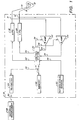
- FIG. 1 a functional block diagram of an exemplary dual-chamber implantable electronic pacemaker 10 is illustrated in accordance with the teachings of one embodiment of the invention.
- the electronic pacemaker 10 is coupled to a heart 12 by way of leads 14, 16, which are coupled to the pacemaker 10 at respective connection points 11, 13.
- the lead 14 has an electrode 15 that is in contact with one of the atria of the heart, and the lead 16 has an electrode 17 that is in contact with one of the ventricles of the heart.
- the leads 14, 16 carry stimulating pulses to the electrodes 15, 17 from either an atrial pulse generator (A-PG) 18 or a ventricular pulse generator (V-PG) 20, respectively, as is known in the art.
- A-PG atrial pulse generator
- V-PG ventricular pulse generator
- the pacemaker 10 is housed in an implantable hermetically sealed housing (not shown), such as are known in the art of implantable electronic pacemakers.
- a control circuit or control system 26 controls the dual-chamber pacemaker 10.
- the control system 26 may be implemented using, e.g., discrete hardware components, a state machine-type design or, preferably, a microprocessor modified with a software routine to carry out the functions described herein.
- An exemplary implementation using a microprocessor-based design is shown in FIGS. 6, 7 and 8, below.
- the microprocessor is modified with a software routine to carry out the steps shown in the flowchart of FIG. 5.
- An exemplary software routine can easily be generated by one skilled in the art to carry out the steps illustrated in FIG. 5.
- An alternative microprocessor-based design is shown in U.S. Patent No. 4,940,053.
- the control system 26 Upon the generation of the stimulation pulse, the control system 26 initiates two time periods: an evoked response detection time period and a refractory time period. Both time periods start simultaneously, but the refractory time period is programmed to last longer than the evoked response detection time period.
- the evoked response detection time period referred to as the atrial evoked response detection window (AERDW) or the ventricular evoked response detection window (VERDW), depending on whether an A-pulse or V-pulse was generated
- the appropriate amplifier 22 or 24 is enabled, and any cardiac activity detected during the AERDW or VERDW is presumed to be an evoked response.
- the blanking signal may be applied to the P-AMP 22 for a period of time following the AERDW, and may be applied to the R-AMP 24 for a period of time following the VERDW.
- the sense amplifiers 22, 24 may remain enabled and the control system 26 may become insensitive to, or ignore, any cardiac activity detected during this portion of the atrial or ventricular refractory period.
- the control system 26 of electronic pacemaker 10 detects whether capture has been achieved by determining whether an evoked P-wave or R-wave has occurred during the AERDW or VERDW, as explained more fully below in reference to FIG. 2. A variation of this capture-determining technique is further explained below in reference to FIG. 4.
- the electronic pacemaker 10 also includes a memory circuit 40 that is coupled to the control system 26 over a suitable data/address bus 42.
- the memory circuit 40 allows certain control parameters, used by the control system 26 in controlling the operation of the electronic pacemaker 10, to be programmably stored and modified, as required, in order to customize the electronic pacemaker's operation to suit the needs of a particular patient.
- Such data includes the basic timing intervals used during operation of the pacemaker, such as an atrial escape interval (AEI), an atrioventricular interval (AVI), the atrial refractory period (AREF), the ventricular refractory period (VREF), the atrial evoked response detection window (AERDW), and the ventricular evoked response detection window (VERDW).
- AEI atrial escape interval
- AVI atrioventricular interval
- AREF atrial refractory period
- VREF ventricular refractory period
- AERDW atrial evoked response detection window
- VERDW ventricular evoked response detection window
- a telemetry circuit 44 is further included in the electronic pacemaker 10.
- This telemetry circuit 44 is connected to the control system 26 by way of a suitable command/data bus 46.
- the telemetry circuit 44 which is included within the implantable electronic pacemaker 10, may be selectively coupled to an external programming device 48 (or external programmer) by means of an appropriate communication link 50.
- the communication link 50 may be any suitable electromagnetic link, such as a radio frequency (RF) communications channel, an inductively-coupled link, an optical link, an infrared link, or the like.
- RF radio frequency
- desired commands and parameters may be sent to the control system 26.
- data may be remotely (i.e., from outside the patient in which the electronic pacemaker 10 is implanted) received from the electronic pacemaker 10.
- data may be remotely (i.e., from outside the patient in which the electronic pacemaker 10 is implanted) received from the electronic pacemaker 10.
- non-invasive communications can be established from time to time with the implanted electronic pacemaker 10 from a remote, non-implanted, location.
- Further details associated with the use of an external programmer that sends and receives data from an implanted pacemaker may be found in, e.g., U.S. Patent No. 4,847,617, issued to Silvian, entitled "High Speed Digital Telemetry System for Implantable Devices,".
- the electronic pacemaker 10 in FIG. 1 is referred to as a dual-chamber pacemaker because it interfaces with both the atria and the ventricles of the heart.
- Those portions of the electronic pacemaker 10 that interface with the atria, e.g., the lead 14, the P-AMP 22, the atrial pulse generator 18, and corresponding portions of the control system 26, are commonly referred to as the atrial channel.
- those portions of the electronic pacemaker 10 that interface with the ventricles, e.g., the lead 16, the R-AMP 24, the ventricular pulse generator 20, and corresponding portions of the control system 26, are commonly referred to as the ventricular channel.
- the electronic pacemaker 10 may further include one or more sensors 52 that is/are connected to the control system 26 over a suitable connection line 54.
- sensors 52 is used to sense some physiological parameter that gives an indication of how fast, or how slowly, the patient's heart should be beating. Such information is then used by the pacemaker to control the pacing rate of the pacemaker so that the heart will be paced at the preferred rate.
- the sensor 52 is illustrated in FIG. 1 as being included within the pacemaker 10, it will be understood by one skilled in the art that the sensor may also be external to the pacemaker 10, yet still be implanted within or carried by the patient.
- a common type of sensor is an activity sensor, such as a piezoelectric crystal, mounted to the case of the electronic pacemaker 10.
- physiologic sensors that sense the oxygen content of blood, respiration rate, pH of blood, and the like, may also be used in lieu of, or in addition to, the activity sensor.
- the type of sensor, if any, used is not critical to the present invention. Any sensor or combination of sensors capable of sensing body motion or a physiological parameter relatable to the rate at which the heart should be beating can be used.
- a pacemaker using such a sensor(s) is commonly referred to as a "rate-responsive" pacemaker because such a pacemaker adjusts the rate (i.e., atrial escape interval (AEI) and atrioventricular interval (AVI)) of the pacemaker in a manner that tracks the physiological needs of the patient.
- AEI atrial escape interval
- AVI atrioventricular interval
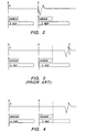
- an exemplary electrographic signal of an evoked P-wave and R-wave is shown in response to the generation of an A-pulse and V-pulse by the implantable electronic pacemaker 10 (FIG. 1). Also shown are the atrial evoked response detection window (AERDW), the atrial refractory period (AREF), the ventricular evoked response detection window (VERDW) and the ventricular refractory period (VREF). As illustrated, the A-pulse (labeled "A" in FIG. 2) is generated by the atrial pulse generator 18, and the evoked P-wave occurs in response thereto. Thus, atrial capture is achieved.
- the atrial evoked response detection window (AERDW) and the atrial refractory period (AREF) are initiated.
- the AERDW typically ranges from 10-20 ms (or even as small as 100 ⁇ s) in duration, e.g., 15 ms, and the AREF typically ranges from 200-400 ms in duration, e.g., 300 ms, thus extending beyond the expiration of the AERDW.
- Any atrial activity sensed by the control system 26 is considered to be an atrial evoked response (evoked P-wave), as shown in FIG. 2.
- the control system 26 is insensitive to cardiac activity. Following the atrial refractory period, the control system 26 is again sensitive to cardiac activity, such as spontaneous atrial contractions, or intrinsic atrial activity.
- a ventricular stimulation pulse (V-pulse) is generated by the ventricular pulse generator 20, and, as shown in FIG. 2, a ventricular evoked response (evoked R-wave) occurs in response thereto.
- evoked R-wave ventricular evoked response
- ventricular capture is achieved.
- the ventricular evoked response detection window (VERDW) and the ventricular refractory period (VREF) are initiated.
- the VERDW typically ranges from 10-50 ms (or even up to 150 ms), and the VREF typically ranges from 200 ms to 300 ms longer than the VERDW.
- the control system 26 is sensitive to ventricular cardiac activity as detected through the lead 16, and specifically to the ventricular evoked response (R-wave) shown in FIG. 2. Following the VERDW, and before the expiration of the VREF, the control system 26 is insensitive to cardiac activity, which activity is assumed to be residual electrical signals resulting from the ventricular stimulation pulse (V-pulse) or from the evoked response (evoked R-wave). Following the ventricular refractory period, the control system 26 is again sensitive to cardiac activity, such as spontaneous ventricular contractions, or intrinsic ventricular activity.
- an exemplary electrographic signal is shown as might occur in response to an implantable electronic pacemaker being operated in a conventional prior art manner.
- an A-pulse is followed by an evoked P-wave, thus evidencing that atrial capture has been achieved.
- the V-pulse does not achieve capture, so no evoked R-wave immediately follows the V-pulse. Instead, the ventricular evoked response detection window expires before any cardiac activity is sensed through the lead 16.
- an exemplary electrographic signal is shown as might occur in response to the implantable pacemaker operating in accordance with one embodiment of the present invention.
- FIG. 4 (as in FIGS. 2 and 3), an A-pulse is followed by an evoked P-wave, thus evidencing that atrial capture has been achieved.
- a V-pulse is generated, which initiates the VERDW and VREF windows.
- the V-pulse does not achieve capture so no evoked R-wave is detected before the expiration of the VERDW.
- backup ventricular support is initiated in accordance with an autocapture mode of operation.
- unlike known implantable electronic pacemaker systems such as those that operate as illustrated in FIG.
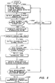
- FIG. 5 a flowchart is shown of the steps traversed by the electronic pacemaker 10 as it carries out one embodiment of the present invention.
- a software routine can be coded by one skilled in the art in order to effectuate the method of FIG. 5 within an off-the-shelf-type microprocessor or a microprocessor within an application specific integrated circuit (ASIC). Such microprocessor or ASIC can in turn be used to implement the control system 26, or equivalent control device.
- the pacemaker starts its programmed operation (Block 1000) the microprocessor is instructed to provide cardiac therapy, including, e.g., P-wave detection, A-pulse generation, and initiation of an AV interval (AVI).
- cardiac therapy including, e.g., P-wave detection, A-pulse generation, and initiation of an AV interval (AVI).
- the microprocessor next detects (1004) whether an intrinsic R-wave occurs following an intrinsic P-wave (or, following an atrial stimulation pulse (A-pulse)) during the AVI. In the event an intrinsic R-wave is detected (Block 1006), an atrial escape interval (AEI) is initiated (Block 1008) and the appropriate cardiac therapy is again initiated (Block 1002). Execution continues (Blocks 1004 et seq.), as described above.
- a ventricular stimulation pulse is generated (Block 1010) and a ventricular evoked response detection window (VERDW) and ventricular refractory period (VREF) are initiated (Block 1012).
- VERDW ventricular evoked response detection window
- VREF ventricular refractory period
- the electronic pacemaker detects (1014) whether an evoked R-wave occurs during the VERDW. Such detection is achieved by sensing whether any ventricular cardiac activity is present during the VERDW. In the event an evoked R-wave is detected during the VERDW (Block 1016) the atrial escape interval is again initiated (Block 1008), and the appropriate therapy is again started (Block 1002) and the process continues (Blocks 1004 et seq.), as described above. In the event, however, an evoked R-wave is not detected during the VERDW (Block 1016), the ventricular refractory period is immediately terminated or cut short (Block 1018).
- the components of the electronic pacemaker 10 are housed within a hermetically sealed case or housing 400 (which case or housing is represented in FIG. 6 by the dashed line 400).
- the case 400 is preferably a titanium metal case.
- the components within the case 400 include an RF coil 402, a memory chip 404, a battery 406, one or more sensors in a sensor circuit 408, a crystal 410, an output/protection network 412, an analog chip 420 and a digital chip 440.
- the battery 406, which is by volume the largest component within the pacemaker 10, may be of conventional design, and is a lithium battery that provides operating power to all of the electronic circuits within the pacemaker.
- the RF coil 402 is used to establish the communication link 50 with the telemetry head 390.
- the crystal 410 is used in conjunction with a crystal oscillator circuit on the digital chip 440 (described below) to provide a stable frequency clock signal. In the preferred embodiment, the frequency of the crystal oscillator is 32 KHz, although any suitable frequency could be used.
- the sensor circuit 408 includes appropriate sensors used by the pacemaker as it carries out rate-responsive pacing functions. For example, in one embodiment, the sensor circuit 408 includes an accelerometer adapted to sense patient activity.
- the analog chip 420 contains the necessary circuitry to sense and detect atrial or ventricular events, digitize IEGM waveforms, measured data and other various analog signals, and provide such sensed and digitized signals to the digital module 434 for use by the digital chip 440.
- the charge pump circuit 438 acts as a voltage doubler/tripler for high output pulse capability.
- the output pulse width is controlled by the output switches 439. The condition of the battery is monitored, and independent Runaway Protection is provided.
- the main control element of the electronic pacemaker 10 is a microprocessor 442, which microprocessor is included within the digital chip 440.
- the microprocessor is modified with a software routine to carry out the steps described in FIG. 5, or in accordance with another desired control method.
- the digital chip 440 contains all the necessary logic to interface the analog chip 420 with the internal microprocessor 442.
- the microprocessor 442 includes a basic central processing unit (CPU) and 8 kilobytes (K) of static RAM.
- an 8 K by 8 K RAM 446 is connected to the microprocessor 442 to store data and programs.
Landscapes
- Health & Medical Sciences (AREA)
- Cardiology (AREA)
- Heart & Thoracic Surgery (AREA)
- Engineering & Computer Science (AREA)
- Biomedical Technology (AREA)
- Nuclear Medicine, Radiotherapy & Molecular Imaging (AREA)
- Radiology & Medical Imaging (AREA)
- Life Sciences & Earth Sciences (AREA)
- Animal Behavior & Ethology (AREA)
- General Health & Medical Sciences (AREA)
- Public Health (AREA)
- Veterinary Medicine (AREA)
- Electrotherapy Devices (AREA)
Claims (11)
- Stimulateur cardiaque implantable comprenant : un moyen pour détecter une activité cardiaque (22, 28, 24, 30), un moyen pour générer une impulsion de stimulation cardiaque (18, 20), un moyen de chronométrage (26) pour définir une période réfractaire pendant laquelle une activité cardiaque n'est pas détectée; un moyen de détection (26) pour détecter si une activité cardiaque est provoquée par l'impulsion de stimulation cardiaque; et un moyen pour mettre fin (26) destiné à interrompre la période réfractaire dans le cas où aucune réponse cardiaque n'est provoquée par l'impulsion de stimulation cardiaque.
- Stimulateur cardiaque selon la revendication 1, caractérisé en ce que le moyen de détection comprend :un moyen pour définir une fenêtre de détection de réponse provoquée qui commence dès que l'impulsion de stimulation cardiaque est générée, et un moyen pour détecter si une réponse cardiaque survient pendant la fenêtre de détection de réponse provoquée.
- Stimulateur cardiaque selon la revendication 2, caractérisé en ce que le moyen pour mettre fin comprend un moyen pour terminer la période réfractaire coïncidant avec l'expiration de la fenêtre de détection de réponse provoquée.
- Stimulateur cardiaque électronique implantable comprenant : un moyen générateur d'impulsion (18, 20) pour générer une première impulsion de stimulation cardiaque; un premier moyen de chronométrage (26) pour initier un intervalle de temps de détection de réponse provoquée, le premier moyen de chronométrage (26) étant couplé au moyen générateur d'impulsion (18, 20); un second moyen de chronométrage (26) pour initier une période réfractaire en réponse à la génération de la première impulsion de stimulation cardiaque, le second moyen de chronométrage (26) étant couplé au moyen générateur d'impulsion (18, 20); un moyen de détection (22, 28, 24, 30) pour détecter si une réponse provoquée survient pendant le délai de détection de réponse provoquée, le moyen de détection étant couplé au premier moyen de chronométrage (26), le moyen de détection détectant si une réponse spontanée survient suite à la fin de la période réfractaire; et un moyen pour mettre fin (26) destiné à mettre fin à la période réfractaire dans le cas où le moyen de détection détecte qu'une réponse provoquée n'est pas survenue pendant le délai de détection de réponse provoquée, le moyen pour mettre fin (26) étant couplé au moyen de détection, au second moyen de chronométrage et au moyen générateur d'impulsion; le moyen générateur d'impulsion (18, 20) générant une seconde impulsion de stimulation cardiaque dans le cas où le moyen de détection détecte qu'une réponse spontanée n'est pas survenue faisant suite à la fin de la période réfractaire.
- Stimulateur cardiaque selon la revendication 4, caractérisé en ce que le délai de détection de réponse provoquée est d'au moins 100 microsecondes et pas plus de 150 millisecondes, et est de préférence de moins de vingt millisecondes.
- Stimulateur cardiaque selon la revendication 4 ou la revendication 5, caractérisé en ce que la première impulsion de stimulation cardiaque comprend une impulsion de stimulation ventriculaire et/ou une impulsion de stimulation auriculaire.
- Stimulateur cardiaque selon une quelconque des revendications 4 à 6, caractérisé en ce que le moyen pour mettre fin est disposé pour mettre fin à la période réfractaire simultanément avec l'expiration du délai de détection de réponse provoquée.
- Stimulateur cardiaque selon une quelconque des revendications 4 à 7, caractérisé en ce que le moyen de détection est disposé pour déterminer si la réponse provoquée pendant le délai de détection de réponse provoquée survient avant la fin du délai de détection de réponse provoquée.
- Stimulateur cardiaque selon une quelconque des revendications 4 à 8, caractérisé en ce que la seconde impulsion de stimulation cardiaque est d'énergie plus grande que la première impulsion de stimulation cardiaque et/ou est de largeur d'impulsion plus grande que la première impulsion de stimulation cardiaque.
- Stimulateur cardiaque implantable destiné à améliorer sa capacité à détecter une contraction cardiaque naturelle, comprenant : un moyen pour générer une impulsion de stimulation cardiaque (18,20); un moyen pour définir une période réfractaire (26) suivant immédiatement l'impulsion de stimulation; un moyen pour déterminer si l'impulsion de stimulation cardiaque émise a réussi une capture (26); et un moyen pour mettre fin à la période réfractaire (26) du stimulateur cardiaque immédiatement après avoir déterminé que la capture n'a pas été réussie.
- Stimulateur cardiaque selon la revendication 10, caractérisé en ce que l'impulsion de stimulation cardiaque est une impulsion de stimulation ventriculaire et la période réfractaire pour mettre fin est une période réfractaire ventriculaire, ou l'impulsion de stimulation cardiaque est une impulsion de stimulation auriculaire et la période réfractaire pour mettre fin est une période réfractaire auriculaire.
Applications Claiming Priority (2)
| Application Number | Priority Date | Filing Date | Title |
|---|---|---|---|
| US08/542,088 US5713934A (en) | 1995-10-12 | 1995-10-12 | Evoked and spontaneous cardiac activity detection in a dual-chamber electronic pacemaker and method |
| US542088 | 1995-10-12 |
Publications (3)
| Publication Number | Publication Date |
|---|---|
| EP0770408A2 EP0770408A2 (fr) | 1997-05-02 |
| EP0770408A3 EP0770408A3 (fr) | 1998-10-14 |
| EP0770408B1 true EP0770408B1 (fr) | 2004-03-03 |
Family
ID=24162287
Family Applications (1)
| Application Number | Title | Priority Date | Filing Date |
|---|---|---|---|
| EP96307418A Expired - Lifetime EP0770408B1 (fr) | 1995-10-12 | 1996-10-11 | Stimulateur cardiaque implantable |
Country Status (4)
| Country | Link |
|---|---|
| US (1) | US5713934A (fr) |
| EP (1) | EP0770408B1 (fr) |
| JP (1) | JPH09122251A (fr) |
| DE (1) | DE69631727T2 (fr) |
Cited By (3)
| Publication number | Priority date | Publication date | Assignee | Title |
|---|---|---|---|---|
| US7308310B1 (en) | 2005-01-26 | 2007-12-11 | Pacesetter, Inc. | Implantable cardiac stimulation device providing bipolar autocapture and lead impedance assessment and method |
| US7574259B1 (en) | 2004-11-12 | 2009-08-11 | Pacesetter, Inc. | Capture threshold and lead condition analysis |
| WO2011069535A1 (fr) * | 2009-12-08 | 2011-06-16 | St. Jude Medical Ab | Dispositif de stimulation cardiaque avec une impulsion de secours |
Families Citing this family (13)
| Publication number | Priority date | Publication date | Assignee | Title |
|---|---|---|---|---|
| US6128532A (en) * | 1998-09-15 | 2000-10-03 | Vitatron Medical, B.V. | Pacemaker with automatically controlled ventricular safety pulse |
| US6418343B1 (en) * | 1999-10-01 | 2002-07-09 | Cardiac Pacemakers, Inc. | Method and apparatus for adjusting the sensing threshold of a cardiac rhythm management device |
| SE9904227D0 (sv) | 1999-11-22 | 1999-11-22 | Pacesetter Ab | A cardiac stimulating device |
| US6553259B2 (en) * | 2001-03-14 | 2003-04-22 | Pacesetter, Inc. | System and method of performing automatic capture in an implantable cardiac stimulation device |
| US7340303B2 (en) * | 2001-09-25 | 2008-03-04 | Cardiac Pacemakers, Inc. | Evoked response sensing for ischemia detection |
| US6768924B2 (en) | 2002-01-03 | 2004-07-27 | Cardiac Pacemakers, Inc. | Method and apparatus for capture verification based on propagated electrical activity |
| US7349738B1 (en) | 2003-02-19 | 2008-03-25 | Pacesetter, Inc. | Detecting atrial evoked response |
| US6928326B1 (en) | 2003-03-31 | 2005-08-09 | Pacesetter, Inc. | Diagnosis of fusion or pseudofusion |
| US6973350B1 (en) | 2003-03-31 | 2005-12-06 | Pacesetter, Inc. | Diagnosis of atrial fusion, atrial pseudofusion and/or native atrial activity |
| US7320675B2 (en) * | 2003-08-21 | 2008-01-22 | Cardiac Pacemakers, Inc. | Method and apparatus for modulating cellular metabolism during post-ischemia or heart failure |
| JP5061011B2 (ja) * | 2008-03-31 | 2012-10-31 | フクダ電子株式会社 | ペースメーカパルス検出装置 |
| US10722724B2 (en) | 2017-05-25 | 2020-07-28 | Pacesetter, Inc. | Always on receiver with offset correction for implant to implant communication in an implantable medical system |
| EP4294506B1 (fr) * | 2021-02-17 | 2025-09-10 | BIOTRONIK SE & Co. KG | Dispositif médical implantable conçu pour fournir une fonction intracardiaque |
Family Cites Families (13)
| Publication number | Priority date | Publication date | Assignee | Title |
|---|---|---|---|---|
| US4817605A (en) * | 1984-10-19 | 1989-04-04 | Siemens-Pacesetter, Inc. | Pacemaker system and method for measuring and monitoring cardiac activity and for determining and maintaining capture |
| US4686988A (en) * | 1984-10-19 | 1987-08-18 | Sholder Jason A | Pacemaker system and method for measuring and monitoring cardiac activity and for determining and maintaining capture |
| US4847617A (en) * | 1987-08-14 | 1989-07-11 | Siemens-Pacesetter, Inc. | High speed digital telemetry system for implantable devices |
| US4815469A (en) * | 1987-10-08 | 1989-03-28 | Siemens-Pacesetter, Inc. | Implantable blood oxygen sensor and method of use |
| US4809697A (en) * | 1987-10-14 | 1989-03-07 | Siemens-Pacesetter, Inc. | Interactive programming and diagnostic system for use with implantable pacemaker |
| US4969467A (en) * | 1988-03-25 | 1990-11-13 | Telectronics N.V. | Pacemaker with improved automatic output regulation |
| US4940052A (en) * | 1989-01-25 | 1990-07-10 | Siemens-Pacesetter, Inc. | Microprocessor controlled rate-responsive pacemaker having automatic rate response threshold adjustment |
| US4940053A (en) * | 1989-01-25 | 1990-07-10 | Siemens-Pacesetter, Inc. | Energy controlled rate-responsive pacemaker having automatically adjustable control parameters |
| US5222493A (en) * | 1990-10-01 | 1993-06-29 | Siemens Pacesetter, Inc. | Verification of capture using an indifferent electrode mounted on the pacemaker connector top |
| US5301669A (en) * | 1991-08-05 | 1994-04-12 | Siemens Pacesetter, Inc. | System and method for preventing atrial competition during sensor-driven operation of a dual-chamber pacemaker |
| EP0578793B1 (fr) * | 1992-02-03 | 1996-11-20 | Medtronic, Inc. | Systeme de stimulateur cardiaque a chambre double utilise pour fournir des impulsions auriculaires synchrones |
| US5247929A (en) * | 1992-02-04 | 1993-09-28 | Vitatron Medical, B.V. | Dual chamber pacemaker with AV extension and PMT control |
| US5443485A (en) * | 1993-09-08 | 1995-08-22 | Intermedics, Inc. | Apparatus and method for capture detection in a cardiac stimulator |
-
1995
- 1995-10-12 US US08/542,088 patent/US5713934A/en not_active Expired - Lifetime
-
1996
- 1996-10-09 JP JP8285847A patent/JPH09122251A/ja active Pending
- 1996-10-11 DE DE69631727T patent/DE69631727T2/de not_active Expired - Lifetime
- 1996-10-11 EP EP96307418A patent/EP0770408B1/fr not_active Expired - Lifetime
Cited By (9)
| Publication number | Priority date | Publication date | Assignee | Title |
|---|---|---|---|---|
| US7574259B1 (en) | 2004-11-12 | 2009-08-11 | Pacesetter, Inc. | Capture threshold and lead condition analysis |
| US8498706B2 (en) | 2004-11-12 | 2013-07-30 | Pacesetter, Inc. | Capture threshold and lead condition analysis |
| US9008774B2 (en) | 2004-11-12 | 2015-04-14 | Pacesetter, Inc. | Capture threshold and lead condition analysis |
| US9238136B2 (en) | 2004-11-12 | 2016-01-19 | Pacesetter, Inc. | Capture threshold and lead condition analysis |
| US9511221B2 (en) | 2004-11-12 | 2016-12-06 | Pacesetter, Inc. | Capture threshold and lead condition analysis |
| US7308310B1 (en) | 2005-01-26 | 2007-12-11 | Pacesetter, Inc. | Implantable cardiac stimulation device providing bipolar autocapture and lead impedance assessment and method |
| WO2011069535A1 (fr) * | 2009-12-08 | 2011-06-16 | St. Jude Medical Ab | Dispositif de stimulation cardiaque avec une impulsion de secours |
| US8700153B2 (en) | 2009-12-08 | 2014-04-15 | St. Jude Medical Ab | Cardiac stimulating device |
| US9283395B2 (en) | 2009-12-08 | 2016-03-15 | St. Jude Medical Ab | Cardiac stimulating device |
Also Published As
| Publication number | Publication date |
|---|---|
| DE69631727T2 (de) | 2004-08-05 |
| US5713934A (en) | 1998-02-03 |
| DE69631727D1 (de) | 2004-04-08 |
| EP0770408A2 (fr) | 1997-05-02 |
| EP0770408A3 (fr) | 1998-10-14 |
| JPH09122251A (ja) | 1997-05-13 |
Similar Documents
| Publication | Publication Date | Title |
|---|---|---|
| US5476487A (en) | Autothreshold assessment in an implantable pacemaker | |
| US5788717A (en) | Atrial rate determination and atrial tachycardia detection in a dual-chamber implantable pacemaker | |
| EP0760697B1 (fr) | Stimulation bi-cavite a independance auriculo-ventriculaire | |
| US8180450B2 (en) | Multi-chamber ventricular automatic capture method and apparatus for minimizing true and blanking period induced ventricular undersensing | |
| US5336244A (en) | Temperature sensor based capture detection for a pacer | |
| US5814077A (en) | Pacemaker and method of operating same that provides functional atrial cardiac pacing with ventricular support | |
| US8583235B2 (en) | Cardiac rhythm management system and method | |
| EP0872260B1 (fr) | Stimulateur cardiaque implantable | |
| EP1317307B1 (fr) | Systeme pour generateur d'impulsions | |
| US5342405A (en) | System and method for selecting a mode of operation of a dual-chamber pacemaker | |
| EP2490758B1 (fr) | Amélioration pour une stimulation ventriculaire minimale afin de rompre le diagramme ar-vs répétitif | |
| US5713934A (en) | Evoked and spontaneous cardiac activity detection in a dual-chamber electronic pacemaker and method | |
| EP0526798A1 (fr) | Stimulateur cardiaque bicavitaire à la demande | |
| EP1339454B1 (fr) | Distinction entre detections cardiaques valides et invalides | |
| US7424323B1 (en) | Implantable cardiac stimulation device providing autocapture with PMT avoidance and method | |
| AU661446B2 (en) | System and method for preventing atrial competition during sensor-driven operation of a dual-chamber pacemaker | |
| EP1078651B1 (fr) | Stimulateur cardiaque implantable et méthode pour détecter une tachycardie induite par un stimulateur |
Legal Events
| Date | Code | Title | Description |
|---|---|---|---|
| PUAI | Public reference made under article 153(3) epc to a published international application that has entered the european phase |
Free format text: ORIGINAL CODE: 0009012 |
|
| AK | Designated contracting states |
Kind code of ref document: A2 Designated state(s): DE ES FR GB IT NL |
|
| PUAL | Search report despatched |
Free format text: ORIGINAL CODE: 0009013 |
|
| AK | Designated contracting states |
Kind code of ref document: A3 Designated state(s): DE ES FR GB IT NL |
|
| 17P | Request for examination filed |
Effective date: 19981109 |
|
| GRAP | Despatch of communication of intention to grant a patent |
Free format text: ORIGINAL CODE: EPIDOSNIGR1 |
|
| GRAS | Grant fee paid |
Free format text: ORIGINAL CODE: EPIDOSNIGR3 |
|
| GRAA | (expected) grant |
Free format text: ORIGINAL CODE: 0009210 |
|
| AK | Designated contracting states |
Kind code of ref document: B1 Designated state(s): DE ES FR GB IT NL |
|
| PG25 | Lapsed in a contracting state [announced via postgrant information from national office to epo] |
Ref country code: NL Free format text: LAPSE BECAUSE OF FAILURE TO SUBMIT A TRANSLATION OF THE DESCRIPTION OR TO PAY THE FEE WITHIN THE PRESCRIBED TIME-LIMIT Effective date: 20040303 |
|
| REG | Reference to a national code |
Ref country code: GB Ref legal event code: FG4D |
|
| REF | Corresponds to: |
Ref document number: 69631727 Country of ref document: DE Date of ref document: 20040408 Kind code of ref document: P |
|
| PG25 | Lapsed in a contracting state [announced via postgrant information from national office to epo] |
Ref country code: ES Free format text: LAPSE BECAUSE OF FAILURE TO SUBMIT A TRANSLATION OF THE DESCRIPTION OR TO PAY THE FEE WITHIN THE PRESCRIBED TIME-LIMIT Effective date: 20040614 |
|
| NLV1 | Nl: lapsed or annulled due to failure to fulfill the requirements of art. 29p and 29m of the patents act | ||
| PG25 | Lapsed in a contracting state [announced via postgrant information from national office to epo] |
Ref country code: GB Free format text: LAPSE BECAUSE OF NON-PAYMENT OF DUE FEES Effective date: 20041011 |
|
| ET | Fr: translation filed | ||
| PLBE | No opposition filed within time limit |
Free format text: ORIGINAL CODE: 0009261 |
|
| STAA | Information on the status of an ep patent application or granted ep patent |
Free format text: STATUS: NO OPPOSITION FILED WITHIN TIME LIMIT |
|
| 26N | No opposition filed |
Effective date: 20041206 |
|
| GBPC | Gb: european patent ceased through non-payment of renewal fee |
Effective date: 20041011 |
|
| PGFP | Annual fee paid to national office [announced via postgrant information from national office to epo] |
Ref country code: IT Payment date: 20101028 Year of fee payment: 15 |
|
| PGFP | Annual fee paid to national office [announced via postgrant information from national office to epo] |
Ref country code: FR Payment date: 20111028 Year of fee payment: 16 |
|
| REG | Reference to a national code |
Ref country code: FR Ref legal event code: ST Effective date: 20130628 |
|
| PG25 | Lapsed in a contracting state [announced via postgrant information from national office to epo] |
Ref country code: IT Free format text: LAPSE BECAUSE OF NON-PAYMENT OF DUE FEES Effective date: 20121011 Ref country code: FR Free format text: LAPSE BECAUSE OF NON-PAYMENT OF DUE FEES Effective date: 20121031 |
|
| PGFP | Annual fee paid to national office [announced via postgrant information from national office to epo] |
Ref country code: DE Payment date: 20141128 Year of fee payment: 19 |
|
| REG | Reference to a national code |
Ref country code: DE Ref legal event code: R119 Ref document number: 69631727 Country of ref document: DE |
|
| PG25 | Lapsed in a contracting state [announced via postgrant information from national office to epo] |
Ref country code: DE Free format text: LAPSE BECAUSE OF NON-PAYMENT OF DUE FEES Effective date: 20160503 |