EP0770800B1 - Une transmission automatique - Google Patents
Une transmission automatique Download PDFInfo
- Publication number
- EP0770800B1 EP0770800B1 EP96307762A EP96307762A EP0770800B1 EP 0770800 B1 EP0770800 B1 EP 0770800B1 EP 96307762 A EP96307762 A EP 96307762A EP 96307762 A EP96307762 A EP 96307762A EP 0770800 B1 EP0770800 B1 EP 0770800B1
- Authority
- EP
- European Patent Office
- Prior art keywords
- gear unit
- speed
- pressure
- control
- brake
- Prior art date
- Legal status (The legal status is an assumption and is not a legal conclusion. Google has not performed a legal analysis and makes no representation as to the accuracy of the status listed.)
- Expired - Lifetime
Links
- 230000005540 biological transmission Effects 0.000 title claims description 109
- 238000006243 chemical reaction Methods 0.000 claims description 62
- 230000000694 effects Effects 0.000 claims description 14
- 230000008878 coupling Effects 0.000 claims description 4
- 238000010168 coupling process Methods 0.000 claims description 4
- 238000005859 coupling reaction Methods 0.000 claims description 4
- 230000007704 transition Effects 0.000 claims description 2
- 238000004873 anchoring Methods 0.000 claims 2
- 230000001276 controlling effect Effects 0.000 claims 2
- 230000001105 regulatory effect Effects 0.000 claims 1
- 238000011217 control strategy Methods 0.000 description 37
- 230000001360 synchronised effect Effects 0.000 description 16
- 238000004364 calculation method Methods 0.000 description 9
- 230000008859 change Effects 0.000 description 9
- 230000007423 decrease Effects 0.000 description 5
- 230000001419 dependent effect Effects 0.000 description 5
- 238000012795 verification Methods 0.000 description 5
- 239000008186 active pharmaceutical agent Substances 0.000 description 4
- 230000003247 decreasing effect Effects 0.000 description 4
- 238000010586 diagram Methods 0.000 description 4
- 238000000034 method Methods 0.000 description 4
- QHLFJSMAWAWVRU-UHFFFAOYSA-N n-(5-chloro-4-methyl-1,3-thiazol-2-yl)propanamide Chemical compound CCC(=O)NC1=NC(C)=C(Cl)S1 QHLFJSMAWAWVRU-UHFFFAOYSA-N 0.000 description 4
- 230000002441 reversible effect Effects 0.000 description 4
- 101100168642 Arabidopsis thaliana CRN gene Proteins 0.000 description 3
- 101100045632 Arabidopsis thaliana TCX2 gene Proteins 0.000 description 3
- 230000009471 action Effects 0.000 description 3
- 230000000977 initiatory effect Effects 0.000 description 3
- 238000012544 monitoring process Methods 0.000 description 3
- 101150103732 sol2 gene Proteins 0.000 description 3
- 238000012546 transfer Methods 0.000 description 3
- 101100045633 Arabidopsis thaliana TCX3 gene Proteins 0.000 description 2
- 101150037491 SOL1 gene Proteins 0.000 description 2
- 238000009825 accumulation Methods 0.000 description 2
- 230000036039 immunity Effects 0.000 description 2
- 239000011159 matrix material Substances 0.000 description 2
- 230000007935 neutral effect Effects 0.000 description 2
- 230000008569 process Effects 0.000 description 2
- 230000004044 response Effects 0.000 description 2
- 230000001960 triggered effect Effects 0.000 description 2
- 101001059713 Homo sapiens Inner nuclear membrane protein Man1 Proteins 0.000 description 1
- 102100028799 Inner nuclear membrane protein Man1 Human genes 0.000 description 1
- 101150076564 MAN2 gene Proteins 0.000 description 1
- 230000001133 acceleration Effects 0.000 description 1
- 238000013459 approach Methods 0.000 description 1
- 230000008901 benefit Effects 0.000 description 1
- 238000002485 combustion reaction Methods 0.000 description 1
- 150000001875 compounds Chemical class 0.000 description 1
- 230000001143 conditioned effect Effects 0.000 description 1
- 238000010276 construction Methods 0.000 description 1
- 239000012530 fluid Substances 0.000 description 1
- 239000000446 fuel Substances 0.000 description 1
- 230000003993 interaction Effects 0.000 description 1
- 230000002452 interceptive effect Effects 0.000 description 1
Images






Classifications
-
- F—MECHANICAL ENGINEERING; LIGHTING; HEATING; WEAPONS; BLASTING
- F16—ENGINEERING ELEMENTS AND UNITS; GENERAL MEASURES FOR PRODUCING AND MAINTAINING EFFECTIVE FUNCTIONING OF MACHINES OR INSTALLATIONS; THERMAL INSULATION IN GENERAL
- F16H—GEARING
- F16H61/00—Control functions within control units of change-speed- or reversing-gearings for conveying rotary motion ; Control of exclusively fluid gearing, friction gearing, gearings with endless flexible members or other particular types of gearing
- F16H61/70—Control functions within control units of change-speed- or reversing-gearings for conveying rotary motion ; Control of exclusively fluid gearing, friction gearing, gearings with endless flexible members or other particular types of gearing specially adapted for change-speed gearing in group arrangement, i.e. with separate change-speed gear trains arranged in series, e.g. range or overdrive-type gearing arrangements
- F16H61/702—Control functions within control units of change-speed- or reversing-gearings for conveying rotary motion ; Control of exclusively fluid gearing, friction gearing, gearings with endless flexible members or other particular types of gearing specially adapted for change-speed gearing in group arrangement, i.e. with separate change-speed gear trains arranged in series, e.g. range or overdrive-type gearing arrangements using electric or electrohydraulic control means
-
- F—MECHANICAL ENGINEERING; LIGHTING; HEATING; WEAPONS; BLASTING
- F16—ENGINEERING ELEMENTS AND UNITS; GENERAL MEASURES FOR PRODUCING AND MAINTAINING EFFECTIVE FUNCTIONING OF MACHINES OR INSTALLATIONS; THERMAL INSULATION IN GENERAL
- F16H—GEARING
- F16H61/00—Control functions within control units of change-speed- or reversing-gearings for conveying rotary motion ; Control of exclusively fluid gearing, friction gearing, gearings with endless flexible members or other particular types of gearing
- F16H61/04—Smoothing ratio shift
- F16H61/06—Smoothing ratio shift by controlling rate of change of fluid pressure
- F16H61/061—Smoothing ratio shift by controlling rate of change of fluid pressure using electric control means
-
- F—MECHANICAL ENGINEERING; LIGHTING; HEATING; WEAPONS; BLASTING
- F16—ENGINEERING ELEMENTS AND UNITS; GENERAL MEASURES FOR PRODUCING AND MAINTAINING EFFECTIVE FUNCTIONING OF MACHINES OR INSTALLATIONS; THERMAL INSULATION IN GENERAL
- F16H—GEARING
- F16H59/00—Control inputs to control units of change-speed- or reversing-gearings for conveying rotary motion
- F16H59/36—Inputs being a function of speed
- F16H59/38—Inputs being a function of speed of gearing elements
- F16H2059/385—Turbine speed
-
- F—MECHANICAL ENGINEERING; LIGHTING; HEATING; WEAPONS; BLASTING
- F16—ENGINEERING ELEMENTS AND UNITS; GENERAL MEASURES FOR PRODUCING AND MAINTAINING EFFECTIVE FUNCTIONING OF MACHINES OR INSTALLATIONS; THERMAL INSULATION IN GENERAL
- F16H—GEARING
- F16H61/00—Control functions within control units of change-speed- or reversing-gearings for conveying rotary motion ; Control of exclusively fluid gearing, friction gearing, gearings with endless flexible members or other particular types of gearing
- F16H2061/0075—Control functions within control units of change-speed- or reversing-gearings for conveying rotary motion ; Control of exclusively fluid gearing, friction gearing, gearings with endless flexible members or other particular types of gearing characterised by a particular control method
- F16H2061/0078—Linear control, e.g. PID, state feedback or Kalman
-
- F—MECHANICAL ENGINEERING; LIGHTING; HEATING; WEAPONS; BLASTING
- F16—ENGINEERING ELEMENTS AND UNITS; GENERAL MEASURES FOR PRODUCING AND MAINTAINING EFFECTIVE FUNCTIONING OF MACHINES OR INSTALLATIONS; THERMAL INSULATION IN GENERAL
- F16H—GEARING
- F16H61/00—Control functions within control units of change-speed- or reversing-gearings for conveying rotary motion ; Control of exclusively fluid gearing, friction gearing, gearings with endless flexible members or other particular types of gearing
- F16H61/02—Control functions within control units of change-speed- or reversing-gearings for conveying rotary motion ; Control of exclusively fluid gearing, friction gearing, gearings with endless flexible members or other particular types of gearing characterised by the signals used
- F16H61/0202—Control functions within control units of change-speed- or reversing-gearings for conveying rotary motion ; Control of exclusively fluid gearing, friction gearing, gearings with endless flexible members or other particular types of gearing characterised by the signals used the signals being electric
- F16H61/0204—Control functions within control units of change-speed- or reversing-gearings for conveying rotary motion ; Control of exclusively fluid gearing, friction gearing, gearings with endless flexible members or other particular types of gearing characterised by the signals used the signals being electric for gearshift control, e.g. control functions for performing shifting or generation of shift signal
- F16H61/0206—Layout of electro-hydraulic control circuits, e.g. arrangement of valves
- F16H2061/0209—Layout of electro-hydraulic control circuits, e.g. arrangement of valves with independent solenoid valves modulating the pressure individually for each clutch or brake
-
- F—MECHANICAL ENGINEERING; LIGHTING; HEATING; WEAPONS; BLASTING
- F16—ENGINEERING ELEMENTS AND UNITS; GENERAL MEASURES FOR PRODUCING AND MAINTAINING EFFECTIVE FUNCTIONING OF MACHINES OR INSTALLATIONS; THERMAL INSULATION IN GENERAL
- F16H—GEARING
- F16H61/00—Control functions within control units of change-speed- or reversing-gearings for conveying rotary motion ; Control of exclusively fluid gearing, friction gearing, gearings with endless flexible members or other particular types of gearing
- F16H61/02—Control functions within control units of change-speed- or reversing-gearings for conveying rotary motion ; Control of exclusively fluid gearing, friction gearing, gearings with endless flexible members or other particular types of gearing characterised by the signals used
- F16H61/0202—Control functions within control units of change-speed- or reversing-gearings for conveying rotary motion ; Control of exclusively fluid gearing, friction gearing, gearings with endless flexible members or other particular types of gearing characterised by the signals used the signals being electric
- F16H61/0251—Elements specially adapted for electric control units, e.g. valves for converting electrical signals to fluid signals
- F16H2061/0255—Solenoid valve using PWM or duty-cycle control
-
- F—MECHANICAL ENGINEERING; LIGHTING; HEATING; WEAPONS; BLASTING
- F16—ENGINEERING ELEMENTS AND UNITS; GENERAL MEASURES FOR PRODUCING AND MAINTAINING EFFECTIVE FUNCTIONING OF MACHINES OR INSTALLATIONS; THERMAL INSULATION IN GENERAL
- F16H—GEARING
- F16H61/00—Control functions within control units of change-speed- or reversing-gearings for conveying rotary motion ; Control of exclusively fluid gearing, friction gearing, gearings with endless flexible members or other particular types of gearing
- F16H61/02—Control functions within control units of change-speed- or reversing-gearings for conveying rotary motion ; Control of exclusively fluid gearing, friction gearing, gearings with endless flexible members or other particular types of gearing characterised by the signals used
- F16H61/0202—Control functions within control units of change-speed- or reversing-gearings for conveying rotary motion ; Control of exclusively fluid gearing, friction gearing, gearings with endless flexible members or other particular types of gearing characterised by the signals used the signals being electric
- F16H61/0251—Elements specially adapted for electric control units, e.g. valves for converting electrical signals to fluid signals
- F16H2061/0258—Proportional solenoid valve
-
- F—MECHANICAL ENGINEERING; LIGHTING; HEATING; WEAPONS; BLASTING
- F16—ENGINEERING ELEMENTS AND UNITS; GENERAL MEASURES FOR PRODUCING AND MAINTAINING EFFECTIVE FUNCTIONING OF MACHINES OR INSTALLATIONS; THERMAL INSULATION IN GENERAL
- F16H—GEARING
- F16H61/00—Control functions within control units of change-speed- or reversing-gearings for conveying rotary motion ; Control of exclusively fluid gearing, friction gearing, gearings with endless flexible members or other particular types of gearing
- F16H61/04—Smoothing ratio shift
- F16H2061/0451—Smoothing ratio shift during swap-shifts, i.e. gear shifts between different planetary units, e.g. with double transitions shift involving three or more friction members
-
- F—MECHANICAL ENGINEERING; LIGHTING; HEATING; WEAPONS; BLASTING
- F16—ENGINEERING ELEMENTS AND UNITS; GENERAL MEASURES FOR PRODUCING AND MAINTAINING EFFECTIVE FUNCTIONING OF MACHINES OR INSTALLATIONS; THERMAL INSULATION IN GENERAL
- F16H—GEARING
- F16H61/00—Control functions within control units of change-speed- or reversing-gearings for conveying rotary motion ; Control of exclusively fluid gearing, friction gearing, gearings with endless flexible members or other particular types of gearing
- F16H61/04—Smoothing ratio shift
- F16H2061/0466—Smoothing shift shock by apply or release of band brake servos, e.g. overlap control of band brake and a clutch or vice versa
-
- F—MECHANICAL ENGINEERING; LIGHTING; HEATING; WEAPONS; BLASTING
- F16—ENGINEERING ELEMENTS AND UNITS; GENERAL MEASURES FOR PRODUCING AND MAINTAINING EFFECTIVE FUNCTIONING OF MACHINES OR INSTALLATIONS; THERMAL INSULATION IN GENERAL
- F16H—GEARING
- F16H2306/00—Shifting
- F16H2306/14—Skipping gear shift
-
- F—MECHANICAL ENGINEERING; LIGHTING; HEATING; WEAPONS; BLASTING
- F16—ENGINEERING ELEMENTS AND UNITS; GENERAL MEASURES FOR PRODUCING AND MAINTAINING EFFECTIVE FUNCTIONING OF MACHINES OR INSTALLATIONS; THERMAL INSULATION IN GENERAL
- F16H—GEARING
- F16H2306/00—Shifting
- F16H2306/40—Shifting activities
- F16H2306/44—Removing torque from current gears
-
- F—MECHANICAL ENGINEERING; LIGHTING; HEATING; WEAPONS; BLASTING
- F16—ENGINEERING ELEMENTS AND UNITS; GENERAL MEASURES FOR PRODUCING AND MAINTAINING EFFECTIVE FUNCTIONING OF MACHINES OR INSTALLATIONS; THERMAL INSULATION IN GENERAL
- F16H—GEARING
- F16H2306/00—Shifting
- F16H2306/40—Shifting activities
- F16H2306/52—Applying torque to new gears
-
- F—MECHANICAL ENGINEERING; LIGHTING; HEATING; WEAPONS; BLASTING
- F16—ENGINEERING ELEMENTS AND UNITS; GENERAL MEASURES FOR PRODUCING AND MAINTAINING EFFECTIVE FUNCTIONING OF MACHINES OR INSTALLATIONS; THERMAL INSULATION IN GENERAL
- F16H—GEARING
- F16H59/00—Control inputs to control units of change-speed- or reversing-gearings for conveying rotary motion
- F16H59/36—Inputs being a function of speed
- F16H59/38—Inputs being a function of speed of gearing elements
-
- F—MECHANICAL ENGINEERING; LIGHTING; HEATING; WEAPONS; BLASTING
- F16—ENGINEERING ELEMENTS AND UNITS; GENERAL MEASURES FOR PRODUCING AND MAINTAINING EFFECTIVE FUNCTIONING OF MACHINES OR INSTALLATIONS; THERMAL INSULATION IN GENERAL
- F16H—GEARING
- F16H59/00—Control inputs to control units of change-speed- or reversing-gearings for conveying rotary motion
- F16H59/36—Inputs being a function of speed
- F16H59/38—Inputs being a function of speed of gearing elements
- F16H59/40—Output shaft speed
-
- F—MECHANICAL ENGINEERING; LIGHTING; HEATING; WEAPONS; BLASTING
- F16—ENGINEERING ELEMENTS AND UNITS; GENERAL MEASURES FOR PRODUCING AND MAINTAINING EFFECTIVE FUNCTIONING OF MACHINES OR INSTALLATIONS; THERMAL INSULATION IN GENERAL
- F16H—GEARING
- F16H59/00—Control inputs to control units of change-speed- or reversing-gearings for conveying rotary motion
- F16H59/36—Inputs being a function of speed
- F16H59/38—Inputs being a function of speed of gearing elements
- F16H59/42—Input shaft speed
-
- F—MECHANICAL ENGINEERING; LIGHTING; HEATING; WEAPONS; BLASTING
- F16—ENGINEERING ELEMENTS AND UNITS; GENERAL MEASURES FOR PRODUCING AND MAINTAINING EFFECTIVE FUNCTIONING OF MACHINES OR INSTALLATIONS; THERMAL INSULATION IN GENERAL
- F16H—GEARING
- F16H59/00—Control inputs to control units of change-speed- or reversing-gearings for conveying rotary motion
- F16H59/36—Inputs being a function of speed
- F16H59/44—Inputs being a function of speed dependent on machine speed, e.g. the vehicle speed
-
- F—MECHANICAL ENGINEERING; LIGHTING; HEATING; WEAPONS; BLASTING
- F16—ENGINEERING ELEMENTS AND UNITS; GENERAL MEASURES FOR PRODUCING AND MAINTAINING EFFECTIVE FUNCTIONING OF MACHINES OR INSTALLATIONS; THERMAL INSULATION IN GENERAL
- F16H—GEARING
- F16H61/00—Control functions within control units of change-speed- or reversing-gearings for conveying rotary motion ; Control of exclusively fluid gearing, friction gearing, gearings with endless flexible members or other particular types of gearing
- F16H61/04—Smoothing ratio shift
- F16H61/08—Timing control
-
- F—MECHANICAL ENGINEERING; LIGHTING; HEATING; WEAPONS; BLASTING
- F16—ENGINEERING ELEMENTS AND UNITS; GENERAL MEASURES FOR PRODUCING AND MAINTAINING EFFECTIVE FUNCTIONING OF MACHINES OR INSTALLATIONS; THERMAL INSULATION IN GENERAL
- F16H—GEARING
- F16H61/00—Control functions within control units of change-speed- or reversing-gearings for conveying rotary motion ; Control of exclusively fluid gearing, friction gearing, gearings with endless flexible members or other particular types of gearing
- F16H61/68—Control functions within control units of change-speed- or reversing-gearings for conveying rotary motion ; Control of exclusively fluid gearing, friction gearing, gearings with endless flexible members or other particular types of gearing specially adapted for stepped gearings
- F16H61/684—Control functions within control units of change-speed- or reversing-gearings for conveying rotary motion ; Control of exclusively fluid gearing, friction gearing, gearings with endless flexible members or other particular types of gearing specially adapted for stepped gearings without interruption of drive
- F16H61/686—Control functions within control units of change-speed- or reversing-gearings for conveying rotary motion ; Control of exclusively fluid gearing, friction gearing, gearings with endless flexible members or other particular types of gearing specially adapted for stepped gearings without interruption of drive with orbital gears
-
- F—MECHANICAL ENGINEERING; LIGHTING; HEATING; WEAPONS; BLASTING
- F16—ENGINEERING ELEMENTS AND UNITS; GENERAL MEASURES FOR PRODUCING AND MAINTAINING EFFECTIVE FUNCTIONING OF MACHINES OR INSTALLATIONS; THERMAL INSULATION IN GENERAL
- F16H—GEARING
- F16H63/00—Control outputs from the control unit to change-speed- or reversing-gearings for conveying rotary motion or to other devices than the final output mechanism
- F16H63/02—Final output mechanisms therefor; Actuating means for the final output mechanisms
- F16H63/30—Constructional features of the final output mechanisms
- F16H63/3003—Band brake actuating mechanisms
Definitions
- This invention relates to an automatic transmission for an automotive vehicle comprising separate planetary gear units and controls for effecting upshifting one gear unit while downshifting the other gear unit in timed relationship.
- EP-A-0,162,352 shows the features of the preamble of claim 1 and discloses a hydraulic control valve system for a multiple-speed automatically shifting hydrokinetic-mechanical change-speed gear box for motor vehicles having a torque converter with a bridging clutch and a change-speed gear box with three sets of planetary gears, pressure operated clutch and brake means for establishing and disestablishing ratio changes in said gear, and a control valve system for controlling distribution of pressure to said clutch and brake means.
- EP-A-707162 discloses a four-speed ratio transmission for use in an automotive vehicle having an internal combustion engine. That transmission is disclosed also in U.S. Patent No. 4,966,050.
- the transmission disclosed in the '050 patent has four forward driving ratios.
- the torque flow paths for the transmission gearing are defined by a Simpson gearset and a simple planetary gearset, both gearsets being situated between the turbine of a torque converter and the torque output shaft.
- the Simpson gearset establishes three forward-driving torque ratios and the simple planetary gear unit, acting in co-operation with the Simpson gearset, establishes an additional ratio.
- a friction brake for the reaction element of the simple planetary gear unit is used to establish a torque reaction and an overrunning coupling establishes torque flow between two elements of the simple planetary gear unit.
- a second overrunning coupling in the Simpson gearset establishes a non-synchronous ratio shift. Forward engagement is achieved by engaging a forward clutch during a shift from neutral to drive. A separate reverse engagement clutch is used to establish a torque flow path for reverse.
- Ratio changes on upshifts as well as downshifts in the transmission gearing are controlled electronically to establish optimum shift quality.
- the transmission embodying the present invention has features that are common to the transmission disclosed in the '050 patent identified above, but it includes an additional gear ratio. That ratio is greater than the lowest ratio of the four-speed gearing of the '050 patent, but it is less than the second ratio of the four-speed gearing. Ratio changes in our improved five-speed transmission are controlled by an electronic microprocessor, which develops signals in response to operating variables of the driveline of the vehicle to actuate and to release four shift solenoids. The shift solenoids, in turn, control shift valves. A variable force solenoid controls pressure modulator valves for shift calibration.
- the input signals for the microprocessor have corresponding signals in the four-speed transmission of the '464 patent application and the '050 patent, but additional input signals are included.
- the principal additional signal is the overdrive brake drum speed (ODS).
- ODS overdrive brake drum speed
- OSS output shaft speed
- the gearing elements On an upshift from the second ratio to the third ratio, the gearing elements function to relieve reaction torque on one gear component and to apply a reaction torque to a companion gear element.
- the 2-3 upshift involves a downshift of an auxiliary overdrive simple planetary gearset while a Simpson gearing is upshifted. Both of these shifts are synchronised without losing capacity of the affected elements during the shift interval. This shift control is referred to as a "swap-shift".
- the gear ratio of the overall shifting event is monitored.
- the downshifting of the overdrive set is enabled.
- the ratio changing characteristics of the simple planetary gear unit and the compound gearing of the Simpson gearset thus are controlled by the microprocessor so as to synchronise the shift and to complete the shifting event before the completion of the inertia phase of the upshifting Simpson gearing.
- my improved control system is capable of using the solenoid for one of the shift valves to effect pressure control for a brake servo involved in an upshift as well as to effect selective servo pressure distribution during a ratio change.
- the transmission of the present invention has features that are common to the four-speed transmission of EP-A-707162. Unlike the gearing of the four-speed transmission, however, the gearing of the present invention effects an upshift to the next higher ratio by downshifting the simple planetary gear unit located between the converter and the Simpson gearset. This produces an underdrive ratio that has no counterpart in the four-speed transmission.
- the gear ratio of the simple planetary gear unit times the gear ratio of the Simpson gearset in a preferred embodiment of the invention, is 1.855 (i.e., 2.474 x .75).
- the following chart shows the ratio spread for the five-speed transmission of the invention and the ratio spread for a four-speed transmission, each having a common simple planetary gear unit: FIVE-SPEED TRANSMISSION FOUR-SPEED TRANSMISSION GEAR GEAR RATIO GEAR GEAR RATIO 1ST 2.474 1ST 2.474 2ND 1.855 --- --- 3RD 1.474 2ND 1.474 4TH 1.0 3RD 1.0 5TH 0.75 4TH 0.75
- the additional ratio of 1.855 does not exist in the four-speed transmission.
- the third, fourth, and fifth gear in the five-speed transmission of the invention are equivalent, respectively, to the second, third, and fourth gears in the four-speed transmission.
- the additional ratio of 1.855 is obtained by engaging the overdrive planetary gearset while the Simpson gearing is in first gear.
- the gear change from second gear to third gear involves downshifting the overdrive planetary gearset and upshifting the Simpson set.
- This requires synchronising the release of the sun gear reaction brake for the simple planetary gear unit with the application of the sun gear reaction brake for the Simpson gearset during the upshifting event. This is called a SWAP-SHIFT.
- the 3-2 downshift and the 4-2 downshift involve downshifting of the Simpson gearset and the upshifting of the simple planetary gear unit. These downshift events also are synchronised.
- the electronic control system for the transmission of the present invention is a hybrid system in which solenoids, actuated by an enhanced microprocessor controller, control both gear selection and system pressure build-up, the latter being disclosed in the co-pending '464 application identified above.
- the different friction elements are applied and released by hydraulic pressure determined by a hydraulic control unit (main control assembly).
- This hydraulic control unit contains four shift solenoids, shift valves, one variable force solenoid and pressure modulator valves for shift execution.
- the transmission control strategy decides the conditions under which the transmission is operated based on various signal inputs generated by the driver, by the engine and by the transmission itself.
- FIG 1 shows a signal flow overview for the transmission.
- the shift solenoid and shift valve configuration is generally similar to the four-speed transmission of EP-A-707162.
- ODS overdrive drum speed
- OSS output shaft speed
- the following signals are used by the transmission control strategy to execute the 2-3 shift, the 3-2 shift and the 4-2 shift.
- the signals are generated from the following inputs:
- the control algorithms of the transmission strategy determine in which manner the 2-3 upshift and the 3-2/4-2 downshift are executed based on the input signals and calibration data.
- the transmission operation during swap-shift execution is basically broken down into the following two major events:
- the transmission actuators convert the electrical signals generated from the control algorithm into either a hydraulic signal pressure or pressures directly applied to clutches or brake bands. Shift valves and modulator valves are actuated by these signal pressures. It is the purpose of these shift valves to release or to apply hydraulic pressure for the torque transmitting elements (clutches and bands). The pressure modulator valves adjust the amount of frictional capacity applied on the friction elements.
- the torque flow is generally similar to the previously mentioned four-speed transmission except that the overdrive planetary gearset is engaged in first gear to generate the 1.855 gear ratio.
- Figures 2a-2c show the torque flow only in the first three gears; which are first, second, and third gears.
- the fourth gear is the same as third gear in the four speed transmission and the fifth gear is the same as fourth gear in the four speed transmission.
- Engine torque is delivered to the pump housing; i.e., the torque converter impeller 10.
- the converter impeller is a centrifugal pump that accelerates fluid inside of the torque converter toward the turbine blades 12.
- the accelerated oil is then decelerated over the turbine blades, and the remaining oil is redirected over the reactor 14 back into the impeller, which achieves a torque multiplication effect.
- the torque is transmitted to OWC1, which holds the reactor against rotation in the rotational direction of the engine and overruns in the opposite direction.
- the engaged clutch CL3, shown at 18, carries the torque from the centre shaft to the input element of the Simpson planetary gear arrangement 22 (see Figure 2a).
- the torque is distributed to the ring gear and is then split into two components.
- One torque component is delivered over the planetary carrier 24 to the output shaft, which turns in the same rotational direction as the ring gear 26.
- the sun gear 28 carries the remaining component of the torque in reverse motion to the rear sun gear 30 of the Simpson planetary gearset.
- the planetary carrier 32 of the rear planetary gearset is held by OWC2, shown at 34.
- the torque delivered by the sun gear 30 is then transmitted over the planetaries to the ring gear 36, which reduces the velocity and multiplies the torque to the output shaft 38.
- This arrangement provides a 2.474 gear ratio.
- Second gear is generated by the engagement of brake 42 (B1), which is the overdrive band.
- CL2, B2, and B3, shown at 44, 46 and 48, respectively, are still disengaged.
- B1 (see Figure 2b) carries 0.25*engine torque as a reaction torque.
- the sun gear of the overdrive planetary gearset is decelerated to zero speed and generates an overall gear ratio of 1.855, which consists of the first gear ratio 2.474 times the overdrive gear ratio, which is 0.75.
- the engagement of CL1, shown at 50 is hydraulically inhibited when B1 is applied. With the engagement of B1, the reaction torque on OWC1 is reduced until the one-way clutch overruns.
- the converter clutch can be locked or unlocked in second gear depending on the driving condition.
- the torque flow is the same as in second gear, except that B2 is applied and B1 is released. With the engagement of B2, the sun gear speed of the rear Simpson set 22 is reduced to zero.
- the brake band (B2) serves as a reaction element for the front gear unit of the Simpson planetary gearset.
- An output torque multiplication of 1.474 occurs by holding 0.474*engine torque as a reaction torque.
- the output of the rear Simpson planetary gearset is zero since the sun gear has zero speed.
- the converter clutch can be locked or unlocked in third gear depending on the driving condition.
- the gear change from second to third is illustrated in Figure 2c.
- the gear ratio change is accomplished by releasing B1 and applying B2 at the same time. This disengages planetary gearset P1 and engages planetary gear set P2. During a downshift, the engaging sequence is reversed.
- SWAP-SHIFT Synchronous Shift Control of 2-3 Upshift
- SWAP-SHIFT Synchronous Shift Control of 2-3 Upshift
- SWAP-SHIFT Synchronous Shift Control of 2-3 Upshift
- SWAP-SHIFT Synchronous Shift Control of 2-3 Upshift
- SWAP-SHIFT Synchronous Shift Control of 2-3 Upshift
- SWAP-SHIFT 3-2/4-2 Downshift
- the transmission has the following additional types of synchronous shifts: SHIFTS SYNCHRONOUS 2-3 Reaction-to-Reaction (B1/OWC1 to B2/OWC2) 3-2 Reaction-to-Reaction (B2/OWC2 TO B1/OWC1) 4-2 Drive-to-Reaction (CL2 to B1/OWC1)
- This section describes the shift dynamics of synchronous 2-3 upshifts and 3-2/4-2 downshifts. Pressure control and the resulting torque disturbance of the electronic control system is described in general to accomplish the SWAP-SHIFT. How the electronic control system executes the upshifts and downshifts is described subsequently.
- the synchronous 2-3 upshift is a reaction-to-reaction shift.
- Reaction-to-reaction means, in this case, a change from one reaction element to another reaction element.
- the 2-3 upshift of the five-speed transmission is a gear ratio change where two independent, in-series, compounded planetary gearsets are upshifted and downshifted, respectively.
- the overdrive planetary gearset (P1) is downshifted and the Simpson planetary gearset 22 is upshifted.
- the ultimate goal is to synchronise both shifting events without losing capacity of one of the affected elements at the finishing point of the upshifted Simpson gearset (see Figure 3).
- the shift is initiated by engaging B2 and increasing B2 capacity. This reduces the OWC2 torque down to zero level.
- the output shaft torque follows the OWC2 torque up to the point where B2 torque is equal to the reaction torque of OWC2.
- the output shaft torque follows the B2 pressure characteristic and OWC2 starts to rotate, as shown at 52 in Figure 3.
- the inertia phase of the upshifting event is initiated and "shift slope 1" is generated.
- the downshifting event of the overdrive planetary gearset is enabled. This is accomplished by reducing B1 capacity.
- the output shaft torque characteristic follows the B1 pressure characteristic, and the OWC2 speed relative to input shaft speed is reduced.
- a second shift slope, called “shift slope 2" is started at 54 (see Figure 3).
- OWC2 carries torque.
- the torque phase of the downshifting overdrive planetary gearset is then complete.
- the electronic control system has to satisfy the following requirements in order to accomplish satisfactory 2-3 upshift quality:
- the synchronisation of both shifting events has to be completed at the completion, or just before the completion, of the inertia phase of the upshifting Simpson set 22.
- the engagement of OWC2 has to be controlled by accumulating the B1 capacity. This requires electronic control of band capacity and electronic control of upshift and downshift execution as well as monitoring the upshifting and downshifting events.
- the synchronisation has to take place within a defined calibration window (see Figure 3) in order to prevent a gear ratio change into the next higher gear. This can occur when the downshifting takes place too late. Similarly, if the downshifting event takes place too early, capacity loss takes place since the transmission shifts back into first gear.
- a conventional, hydraulically-controlled transmission is not capable of executing these two upshifting events.
- the synchronous 3-2/4-2 downshift is reaction-to-reaction (3-2) and a drive-to-reaction (4-2) shift.
- Drive-to-reaction means that a rotating clutch is shifted to a reaction element, which is B1.
- B1 This is the inverse of the 2-3 upshift in which the overdrive planetary gearset is downshifted as the Simpson gearset is upshifted.
- B2 On a downshift, the overdrive planetary gearset is upshifted, whereas the Simpson gearset 22 is downshifted.
- B2 is released; and in the case of a 4-2 downshift, CL2 is released.
- the upshifting event of the overdrive planetary gearset must take place first; and when B1 carries full capacity, the downshifting of the Simpson set can be initiated.
- the graph of Figure 4 illustrates this shifting process.
- B1 pressure is increased, which reduces OWC1 torque to zero.
- the inertia phase of the upshifting overdrive planetary gearset is initiated when OWC1 torque is zero, generating "shift slope 1".
- the transmission shifts first to the next possible higher gear.
- the synchronisation point is determined by the amount of the overdrive upshift progression.
- B2 pressure is released and OWC2 speed is reduced by input shaft torque and the "shift slope 2" is started.
- the B2 pressure characteristic must be capable of accumulating torque to ensure a smooth OWC2 engagement.
- the downshift is complete when OWC2 transmits full torque.
- B1 and B2 have to be electronically controlled; and they require independent control systems. Both B1 and B2 pressure characteristics should be able to accumulate for smooth one-way clutch engagements.
- the synchronisation point has to be detected by monitoring turbine speed and overdrive drum speed, which basically represents the OWC1 speed relative to input shaft speed.
- the electronic control system of the five-speed transmission of the invention is capable of controlling the above described shifts.
- the complete control systems and its functional requirements, explained above, are described subsequently.
- Figure 5 shows the functional matrix of the five-speed transmission. This functional matrix represents the active solenoid stages dedicated to the gears and the manual lever positions.
- second gear solenoid stage and intermediate step 3 (IS3).
- This intermediate step 3 is used to initiate the 2-3 upshift and the 3-2 downshift.
- the solenoid stages for first, third, 1S1, 1S2, fourth and fifth gears are the same as those stages found in the previously described four-speed transmission except that third, fourth, and fifth gear are equivalent to second, third, and fourth gear for the four-speed transmission.
- the control system contains three shift solenoids SS1, SS2, and SS3 for shift execution.
- SS2 and SS3 are seen in Figures 10-12.
- eight solenoid stages are required to realise first, second, 1S3, third, 1S2, 1S1, fourth, and fifth gear.
- Shift solenoid SS4 seen at 58 in Figures 6 and 10a, is used for the overdrive cancel function and for overdrive band capacity control. This will be explained subsequently.
- the electronic-mechanical interface (seen in Figure 1) contains also the hydraulic control system which transforms the solenoid stages into shifting action. This description is concerned principally with second gear stage, intermediate step 3 and third gear stage.
- the solenoid stage in these positions is the first gear stage, which is equivalent to that of the four-speed transmission (see Figure 5).
- the sensors and actuators are common to those of the four-speed transmission. There are two additional transmission sensors added, which are the overdrive drum speed sensor (ODS) and the output shaft speed sensor (OSS). With the output shaft speed and overdrive drum speed signals, along with the turbine speed signal (TS), all velocities and ratios for the overdrive planetary gearset, as well as the Simpson planetary gearset, are determined.
- ODS overdrive drum speed sensor
- OSS output shaft speed sensor
- Overdrive drum speed sensor 56 senses the speed of the overdrive drum (CL1). It is a variable reluctance sensor.
- the overdrive drum contains 24 teeth in order to trigger the overdrive drum speed signal.
- the overdrive drum is connected to the sun gear of the overdrive planetary gearset, and the overdrive drum speed sensor (ODS) monitors the sun gear speed.
- the sensor has the following characteristic data:
- the ODS sensor monitors the sun gear speed of the overdrive planetary gearset to effect control of the overdrive band capacity during a 2-3 upshift as well as the 3-2/4-2 downshifts. It will also be used for 5-4 downshifts and 4-5 upshifts.
- the output shaft speed sensor 97 which senses the speed of the output shaft, is a variable reluctance sensor.
- the output shaft trigger wheel contains 8 teeth in order to trigger the output shaft signal.
- the output shaft speed sensor 97 is used to generate a more accurate signal compared to the vehicle speed sensor, shown at 99 in Figure 10a.
- the output shaft speed signal is required to determine a reliable value for the transmission ratio variable (RT_TRANS).
- the shift solenoids are used to transform an electrical signal of zero to 12 V into an output pressure of zero to 5 bar.
- the shift solenoid 58 seen in Figure 6, is used to control the coast clutch when the overdrive cancel function is executed.
- shift solenoid 58 (SS4) is used in addition to the overdrive cancel function as a capacity control actuator for the overdrive band capacity adjustment (see Figure 7).
- the shift solenoid is applied with a duty cycled electrical input signal similar to the PWM-solenoid for the converter clutch.
- the input pressure is SOL2 pressure, which varies between 4-5 bar.
- This input pressure is modulated by the duty cycle input into a transfer function as shown in the graph of
- the transfer function may be represented as a straight line 60.
- the output pressure is applied to the overdrive servo release side, thus controlling the overdrive band B1 capacity.
- SS4 now acts as an ON/OFF device as well as a pressure regulator system.
- the basic control strategy of the invention in some respects is common to that of the four-speed transmission.
- the new strategy for the five-speed transmission is explained in detail subsequently.
- the hydraulic control system as well as the control strategy for the dedicated functions of the transmission now will be described.
- the hydraulic control system is basically the same as that of the four-speed system, except shift solenoid 58 is controlled differently and the overdrive drum speed sensor 56 is used for feedback control.
- the functional description includes only the 2-3 upshift control and the 3-2/4-2 downshift control since everything else is common to the four-speed transmission.
- the hydraulic control system for accomplishing a 2-3 upshift, as well as a 3-2/4-2 downshift consists of the following hardware components:
- the pressure build-up system is common to the four-speed transmission, as mentioned above.
- the detailed description of the four-speed version of the '464 application is incorporated by reference in this disclosure.
- the hydraulic control system consists of three different pressure systems:
- EPC/EPCB The electronic pressure control systems
- the system pressures (PL, CC, SOL1, SOL2);
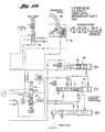
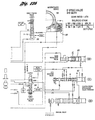
- the hydraulic control system for controlling execution of a 2-3 upshift is shown in Figures 10a, 10b, 11a, 11b, 12a and 12b.
- the new second gear embodied in the five-speed transmission is shown in Figures 10a and 10b.
- the shift solenoid (SS4), shown at 58, can be duty-cycle controlled or actuated as an ON/OFF solenoid.
- an intermediate step 3 is introduced, which initiates the upshifting event of the Simpson planetary gearset 22.
- the overdrive planetary gearset is upshifted, in addition to the first gear ratio of the Simpson sets, giving a gear ratio of 1.85.
- shift solenoid 72 SS3
- the 3-4 shift control valve moves into upshift position. This disconnects line pressure from the overdrive servo release (OSR) side and connects the OSR side with the shift solenoid 58 circuitry.
- This circuitry is called OSR/EX/SS4.
- orifice 74 closed and orifice 76 opened and with the upshifting of valve 84 in bore 215 the OSR side is connected to the duty cycle controlled shift solenoid 58.
- the overdrive servo apply side is always applied with CF-pressure produced by the clutch pressure modulator forward in bore 207.
- the OSR release oil is exhausted through shift solenoid 58.
- the intermediate servo apply side is exhausted over the 1-2 shift valve in bore 203 and the 2-3 upshift valve in bore 204 into the ISA/EX port.
- the intermediate servo release side and the high clutch CL2 are exhausted also over the 1-2 upshift valve 94 in bore 204 and the 2-3 upshift valve 78 (Fig. 11b) in bore 204 into the CR/R/EX port.
- shift solenoid 80 (SS2) is energised.
- the energised shift solenoid 80 moves the 1-2 upshift valve 78 into upshift position. This is shown in Figure 11a.
- the upshifted 1-2 upshift valve 78 connects the intermediate servo apply side (ISA) with CF-pressure and the intermediate servo starts to engage. This initiates the 2-3 upshift by upshifting the Simpson planetary gearset 22, as explained earlier.
- ISA intermediate servo apply side
- the intermediate servo starts to engage.
- This initiates the 2-3 upshift by upshifting the Simpson planetary gearset 22, as explained earlier.
- both elements the overdrive servo as well as the intermediate servo
- independent capacity control would not be possible if a signal pressure controller were to be used.
- With the shift solenoid 58 connected to the OSR side however, independent control of the overdrive band capacity is possible relative to the intermediate band capacity.
- the transmission is in the intermediate step 3 (IS3) stage.
- the downshifting of the overdrive planetary gearset is controlled; first of all by controlling the pressure on the overdrive servo release side by applying a duty cycle to shift solenoid 4.
- This controls capacity of overdrive band 42 and thereby controls the amount of torque applied to OWC1.
- TS turbine speed
- ODS overdrive drum speed
- the upshifting of the Simpson set 22 and the downshifting of the overdrive planetary gearset can be synchronised.
- the coast clutch 50 (CL1) is exhausted over the upshifted coast clutch control valve 82 in bore 201 and upshifted 3-4 shift valve 84 in bore 215.
- the same swap-shift can be controlled in an optional construction without capacity control of the overdrive band. This is accomplished by closing orifice 76 and opening orifice 74. This disconnects the overdrive servo release side from shift solenoid 58 and connects the OSR side over the shift valve in bore 212 to the CL1/B1/EX port. However, this disables the independent control feature of the overdrive band 42, but it produces the option of engaging and releasing the overdrive band through a wide open exhaust. This protects the overdrive band lifetime durability in case of an overloading of the overdrive band using SS4 capacity control. The shift quality, however, will be influenced by this optional shift control method. The same effect is also accomplished without using this optional feature and leaving the shift solenoid turned off.
- the execution of a 2-3 upshift involves a sequence of events and control actions with interaction between the control strategy and the control hardware.
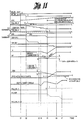
- the timing diagram shown in Figure 13 shows the execution of a 2-3 upshift. Control strategy as well as the hardware behaviour are illustrated in this timing diagram.
- a 2-3 upshift is triggered by the control strategy based on functions of vehicle speed versus throttle position. Desired gear (GR_DS) is changed from second gear to third gear and the shift verification timer (TM_VER_SFT) is loaded. The dynamic EPC value is added for third gear.
- Desired gear GR_DS
- TM_VER_SFT shift verification timer
- the EPC values are raised according to the commanded EPC values.
- the shift verification timer TM_VER_SFT is expired and the gear commanded register GR_CM is changed from second to third gear.
- An initial duty cycle of shift solenoid 58 is loaded into the SS4_DC register. This initial duty cycle is required to prefill the release side of the overdrive servo 88 prior to the shift execution.
- the 2-3 upshift start timer TM_23_STRT is loaded. This timer is required to initiate a start duty cycle independent of the expiration of the shift verification timer TM_VER_SFT. When this timer is expired, a start duty cycle is set prior to closed loop capacity control of the overdrive band 42. An initial slip value, depending on the duty cycle value, could be introduced to the overdrive band in an open loop control manner.
- the overdrive drum speed target value ODS_TRG is calculated based on a function FNODS_CMPT, which contains a multiplier of overdrive drum speed as a function of output shaft speed NOBART. This is calculated based on the actual output shaft speed times the gear ratio after completion of the shift (GRRAT3).
- the gear ratio threshold value RT_23_TRG then is calculated based on a function FN23CMPF, percentage shift complete PCSFTCMPT, versus output shaft speed NOBART in order to initiate the start of closed loop capacity control of the overdrive band using the shift solenoid duty cycle SS4_DC.
- a further gear ratio threshold value RT_SFT_END is calculated to decide the end of closed loop capacity control and to release the overdrive band capacity completely. These values are compared later with the continuously calculated variable RT_TRANS and are used for the above described functions. Shift solenoid flag 2 (FLG_SS_2) is set to 1 and the EPC-RMP timer is loaded. The EPC ramp is now executed.
- Shift solenoid 80 is energised and the 1-2 upshift valve 78 in bore 203 moves into upshift position.
- CF-pressure produced from the clutch pressure modulator forward in bore 207 is applied to the apply side of the intermediate servo 90.
- the characteristic of this forward modulator 92 allows capacity control from zero to maximum capacity.
- the intermediate band is engaged and takes the torque of the sun gear of the Simpson planetary gearset 22.
- the reaction torque on overrunning brake 34 (OWC2) is reduced.
- the output shaft torque follows first the reaction torque characteristic of OWC2.
- the torque phase of the 2-3 swap-shift is initiated (see also Figure 3).
- the overdrive servo release pressure which is actual SS4 output pressure, builds up to a level where no capacity loss on the overdrive band takes place.
- the duty cycle start timer (TM_23_STRT) is expired.
- the start duty cycle (SS4_DC_BRK) is loaded into the SS4_DC register, as seen in Figure 8 and Figure 13.
- SS4_DC_BRK is the break-away duty cycle for overdrive brake capacity.
- the pressure is increased on the release side of the overdrive servo 88 since the shift solenoid duty cycle has been increased.
- the overdrive band capacity can be manipulated by SS4 duty cycle settings and an overdrive drum slip can be introduced prior to closed loop control of the overdrive band capacity.
- the RT_TRANS value is continuously calculated based on turbine speed and output shaft speed.
- the RT_TRANS value starts to decrease when the inertia phase of the 2-3 upshift is started and the torque phase is completed.
- the shift starts with a "shift slope 1" ( Figure 13) which is entirely dependent on the CF pressure settings and the commanded EPC ramp.
- the torque phase of the upshifting event of the Simpson planetary gearset 22 is completed, and the output shaft torque is completely dependent on the applied capacity of the intermediate band.
- the reaction torque on one-way clutch 34 (OWC2) is zero, and the high clutch drum speed (HCDS) starts to decelerate.
- the output shaft torque is reversed since the reaction torque is zero and ISA pressure increases capacity.
- the overdrive drum speed remains at zero speed.
- the duty cycle calculation in each option takes the error between the actual overdrive drum speed ODS and the target overdrive drum speed into account and converts the calculated error in the duty cycle for shift solenoid 58. This adjusts the overdrive band capacity accordingly. Based on the capacity control on the overdrive band 42, a "shift slope 2" is initiated, which begins the downshifting event of the overdrive planetary gearset.
- the timer SS4_END_TMR is loaded and kept high. This timer is needed to compensate for the SS3 pressure exhaust delay time.
- the overdrive servo release pressure is either increased or decreased based on the duty cycle of solenoid 58.
- a second shift slope is introduced due to overdrive band capacity control and the additional overdrive band slip.
- the overdrive drum speed starts to follow the target value ODS_TRG. Independent control of the overdrive planetary gearset is initiated.
- the output shaft torque decreases since the capacity on the overdrive band is decreased as well.
- the RT_TRANS value is smaller than the second ratio threshold RT_SFT_END.
- the closed loop control of the overdrive band is terminated by setting the shift solenoid flag 3 FLG_SS_3 to zero.
- the duty cycle calculation for SS4 shift solenoid 58 is still kept high. This is the initiation of the synchronisation between the downshifting of the overdrive planetary gearset and the upshifting of the Simpson gearset 22.
- Shift solenoid 72 (SS3) is de-energised and the 3-4 upshift valve 84 moves into downshift position.
- the shift solenoid 58 output pressure is disconnected from the overdrive servo release side and line pressure is connected. This reduces the overdrive band capacity completely, and OWC1 takes the remaining inertia and starts to transmit full torque.
- the output pressure of the shift solenoid 58 stays high in order to keep the overdrive servo release area pressurised. From time point t5 to time point t6, downshift accumulation takes place for the overdrive planetary gearset in order to accomplish a smooth one-way clutch engagement of OWC1.
- This accumulation phase is also used to synchronise the downshifting of the overdrive planetary gearset and the upshifting of the Simpson set 22 using feedback control with overdrive drum speed.
- the hatched area of the overdrive servo release area ( Figure 13) indicates the time where independent capacity control takes place following time t3 using open loop control and closed loop control executed by SS4 for the overdrive gearset and the Simpson set.
- the overdrive servo release pressure is line pressure.
- the output shaft torque characteristic shows another negative slope since the overdrive band has zero capacity.
- the EPC_RMP timer has expired and the EPC ramp is terminated.
- the timer SS4_END_TMR can expire before or beyond t7 since this time is used for SS3 pressure exhaust synchronisation.
- timer SS4_END_TMR is expired, the SS4_DC register is set to zero since full line pressure is then connected to the overdrive servo release chamber.
- the overdrive drum has reached engine speed and OWC1 is fully engaged.
- the high clutch drum speed (HCDS) is at zero speed.
- the output shaft torque characteristic is now reversed again since OWC1 then carries full torque.
- the torque phase of the downshifting event is initiated and the 2-3 upshift is complete.
- Time pressure is connected to the overdrive servo release chamber. This is the synchronisation point for the downshifting overdrive gearset and the upshifting Simpson set within the calibration window shown in Figure 3.
- the functioning of the 3-2/4-2 downshift control system is the inverse of the 2-3 upshift event; i.e., the overdrive planetary gearset upshifts and the Simpson set 22 downshifts in a synchronised manner.
- the Simpson set is downshifted by releasing the intermediate servo 90 for band (B2), and the OWC2 engages after the inertia phase.
- the Simpson set 22 is downshifted by releasing the high clutch (CL2).
- the gear ratio is changed from 1.474 to 1.86
- the gear ratio is changed from 1 to 1.86.
- the solenoid stages during a 3-2 downshift is the inverse of the 2-3 upshift, except shift solenoid 58 (SS4) is not duty cycle controlled.
- the 4-2 downshift can be executed either in sequence, which means 4-3-2, or directly as a 4-2 downshift.
- the shift sequence is shown as follows:
- the sequenced 4-3-2 downshift is basically the execution of a 4-3 downshift, which is the same as the 3-2 downshift of the four-speed transmission, followed by the 3-2 (SWAP-SHIFT) downshift.
- the control hardware uses the 5th gear solenoid stage as an intermediate step to initiate the 4-2 downshift, as shown in the above tables.
- Figures 10a, 10b, 11a, 11b, 12a and 12b show the 3-2 downshift hydraulic control system.
- the intermediate servo i.e., band B2
- the high clutch (CL2) is exhausted over the 2-3 upshift valve 94 in bore 204.
- the shift solenoid 3 is energised and the 3-4 upshift valve moves into upshift position.
- the transmission is now in intermediate step 3 shown in Figure 11.
- the overdrive servo release circuit which was previously applied with line pressure, is now exhausted over orifice 76 through the exhaust port of shift solenoid 58.
- the overdrive servo apply side is continuously applied with CF modulator pressure produced by the clutch pressure modulator valve 92 in bore 207.
- the overdrive servo is applied and initiates a 3-2 downshift by upshifting the overdrive planetary gearset.
- the transmission is commanded to execute the second gear solenoid stage as shown in Figures 10a and 10b.
- the duty cycle controlled shift solenoid 58 is de-energised.
- Shift solenoid 80 (SS2) is turned off.
- the shift solenoid 80 de-energised With the shift solenoid 80 de-energised, the 1-2 upshift valve 78 in bore 203 moves into downshift position and the intermediate servo apply pressure is exhausted over the CF/3/4/EX circuit through the ISA/EX port located on the downshifted 2-3 upshift valve 94.
- Shift solenoid SS1 always stays on during the 3-2 downshift event and keeps the high clutch 44 always exhausted, together with upshifted 2-3 upshift valve 94 in bore 204.
- the 3-2 downshift is now complete.
- the 2-3 upshift valve 94 is in the downshift position and D/2/1 pressure is present in the high clutch circuit. This can be seen in Figure 12b where the shift valve 94 in bore 204 is shown in upshift position.
- the overdrive planetary gearset In order to initiate a direct 4-2 downshift, the overdrive planetary gearset has to be upshifted. This can only be accomplished by energising shift solenoid 72 (SS3) first. With shift solenoid 72 turned on, the transmission is in the 5th gear solenoid stage, which corresponds to the 4th gear solenoid stage in the four-speed transmission. When shift solenoid 72 is energised, the overdrive servo release pressure is exhausted over orifice 76 through the exhaust port of shift solenoid 58 (SS4). The overdrive servo apply is pressurised with CF pressure and the overdrive band engages. This initiates the 4-2 downshift.
- shift solenoid 72 shift solenoid 72
- SS4 shift solenoid 58
- the downshifting event of the Simpson planetary gearset is initiated. This is done by energising shift solenoid SS1. Shift solenoid 80 (SS2) stays de-energised. With shift solenoid SS1 energised, the 2-3 upshift valve 94 moves into upshift position. The 1-2 upshift valve 78 in bore 203 is in downshift position. The upshifted 2-3 shift valve 94 in bore 204 opens the ISA/EX port as well as the CR/R/EX port. The intermediate servo apply pressure is exhausted over the ISA/EX port and the high clutch (CL2) is exhausted through the CR/R/EX port. The 4-2 downshift is now complete.
- Figure 14 shows the timing diagram for a 3-2/4-2 downshift. This illustrates the interactive functions of hardware and control strategy during the 3-2/4-2 downshift event. The broken lines in Figure 14 show the additional and actions in a 4-2 downshift.
- a 3-2/4-2 downshift is triggered by the control strategy based on the function of vehicle speed versus throttle position.
- GR_DS is changed from third gear or fourth gear to second gear, and the shift verification timer TM_VER_SFT is loaded.
- the dynamic EPC value is added for second gear.
- the EPC values are raised according to the commanded EPC values.
- the shift verification timer TM_VER_SFT is expired, and the gear commanded register GR_CM is changed from fourth or third to second gear.
- a 3-2/4-2 control timer is loaded. At the same time, overdrive drum speed and turbine speed are monitored to sense the start of the downshifting event. The control timer is required in order to control the 3-2/4-2 downshift independently of the speed signals. This is needed in the event that the speed signals are not available. Shift solenoid flag 3 FLG_SS_3 is set to 1 and the EPC-RMP timer is loaded. The EPC ramp then is executed.
- Shift solenoid 72 (SS3) is energised and the 3-4 shift control valve 84 in bore 215 moves into upshift position.
- CF-pressure produced from the clutch pressure modulator valve (forward) 92 in bore 207 is applied to the overdrive servo apply side, and the overdrive servo starts to stroke.
- the control strategy monitors overdrive drum speed (ODS) and turbine speed (NT).
- the overdrive servo is engaged with CF pressure.
- the characteristic of this modulator valve 92 allows capacity control from 0 to maximum capacity.
- the overdrive band engages and takes the torque of the sun gear from the overdrive planetary gearset.
- the reaction torque on OWC1 relative to the input torque is reduced.
- the output shaft torque is determined first by the reaction torque characteristic of OWC1.
- the torque phase of the 3-2/4-2 swap-shift is initiated with the upshifting of the overdrive planetary gearset.
- the turbine speed value (NT) and the overdrive drum speed value (ODS) start to decrease since the inertia phase of the 3-2/4-2 shift is started and the torque phase is completed. Both speed signals are still being monitored.
- the shift starts with a "shift slope 1" (see Figure 14), which is entirely dependent on the CF pressure settings on the overdrive band according to the commanded EPC ramp.
- the torque phase of the upshifting overdrive planetary gearset is completed and the output shaft torque is completely dependent on the applied capacity on the overdrive band 42.
- the reaction torque on one-way clutch 16 (OWC1) is zero and the overdrive drum speed (ODS) starts to decrease.
- OCS overdrive drum speed
- the output shaft torque is reversed since the reaction torque is zero and OSA pressure is increasing.
- the high drum still stays at zero speed.
- the intermediate band is released and the high clutch is applied for 4th gear.
- the high clutch drum turns clockwise in this case, the same direction as engine speed.
- the shift solenoid flag 2 (FLG_SS_2) is set to zero during a 3-2 downshift.
- the 3-2/4-2 control timer is expired, allowing 3-2/4-2 downshift execution.
- a "shift slope 2" is initiated (see Figure 14).
- the control strategy has sensed that enough capacity is transmitted by the engaged overdrive band. This represents the feedback of the control system for executing a 3-2/4-2 downshift.
- the shift solenoid flag 2, FLG_SS_2 is zero and stays zero.
- the shift solenoid flag 1, FLG_SS_1 is set to 1, initiating the downshift of Simpson planetary gearset 22.
- the intermediate servo apply pressure is exhausted by the de-energised shift solenoid 80 (SS2), which makes the 1-2 upshift valve 78 in bore 203 move to downshift position.
- the shift solenoid SS1 is energised and the 2-3 upshift valve 94 in bore 204 is in downshift position.
- a second shift slope is introduced due to the reduced capacity of the intermediate band 46.
- the high clutch drum speed starts to accelerate from zero rpm.
- the output shaft torque decreases since the capacity of the intermediate band 46 is decreased as well.
- the shift solenoid 80 (SS2) stays de-energised.
- High clutch 44 is pressurised with D/2/1 pressure and the apply side of the intermediate servo is energised with CF pressure.
- the high clutch drum rotates in the direction of the engine speed with the value of engine speed.
- shift solenoid SS1 is energised, the intermediate servo apply pressure and the high clutch pressure are exhausted, and the high clutch drum is first decelerated down to zero speed by the input torque. Then the high clutch is accelerated in the direction opposite to the rotational direction of the engine speed up to the point when overrunning clutch 34 (OWC2) is engaged.
- OBC2 overrunning clutch 34
- the EPC_RMP timer expires and the EPC ramp is terminated.
- the high clutch drum has reached its rotational speed and the overrunning clutch 34 (OWC2) is fully engaged.
- the overdrive drum speed (ODS) is zero.
- the output shaft torque characteristic is now reversed again since OWC2 now carries full torque.
- the torque phase of the downshifting Simpson gearset is initiated and the inertia phase is completed.
- the 3-2/4-2 downshift then is completed.
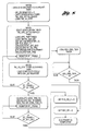
- the flow chart of Figure 9 shows the control strategy during a 3-2/4-2 downshift.
- the five-speed transmission control system controls two independent gearing units of the transmission, the overdrive planetary gearset and the Simpson planetary gearset. These two independent gearing units are compounded together in series.
- the electronic control system controls the upshifting event of the overdrive planetary gearset and the downshifting event of the Simpson planetary gearset during a 2-3 upshift, and vice-versa during a 3-2 downshift. Both events are synchronised and capacity control is executed during the synchronisation process.
- a conventional hydraulic control system is not capable of executing such a "swap-shift." With the improved control system of this invention, this shift execution is accomplished by applying electronic control and feedback control techniques. A further advantage of this control system is the independent capacity control.
- the present invention will make it possible to provide improved fuel economy and performance without adding additional gearing compared to conventional transmissions and without increasing complexity of the control system.
Landscapes
- Engineering & Computer Science (AREA)
- General Engineering & Computer Science (AREA)
- Mechanical Engineering (AREA)
- Physics & Mathematics (AREA)
- Fluid Mechanics (AREA)
- Control Of Transmission Device (AREA)
- Structure Of Transmissions (AREA)
Claims (16)
- Transmission automatique destinée à un véhicule comportant des engrenages définissant de multiples trajets d'écoulement de couple entre un moteur commandé par un papillon des gaz et un arbre de sortie de couple (38) comprenant un premier ensemble de train (P2, figure 2b) présentant au moins trois rapports de marche avant et un second ensemble de train (P1, figure 2b) présentant au moins deux rapports de marche avant, lesdits ensembles de trains (P2, P1) étant disposés en relation en série dans lesdits trajets d'écoulement de couple, lesdits trajets d'écoulement de couple comprenant un convertisseur de couple (10, 12, 14) comportant un impulseur (10) entraíné par ledit moteur et une turbine (12) reliée en entraínement audit second ensemble de train (P1),
un embrayage (CL1, CL2, 50, 44) et des moyens de freins (B1, 42 ; B2, 46) actionnés par pression, destinés à établir et à supprimer des changements de rapports dans lesdits engrenages comprenant un premier moyen de frein à réaction (B2, 46) destiné à ancrer un élément de réaction dudit premier ensemble de train (P2) durant un fonctionnement dans un rapport intermédiaire dudit premier ensemble de train (P2) et un second moyen de frein à réaction (B1, 42) destiné à ancrer un élément de réaction dudit second ensemble de train (P1) durant un fonctionnement dans le plus élevé desdits deux rapports de marche avant dudit second ensemble de train (P1),
ledit premier moyen de frein à réaction (B2, 46) comprenant un premier servomécanisme de frein (90) comportant un premier piston d'asservissement et des chambres de pression de libération et d'application de frein sur des côtés opposés dudit premier piston d'asservissement,
ledit second moyen de frein de réaction (B1, 42) comprenant un second servomécanisme de frein (88) comportant un second piston d'asservissement et des chambres de pression d'application et de libération de frein sur des côtés opposés dudit second piston d'asservissement de frein,
un système de vannes de commande (figures 9, 10, 11a, 11b, 12a, 12b) destiné à commander la distribution de pression vers lesdits embrayage et moyens de freins comprenant lesdites chambres de pression d'application pour lesdits premier et second servomécanismes de freins (90, 88) et ladite chambre de pression de libération pour ledit second servomécanisme de frein (88), ledit système de vannes comprenant une source de pression de ligne (figures 9, 11a, 12a) et un moyen de vanne de régulation de pression principale (68) destiné à réguler ladite pression de ligne,
caractérisée en ce que la transmission automatique comprend en outre un moyen de commande de pression électronique (66) communiquant avec ledit moyen de vanne de régulation de pression principale (68) en vue d'établir une pression de commande déterminée par la mise en oeuvre de variables comprenant la vitesse du véhicule, la vitesse de la turbine et la position du papillon des gaz du moteur, un passage de pression de commande électronique (figure 12b) communiquant avec ledit moyen de commande de pression électronique (66),
un premier moyen de vanne de modulation de pression (207, figures 10a, 10b, 11a, 11b, 12a, 12b) dans ledit système de vannes de commande, destiné à établir une première pression de commande modulée comprenant une surface d'application de pression en communication avec ledit passage de pression de commande électronique,
un second moyen de vanne de modulation de pression (58) dans ledit système de commande, destiné à établir une seconde pression de commande modulée,
ledit système de vannes comprenant des moyens de vannes de commande de changement de rapport (72, 78) destinés à réaliser une communication commandée entre lesdites chambres de pression d'application desdits premier et second servomécanismes de freins (90, 88) et ledit premier moyen de vanne de modulation de pression (207) et entre ladite chambre de pression de libération dudit second servomécanisme de frein (88) et ledit second moyen de vanne de modulation de pression (58), d'où il résulte que les capacités d'action des freins durant l'application et la libération desdits premier et second moyens de freins à réaction (B2, B1) sont commandées de façon indépendante, l'une par rapport à l'autre, afin de réaliser une transition sans à-coup du couple de réaction de l'un desdits ensembles de trains vers l'autre durant des changements de rapports vers le haut et des changements de rapports vers le bas. - Transmission selon la revendication 1, dans laquelle ledit moyen de commande de pression électronique (66) comprend un processeur électronique (figures 11a, 12a), un premier moyen de capteur de vitesse (56) destiné à détecter la vitesse dudit élément de réaction dudit second ensemble de train (P1), un second moyen de capteur de vitesse (97) destiné à détecter une vitesse qui est fonctionnellement liée à la vitesse de l'arbre de sortie, et un troisième capteur de vitesse (TSS) destiné à détecter la vitesse de la turbine,
ledit processeur électronique étant sensible aux valeurs détectées par lesdits capteurs pour ladite vitesse de l'élément de réaction du second ensemble de train, ladite vitesse qui est fonctionnellement liée à la vitesse de l'arbre de sortie et ladite vitesse de la turbine afin d'élaborer une valeur pour ladite pression de commande qui a un effet sur ladite commande indépendante des capacités d'action des freins desdits premier et second moyens de freins à réaction (B2, B1) durant des changements de rapports vers le haut et des changements de rapports vers le bas. - Transmission selon la revendication 2, dans laquelle ledit système de vannes de commande comprend des moyens de vannes de changement de rapport (SS1, SS2, SS3, SS4) en vue de commander les signaux provenant dudit processeur déterminés par lesdites variables en vue de commander la distribution et la libération de pression vers lesdits embrayage et moyens de freins durant les changements de rapports,
l'un desdits moyens de vannes de changement de rapport (SS4), ledit moyen de vanne de modulation supplémentaire (58), comportant des parties communes et étant sensible aux signaux d'instruction de changement de rapport provenant dudit moyen de commande (66) en vue d'établir ladite pression de commande modulée supplémentaire. - Transmission selon la revendication 2, dans laquelle la mise en prise de chacun desdits premier et second moyens de freins à réaction (B2, B1) comprend une phase de couple et une phase d'inertie, ladite commande indépendante des capacités d'action des freins desdits moyens de freins à réaction (B2, B1) établissant le commencement de ladite phase d'inertie pour ledit premier ensemble de train (P2) après l'achèvement d'une partie de ladite phase d'inertie dudit second ensemble de train (P1) durant des changements de rapports vers le bas.
- Transmission selon la revendication 2, dans laquelle la mise en prise de chacun desdits premier et second moyens de freins à réaction (B1, B2) comprend une phase de couple et une phase d'inertie, ladite commande indépendante des capacités d'action desdits moyens de freins à réaction établissant le commencement de ladite phase d'inertie dudit second ensemble de train (P1) après l'achèvement d'une partie de ladite phase d'inertie dudit premier ensemble de train et établissant la fin de ladite phase d'inertie dudit second ensemble de train (P1) avant la fin de ladite phase d'inertie dudit premier ensemble de train (P2) durant des changements de rapports vers le haut.
- Transmission selon la revendication 5, dans laquelle ladite commande indépendante des capacités d'action desdits moyens de freins à réaction (B2, B1) établit la fin de ladite phase de couple dudit second ensemble de train (P1) et la fin de ladite phase d'inertie dudit premier ensemble de train (P2) durant un intervalle de temps calibré lorsque ledit changement de rapport vers le haut est achevé.
- Transmission selon la revendication 5, dans laquelle ledit système de vannes comprend un moyen de vanne de commande de changement de rapport (72) destiné à établir une communication entre ladite source de pression de la ligne et ladite chambre de pression de libération de frein pour ledit second servomécanisme de frein (88) lors de l'achèvement de ladite phase de couple pour ledit second ensemble de train (P1) durant des changements de rapports vers le haut en libérant ainsi totalement ledit second servomécanisme de frein (88).
- Transmission selon la revendication 1, dans laquelle ledit premier ensemble de train (P2) comporte un élément de réaction de rapport bas (32) en plus dudit élément de réaction pour lesdits moyens de freins à réaction et moyen d'embrayage (CL3) destinés à établir un rapport d'entraínement unitaire dans ledit premier ensemble de train (P2),
ledit second ensemble de train (P1) étant un simple ensemble de train planétaire de surmultiplication, ledit élément de réaction dudit second ensemble de train étant une roue solaire, et un simple moyen d'embrayage d'ensemble de train planétaire (OWC1, 50) destiné à établir un rapport d'entraínement unitaire dans ledit second ensemble de train (P1). - Transmission selon la revendication 8, dans laquelle ledit simple moyen d'embrayage d'ensemble de train planétaire est un accouplement à roue libre (OWC1) entre deux éléments de délivrance de couple dudit simple ensemble de train planétaire.
- Transmission selon la revendication 8, dans laquelle ledit moyen de commande de pression électronique (66) comprend un processeur électronique, un premier moyen de capteur de vitesse (56) destiné à détecter une vitesse qui est fonctionnellement liée à la vitesse dudit élément de réaction dudit second ensemble de train et un second moyen de capteur de vitesse (97) destiné à détecter la vitesse de l'arbre de sortie, et un troisième capteur de vitesse (TSS) destiné à détecter la vitesse de la turbine,
ledit processeur électronique étant sensible aux valeurs détectées par lesdits capteurs pour la vitesse de l'élément de réaction dudit second ensemble de train, ladite vitesse qui est fonctionnellement liée à la vitesse de sortie et ladite vitesse de la turbine afin d'engendrer une valeur pour ladite pression de commande qui a un effet sur ladite commande indépendante des capacités d'action des freins desdits premier et second moyens de freins à réaction (B2, B1) durant lesdits changements de rapports vers le haut et changements de rapports vers le bas. - Transmission selon la revendication 10, dans laquelle la mise en prise de chacun desdits premier et second moyens de freins à réaction (B2, B1) comprend une phase de couple et une phase d'inertie, ladite commande indépendante des capacités d'action des freins desdits moyens de freins à réaction établissant le commencement de ladite phase d'inertie pour ledit premier ensemble de train (P2) après l'achèvement d'une partie de ladite phase d'inertie dudit second ensemble de train (P1) durant lesdits changements de rapports vers le bas.
- Transmission selon la revendication 10, dans laquelle la mise en prise de chacun desdits premier et second moyens de freins à réaction (B2, B1) comprend une phase de couple et une phase d'inertie, ladite commande indépendante des capacités d'action des freins desdits moyens de freins à réaction établissant le commencement de ladite phase d'inertie dudit second ensemble de train (P1) après l'achèvement d'une partie de ladite phase d'inertie dudit premier ensemble de train (P2) et établissant la fin de ladite phase d'inertie dudit second ensemble de train avant la fin de ladite phase d'inertie dudit premier ensemble de train durant lesdits changements de rapports vers le haut.
- Transmission selon la revendication 12, dans laquelle ladite commande indépendante des capacités d'action desdits moyens de freins à réaction (B1, B2) établit la fin de ladite phase de couple dudit second ensemble de train (P2) et la fin de ladite phase d'inertie dudit premier ensemble de train (P1) durant un intervalle de temps calibré lors de l'achèvement desdits changements de rapports vers le haut.
- Transmission selon la revendication 12, dans laquelle lesdits moyens de vannes de commande de changement de rapport (72, 78) comprennent des éléments de vannes de changement de rapport mobiles et des actionneurs à solénoïde pour lesdits éléments de vannes de changement de rapport, lesdits moyens de vannes de commande de changement de rapport (72, 78) établissant une communication entre ladite source de pression de ligne et ladite chambre de pression de libération des freins destinée audit second servomécanisme de frein (88) lors de l'achèvement de ladite phase de couple pour ledit second ensemble de train durant ledit changement de rapport vers le haut en libérant ainsi totalement ledit second servomécanisme de frein (88).
- Transmission selon la revendication 1, dans laquelle lesdits engrenages définissent au moins des premier, second, troisième et quatrième rapports globaux de marche avant dans lesdits trajets d'écoulement de couple, lesdits embrayage et moyens de freins actionnés par pression (42, 44, 46, 48) comprennent un embrayage à friction (CL2, 4b) reliant deux éléments de délivrance de couple sélectifs dudit premier ensemble de train (P2) afin d'établir une unité de rapport pour ledit premier ensemble de train, ledit système de vannes de commande commandant également la distribution de pression vers ledit embrayage à friction (CL2),
ledit moyen de vanne de commande de changement de rapport (72) réalisant également une distribution sélective de ladite pression de ligne vers ledit embrayage à friction (CL2) durant le fonctionnement dudit premier ensemble de train (P2) dans le plus élevé desdits trois rapports de marche avant de celui-ci, d'où il résulte qu'une application et une libération desdits premier et second moyens de freins à réaction (B2, B1) et l'application dudit embrayage à friction (CL2) sont commandées de façon indépendante, l'une par rapport à l'autre, afin de réaliser des changements de rapports vers le bas sans à-coup depuis ledit quatrième rapport global de marche avant vers ledit second rapport global de marche avant. - Transmission selon la revendication 15, dans laquelle ledit moyen de commande de pression électronique (66) comprend un processeur électronique (figures 11a, 12a), un premier moyen de capteur de vitesse (56) destiné à détecter la vitesse dudit élément de réaction dudit second ensemble de train (P1), un second moyen de capteur de vitesse (97) destiné à détecter une vitesse qui est fonctionnellement liée à la vitesse de l'arbre de sortie, et un troisième capteur de vitesse (TSS) destiné à détecter la vitesse de la turbine,
ledit processeur électronique étant sensible aux valeurs détectées par lesdits capteurs pour ladite vitesse de l'élément de réaction du second ensemble de train, ladite vitesse qui est fonctionnellement liée à la vitesse de l'arbre de sortie et ladite vitesse de la turbine afin d'engendrer une valeur pour ladite pression de commande qui a un effet sur ladite commande desdits premier et second moyens de freins à réaction (B2, B1) et dudit embrayage à friction (CL2) durant des changements de rapports vers le bas depuis ledit quatrième rapport global de marche avant vers ledit second rapport global de marche avant.
Applications Claiming Priority (2)
| Application Number | Priority Date | Filing Date | Title |
|---|---|---|---|
| US549438 | 1983-11-07 | ||
| US08/549,438 US5642283A (en) | 1995-10-27 | 1995-10-27 | Multiple ratio transmission with swap-shift controls |
Publications (3)
| Publication Number | Publication Date |
|---|---|
| EP0770800A2 EP0770800A2 (fr) | 1997-05-02 |
| EP0770800A3 EP0770800A3 (fr) | 1998-07-22 |
| EP0770800B1 true EP0770800B1 (fr) | 2002-07-17 |
Family
ID=24193036
Family Applications (1)
| Application Number | Title | Priority Date | Filing Date |
|---|---|---|---|
| EP96307762A Expired - Lifetime EP0770800B1 (fr) | 1995-10-27 | 1996-10-28 | Une transmission automatique |
Country Status (3)
| Country | Link |
|---|---|
| US (1) | US5642283A (fr) |
| EP (1) | EP0770800B1 (fr) |
| DE (1) | DE69622341T2 (fr) |
Families Citing this family (23)
| Publication number | Priority date | Publication date | Assignee | Title |
|---|---|---|---|---|
| JP3158970B2 (ja) * | 1995-07-10 | 2001-04-23 | 三菱自動車工業株式会社 | 自動変速機の変速制御方法 |
| US5835875A (en) | 1995-10-27 | 1998-11-10 | Ford Global Technologies, Inc. | Swap-shift control system for a multiple ratio transmission |
| JP3470508B2 (ja) * | 1996-05-29 | 2003-11-25 | トヨタ自動車株式会社 | 自動変速機の変速制御装置 |
| US6122583A (en) | 1997-12-23 | 2000-09-19 | Ford Global Technologies, Inc. | Upshift and downshift control valve system for multiple ratio automatic transmission |
| US6007445A (en) * | 1998-02-03 | 1999-12-28 | Ford Global Technologies, Inc. | Static forward and reverse engagement control system for a multiple ratio automatic transmission |
| US6292731B1 (en) * | 1998-07-27 | 2001-09-18 | Ford Global Technologies, Inc. | Automatic shift control system for an automatic transmission including a select-shift manual control |
| US6254510B1 (en) * | 2000-03-22 | 2001-07-03 | Ford Global Technologies, Inc. | Coasting downshift control strategy for a multiple-ratio automatic transmission |
| US6283891B1 (en) | 2000-04-07 | 2001-09-04 | Ford Global Technologies, Inc. | Automatic transmission for an automotive vehicle with a shift control for launch assist and manual upshifts |
| US6301538B1 (en) | 2000-06-07 | 2001-10-09 | Ford Global Technologies, Inc. | Swap shift multiple-ratio automatic transmission |
| US6393350B1 (en) * | 2001-08-10 | 2002-05-21 | Ford Global Technologies, Inc. | Powertrain controller using a feed-forward torque calculation |
| US6961646B2 (en) * | 2003-10-31 | 2005-11-01 | Ford Global Technologies, Llc | Automatic transmission control system with direct electronic swap-shift control |
| US7107135B2 (en) * | 2003-10-31 | 2006-09-12 | Ford Global Technologies, Llc | Auxiliary gearset shift progression command generator for a swap-shift automatic transmission |
| WO2005119096A2 (fr) * | 2004-06-01 | 2005-12-15 | Carne Gary S | Modulation de pression de transmission par clapet a orifice traversant |
| US7198586B2 (en) * | 2004-12-10 | 2007-04-03 | Ford Motor Company | Transmission having multiple ratio planetary gear unit in series with an auxiliary gear unit |
| US7789798B2 (en) * | 2006-09-27 | 2010-09-07 | Chrysler Group Llc | Transmission upshift control method |
| US7608013B2 (en) * | 2006-09-29 | 2009-10-27 | Chrysler Group Llc | Transmission downshift control method |
| US7632215B2 (en) * | 2006-12-05 | 2009-12-15 | Chrysler Group Llc | Transmission downshift swap-shift control |
| DE102007021193A1 (de) * | 2007-05-05 | 2008-11-06 | Zf Friedrichshafen Ag | Verfahren zum Betreiben eines Automatgetriebes mit mehreren Übersetzungsstufen |
| JP2009236262A (ja) * | 2008-03-28 | 2009-10-15 | Aisin Aw Co Ltd | 自動変速機の変速制御装置 |
| US8321101B2 (en) * | 2009-05-05 | 2012-11-27 | Ford Global Technologies, Llc | Temperature dependent minimum transmission input speed |
| JP5985142B2 (ja) * | 2010-07-30 | 2016-09-06 | いすゞ自動車株式会社 | 惰行制御装置 |
| US10197117B2 (en) | 2016-01-11 | 2019-02-05 | Cnh Industrial America Llc | Temperature-based clutch protection from centrifugal head pressure inhibiting clutch disengagement |
| JP6848841B2 (ja) * | 2017-11-30 | 2021-03-24 | トヨタ自動車株式会社 | 車両の制御装置 |
Family Cites Families (24)
| Publication number | Priority date | Publication date | Assignee | Title |
|---|---|---|---|---|
| US4007648A (en) * | 1975-04-24 | 1977-02-15 | Ford Motor Company | Five-speed automatic transmission |
| DE3417784A1 (de) * | 1984-05-14 | 1985-11-14 | Ford-Werke AG, 5000 Köln | Hydraulisches steuerventilsystem fuer ein mehrgaengiges, selbsttaetig schaltendes hydrokinetisch-mechanisches wechselgetriebe fuer kraftfahrzeuge |
| JPS61241558A (ja) * | 1985-04-18 | 1986-10-27 | Toyota Motor Corp | 車輌用自動変速機の変速制御方法 |
| US4653350A (en) * | 1985-11-29 | 1987-03-31 | General Motors Corporation | Adaptive direct pressure shift control for a motor vehicle transmission |
| JPS62165051A (ja) * | 1986-01-13 | 1987-07-21 | Toyota Motor Corp | 自動変速機の制御方法 |
| JP2696819B2 (ja) * | 1986-10-08 | 1998-01-14 | 日産自動車株式会社 | 自動変速機の変速シヨツク軽減装置 |
| US4817473A (en) * | 1987-03-11 | 1989-04-04 | Ford Motor Company | Hydraulic control valve system for an automatic multiple-speed transmission with a lockup torque converter and electronically operated lockup control |
| JPH0621620B2 (ja) * | 1987-07-28 | 1994-03-23 | 日産自動車株式会社 | 自動変速機の歯車変速装置 |
| DE3814547A1 (de) * | 1988-04-29 | 1989-11-09 | Ford Werke Ag | Steuerventil fuer eine hydraulisch betaetigbare kupplung eines automatischen kraftfahrzeuggetriebes |
| US4856383A (en) * | 1988-06-06 | 1989-08-15 | Ford Motor Company | Coast clutch control for multiple speed automatic transmission |
| US4884471A (en) * | 1988-06-23 | 1989-12-05 | Ford Motor Company | Four speed ratio automatic power transmission |
| US5176592A (en) * | 1989-01-23 | 1993-01-05 | Toyota Jidosha Kabushiki Kaisha | Speed changing gear device having two independent gear assemblies |
| JP2739121B2 (ja) * | 1989-09-05 | 1998-04-08 | トヨタ自動車株式会社 | 自動変速機の変速制御装置 |
| JP2966003B2 (ja) * | 1989-09-06 | 1999-10-25 | トヨタ自動車株式会社 | 自動変速機の変速制御装置 |
| DE3931025A1 (de) * | 1989-09-16 | 1991-03-28 | Porsche Ag | Automatikgetriebe fuer ein kraftfahrzeug |
| US5070747A (en) * | 1989-12-26 | 1991-12-10 | General Motors Corporation | Adaptive powered downshift control of an automatic transmission |
| JP2813027B2 (ja) * | 1990-04-20 | 1998-10-22 | マツダ株式会社 | 自動変速機の変速制御装置 |
| US5334117A (en) * | 1990-09-28 | 1994-08-02 | Mazda Motor Corporation | Automatic transmission with an add-on extension to increase the number of gear ratios |
| US5224907A (en) * | 1990-09-28 | 1993-07-06 | Jatco Corporation | Automatic transmission |
| US5167592A (en) * | 1991-05-10 | 1992-12-01 | Jatco Corporation | Automatic transmission |
| US5131902A (en) * | 1991-09-06 | 1992-07-21 | Ford Motor Company | Nonsynchronous five-speed transaxle for automotive vehicles |
| JPH0587230A (ja) * | 1991-09-25 | 1993-04-06 | Mazda Motor Corp | 自動変速機の変速制御装置 |
| JPH05306756A (ja) * | 1992-04-30 | 1993-11-19 | Mazda Motor Corp | 自動変速機の制御装置 |
| US5553694A (en) * | 1994-10-14 | 1996-09-10 | Ford Motor Company | Multiple ratio automatic transmission and torque converter |
-
1995
- 1995-10-27 US US08/549,438 patent/US5642283A/en not_active Expired - Lifetime
-
1996
- 1996-10-28 DE DE69622341T patent/DE69622341T2/de not_active Expired - Lifetime
- 1996-10-28 EP EP96307762A patent/EP0770800B1/fr not_active Expired - Lifetime
Also Published As
| Publication number | Publication date |
|---|---|
| EP0770800A3 (fr) | 1998-07-22 |
| EP0770800A2 (fr) | 1997-05-02 |
| DE69622341T2 (de) | 2002-11-21 |
| US5642283A (en) | 1997-06-24 |
| DE69622341D1 (de) | 2002-08-22 |
Similar Documents
| Publication | Publication Date | Title |
|---|---|---|
| EP0770800B1 (fr) | Une transmission automatique | |
| EP0821189B1 (fr) | Transmission à plusieurs vitesses avec commande simultanée d'une pluralité de trains | |
| EP0825366B1 (fr) | Système de commande de changement entre des unités d'engrenage pour transmissions à plusieurs rapports | |
| EP0707164B1 (fr) | Système de commande d'un changement de vitesse pour une transmission automatique à plusieurs rapports | |
| EP0436978B1 (fr) | Méthode pour commander des changements de vitesses dans une transmission automatique | |
| US5157608A (en) | Electronic control system for multiple ratio transmission including circuit pressure control | |
| EP0322111B1 (fr) | Rétrogradation d'embrayage à embrayage en dépendance d'une séquence d'évènements dans une transmission automatique à commande électronique | |
| US5046383A (en) | Acceleration-based control of power-on clutch-to-clutch upshifting in an automatic transmission | |
| US5303616A (en) | Electronically controlled bypass clutch based on percent-shift-completion for a torque converter | |
| EP0231994B1 (fr) | Dispositif de commande pour le changement à une vitesse inférieure d'une boîte de vitesses de véhicule automobile en frein-moteur entre deux rappôts d'engrenage à changement par des embrayages | |
| EP0978672B1 (fr) | Système de commande pour transmission automatique à plusieurs vitesses | |
| US4989477A (en) | Double transition closed throttle downshift control in an automatic transmissions | |
| US5113343A (en) | Sequenced control of double transition powered downshifting in an automatic transmission | |
| US5133227A (en) | Method of power-on downshifting of automatic transmission interrelated with temporary torque down of engine | |
| US6385520B1 (en) | Control strategy and method for independently controlling friction element actuators for an automatic transmission | |
| US6122583A (en) | Upshift and downshift control valve system for multiple ratio automatic transmission | |
| EP0626529B1 (fr) | Transmission pour véhicule automobile | |
| US6370463B1 (en) | Strategy for controlling ratio changes in a swap-shift automatic transmission | |
| EP0707163B1 (fr) | Système de commande de changement de vitesse pour une transmission automatique à plusieurs vitesses avec des gammes de vitesse manuelles | |
| EP1431624B1 (fr) | Dispositif de commande de changement de vitesses pour transmission automatique | |
| EP0783079B1 (fr) | Méthode de commande du changement de vitesse pour transmission automatique | |
| EP0736707B1 (fr) | Dispositif de commande de changement de vitesses pour transmission automatique | |
| US5596495A (en) | Gearshift controller for automatic transmission | |
| US5349885A (en) | Hydraulic control system for controlling line pressure based on backtorque and throttle rate in an automatic transmission | |
| US5704874A (en) | Shift control method for automatic transmission |
Legal Events
| Date | Code | Title | Description |
|---|---|---|---|
| PUAI | Public reference made under article 153(3) epc to a published international application that has entered the european phase |
Free format text: ORIGINAL CODE: 0009012 |
|
| AK | Designated contracting states |
Kind code of ref document: A2 Designated state(s): DE FR GB |
|
| PUAL | Search report despatched |
Free format text: ORIGINAL CODE: 0009013 |
|
| AK | Designated contracting states |
Kind code of ref document: A3 Designated state(s): DE FR GB |
|
| RHK1 | Main classification (correction) |
Ipc: F16H 61/06 |
|
| 17P | Request for examination filed |
Effective date: 19981127 |
|
| 17Q | First examination report despatched |
Effective date: 20001110 |
|
| GRAG | Despatch of communication of intention to grant |
Free format text: ORIGINAL CODE: EPIDOS AGRA |
|
| GRAG | Despatch of communication of intention to grant |
Free format text: ORIGINAL CODE: EPIDOS AGRA |
|
| GRAH | Despatch of communication of intention to grant a patent |
Free format text: ORIGINAL CODE: EPIDOS IGRA |
|
| GRAH | Despatch of communication of intention to grant a patent |
Free format text: ORIGINAL CODE: EPIDOS IGRA |
|
| GRAA | (expected) grant |
Free format text: ORIGINAL CODE: 0009210 |
|
| AK | Designated contracting states |
Kind code of ref document: B1 Designated state(s): DE FR GB |
|
| REG | Reference to a national code |
Ref country code: GB Ref legal event code: FG4D |
|
| REG | Reference to a national code |
Ref country code: GB Ref legal event code: 746 Effective date: 20020729 |
|
| REF | Corresponds to: |
Ref document number: 69622341 Country of ref document: DE Date of ref document: 20020822 |
|
| ET | Fr: translation filed | ||
| REG | Reference to a national code |
Ref country code: FR Ref legal event code: D6 |
|
| PLBE | No opposition filed within time limit |
Free format text: ORIGINAL CODE: 0009261 |
|
| STAA | Information on the status of an ep patent application or granted ep patent |
Free format text: STATUS: NO OPPOSITION FILED WITHIN TIME LIMIT |
|
| 26N | No opposition filed |
Effective date: 20030422 |
|
| REG | Reference to a national code |
Ref country code: FR Ref legal event code: TP |
|
| REG | Reference to a national code |
Ref country code: FR Ref legal event code: CD Ref country code: FR Ref legal event code: CA |
|
| PGFP | Annual fee paid to national office [announced via postgrant information from national office to epo] |
Ref country code: DE Payment date: 20101029 Year of fee payment: 15 |
|
| PGFP | Annual fee paid to national office [announced via postgrant information from national office to epo] |
Ref country code: GB Payment date: 20110930 Year of fee payment: 16 Ref country code: FR Payment date: 20111005 Year of fee payment: 16 |
|
| GBPC | Gb: european patent ceased through non-payment of renewal fee |
Effective date: 20121028 |
|
| REG | Reference to a national code |
Ref country code: FR Ref legal event code: ST Effective date: 20130628 |
|
| PG25 | Lapsed in a contracting state [announced via postgrant information from national office to epo] |
Ref country code: DE Free format text: LAPSE BECAUSE OF NON-PAYMENT OF DUE FEES Effective date: 20130501 Ref country code: GB Free format text: LAPSE BECAUSE OF NON-PAYMENT OF DUE FEES Effective date: 20121028 |
|
| REG | Reference to a national code |
Ref country code: DE Ref legal event code: R119 Ref document number: 69622341 Country of ref document: DE Effective date: 20130501 |
|
| PG25 | Lapsed in a contracting state [announced via postgrant information from national office to epo] |
Ref country code: FR Free format text: LAPSE BECAUSE OF NON-PAYMENT OF DUE FEES Effective date: 20121031 |