EP0770810B1 - Rohrkompensator - Google Patents
Rohrkompensator Download PDFInfo
- Publication number
- EP0770810B1 EP0770810B1 EP96307596A EP96307596A EP0770810B1 EP 0770810 B1 EP0770810 B1 EP 0770810B1 EP 96307596 A EP96307596 A EP 96307596A EP 96307596 A EP96307596 A EP 96307596A EP 0770810 B1 EP0770810 B1 EP 0770810B1
- Authority
- EP
- European Patent Office
- Prior art keywords
- ball
- socket
- balls
- bellows
- cup
- Prior art date
- Legal status (The legal status is an assumption and is not a legal conclusion. Google has not performed a legal analysis and makes no representation as to the accuracy of the status listed.)
- Expired - Lifetime
Links
Images


Classifications
-
- F—MECHANICAL ENGINEERING; LIGHTING; HEATING; WEAPONS; BLASTING
- F16—ENGINEERING ELEMENTS AND UNITS; GENERAL MEASURES FOR PRODUCING AND MAINTAINING EFFECTIVE FUNCTIONING OF MACHINES OR INSTALLATIONS; THERMAL INSULATION IN GENERAL
- F16L—PIPES; JOINTS OR FITTINGS FOR PIPES; SUPPORTS FOR PIPES, CABLES OR PROTECTIVE TUBING; MEANS FOR THERMAL INSULATION IN GENERAL
- F16L27/00—Adjustable joints; Joints allowing movement
- F16L27/10—Adjustable joints; Joints allowing movement comprising a flexible connection only
- F16L27/107—Adjustable joints; Joints allowing movement comprising a flexible connection only the ends of the pipe being interconnected by a flexible sleeve
- F16L27/11—Adjustable joints; Joints allowing movement comprising a flexible connection only the ends of the pipe being interconnected by a flexible sleeve the sleeve having the form of a bellows with multiple corrugations
-
- F—MECHANICAL ENGINEERING; LIGHTING; HEATING; WEAPONS; BLASTING
- F01—MACHINES OR ENGINES IN GENERAL; ENGINE PLANTS IN GENERAL; STEAM ENGINES
- F01D—NON-POSITIVE DISPLACEMENT MACHINES OR ENGINES, e.g. STEAM TURBINES
- F01D11/00—Preventing or minimising internal leakage of working-fluid, e.g. between stages
- F01D11/005—Sealing means between non relatively rotating elements
-
- F—MECHANICAL ENGINEERING; LIGHTING; HEATING; WEAPONS; BLASTING
- F01—MACHINES OR ENGINES IN GENERAL; ENGINE PLANTS IN GENERAL; STEAM ENGINES
- F01D—NON-POSITIVE DISPLACEMENT MACHINES OR ENGINES, e.g. STEAM TURBINES
- F01D9/00—Stators
- F01D9/06—Fluid supply conduits to nozzles or the like
- F01D9/065—Fluid supply or removal conduits traversing the working fluid flow, e.g. for lubrication-, cooling-, or sealing fluids
Definitions
- the present invention relates generally to gas turbine engines, and, more specifically, to expansion joints therein for accommodating differential thermal movement of fluid carrying components.
- a gas turbine engine includes a compressor for compressing air which is suitably mixed with fuel and ignited in a combustor for generating hot combustion gases which flow downstream through one or more turbines.
- Various components of the turbines are cooled by using a portion of the compressed air bled from the compressor for use as cooling air.
- the cooling air bled from the compressor is channeled through suitable conduits and joints to the various components requiring cooling, with many of the conduits being subjected to differential thermal movement and vibratory excitation during operation.
- Fluid carrying joints such as those used in the bleed air system take various conventional forms including ball and socket joints which allow relative pivotal movement, with the joints also being conventionally configured for also accommodating differential translation between adjacent ends of the conduits (see, for example, documents US-A-2 616 728 and US-A-2 712 456).
- traditional graphite ball joints are subject to undesirable leakage in view of the various differential pivotal and translation movement to which the joint is subjected to during operation, as well as due to vibratory excitation. As the ball joints wear during operation, leakage therefrom becomes more and more of a problem until the traditional graphite ball joints require replacement at substantial cost.
- an expansion joint for joining together first and second fluid conduits comprising:
- FIG. 1 Illustrated schematically in Figure 1 is an axial, partly sectional view of an exemplary aircraft turbofan gas turbine engine 10.
- the engine 10 includes in serial flow communication a fan 10a, low pressure compressor 10b, high pressure compressor 10c, combustor 10d, high pressure turbine 10e, and low pressure turbine 10f operatively joined together with a pair of rotor shafts and being conventional in configuration and operation.
- air 12 flows downstream through the fan 10a and is compressed in the compressors 10b,c, with the majority of the compressed air being suitably mixed with fuel and ignited in the combustor 10d for generating combustion gases which are channeled through the turbines 10e,f for powering the engine in flight.
- selected components of the low pressure turbine 10f are cooled in a conventional manner, and are supplied with a portion of the compressed air 12 bled from a suitable stage of the high pressure compressor 10c for providing cooling air 12b to the low pressure turbine 10f through a bleed air system.
- the bleed air system includes an annular, multi-component air manifold 14 which receives the cooling air 12b and suitably disperses the cooling air to the various components within the low pressure turbine 10f.
- Figure 2 illustrates an exemplary embodiment of the manifold 14 surrounding the low pressure turbine 10f shown in phantom.
- the cooling air 12b is suitably channeled into the manifold 14 through conventional inlets 14a thereof.
- the air is discharged from the manifold 14 into the low pressure turbine 10f through conventional outlets 14b in the form of radially inwardly extending and axially inclined tubes.
- the cooling air 12b is distributed circumferentially around the manifold 14 through interconnected fluid carrying conduits indicated generally at 16.
- a plurality of expansion joints 18 are circumferentially spaced apart around the circumference of the manifold 14 between adjacent ones of the manifold outlets 14b to accommodate differential thermal movement due to expansion and contraction during operation.
- the expansion joints 18 could instead be located in each of the manifold outlets 14b, one of which is illustrated in phantom at the 12:00 position in Figure 2.
- the expansion joints 18 are identically configured for effecting multi-degree-of-freedom (MDF) motion between the adjacent portions of the connected conduits.
- MDF multi-degree-of-freedom
- Figure 3 illustrates an exemplary one of the expansion joints 18 wherein the interconnected conduits are defined as a first conduit 16a which enters the joint 18 from one side, and a second conduit 16b which enters the joint 18 from an opposite side.
- the joint 18 carries therethrough and between the conduits 16a,b the cooling air 12b.
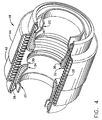
- a cutaway perspective view of the expansion joint 18 itself is illustrated in Figure 4
- the MDF joint 18 includes a tubular first fitting 20 having at a proximal end thereof a cylindrical first sleeve 20a for being conventionally fixedly joined to the end of the first conduit 16a by welding or brazing for example.
- a first ball 20b Disposed at an opposite, distal end of the first fitting 20 is a first ball 20b which is a truncated spherical section having a convex annular outer surface which is smooth.
- a substantially identical tubular second fitting 22 includes at a proximal end thereof a cylindrical second sleeve 22a which is fixedly joined to a corresponding end of the second conduit 16b.
- the second fitting 22 includes a second ball 22b at its distal end which is also a truncated spherical section having a convex annular outer surface which is also smooth.
- a first socket 24 receives the first ball 20b for pivotal and rotary, or torsional, movement therein and is complementary in shape, and also in the form of a truncated spherical section having a matching annular concave inner surface.
- a similar second socket 26 receives the second ball 22b for pivotal and rotary, or torsional, movement therein, with the second socket 26 being complementary in shape to the second ball 22b, and also being a truncated spherical section having a matching concave smooth inner surface.
- the first and second fittings 20, 22 are axially spaced apart from each other, and a tubular bellows 28 extends therebetween and is disposed coaxially with the first and second sockets 24, 26.
- the bellows 28 has axially opposite first and second distal ends 28a and 28b, with the first end 28a being fixedly and sealingly joined to the first socket 24, and the second end 28b being similarly fixedly and sealingly joined to the second socket 26.
- the bellows 28 sealingly joins together the sockets 24, 26 and the cooperating balls 20b, 22b, for accommodating axial differential movement therebetween. Additional differential movement is permitted between the sockets 24, 26, with the balls 20b, 22b being pivotable and rotatable in the respective first and second sockets 24, 26.
- MDF multi-degree-of-freedom
- the bellows 28 may be sized and configured for having a suitable spring constant so that during assembly, the bellows 28 is initially compressed and thereafter creates compressive loads in opposite directions against the sockets 24, 26 for maintaining seating of the respective balls 20b, 22b therein.
- the sockets 24, 26 may be simply a suitable metal either alone or containing a suitable wear resistant spray coating thereon such as Copper-Nickel-lndium or Nickel-Graphite which are commercially available.
- a suitable wear resistant spray coating thereon such as Copper-Nickel-lndium or Nickel-Graphite which are commercially available.
- improved sealing for extended periods of time may be obtained by using a separate, replaceable sealing member.
- the expansion joint 18 includes a tubular first sleeve or cup 30 which surrounds the first ball 20b and has at a distal end thereof a first base 30a in the form of a flat disk with a center hole, and at an opposite proximal end thereof a cylindrical first rim 30b which is suitably fixedly joined to the bellows first end 28a by conventional resistance welding for example.
- a tubular second sleeve or cup 32 surrounds the second ball 22b and has at a distal end thereof a second base 32a in the form of a flat disk with a center hole, and at an opposite proximal end thereof a cylindrical second rim 32b suitably fixedly joined to the bellows second end 28b by resistance welding for example.
- a replaceable annular first seal 34 is complementary in configuration with the inside of the first cup 30 and is suitably seated therein, and has a spherical inner surface which defines the first socket 24 which receives in pivotal sealing contact the first ball 20b.
- a replaceable annular second seal 36 is complementary in configuration with the inside of the second cup 32 and is suitably seated therein, and has a spherical inner surface defining the second socket 26 which receives in pivotal sealing contact the second ball 22b.
- the first and second seals 34, 36 may be formed of any conventional material for providing an effective sliding sealing fit with the respective balls 20b, 22b.
- the seals 34, 36 are preferably conventional graphite seals which are simply press-fit into the respective first and second cups 30, 32 and are separately replaceable upon disassembly of the first and second balls 20b, 22b from their respective first and second sockets 24, 26. In this way, the seals 34, 36 may be readily replaced as required during service.
- first and second seals 34, 36 are preferably identical to each other and each has a respective cylindrical access hole 34a, 36a disposed coextensively with the respective entrances to the first and second sockets 24, 26.
- the first and second access holes 34a, 36a are suitably larger in diameter than the respective diameters of the first and second balls 20b, 22b for axially receiving the balls 20b, 22b during assembly for seating against the respective first and second sockets 24, 26.
- respective first and second retainers 38 and 40 in the form of split rings are disposed adjacent to the respective first and second cup rims 30b, 32b for retaining the first and second balls 20b, 22b in their respective first and second sockets 24, 26.
- the retainers 38, 40 also retain the seals 34, 36 in their respective cups 30, 32.
- each of the balls 20b, 22b is free to pivot or rotate torsionally in its respective socket 24, 26 in a conventional ball-and-socket joint arrangement.
- the respective sockets 24, 26 are flexibly joined together through the common bellows 28 joined at opposite ends to the first and second cups 30, 32.
- the two balls 20b and 22b are also allowed to translate axially relative to each other as well as laterally in the radial direction.
- the resulting expansion joint 18 therefore allows substantial multi-degree-of-freedom movement between the two captured balls 20b and 22b joined to the respective ends of the first and second conduits 16a, 16b for ease of assembly and for accommodating differential thermal movement therebetween including expansion and contraction.
- the ball-and-socket joints and the bellows 28 therebetween ensures effective sealing of the cooling air 12b between the conduits 16a, 16b, which can improve over time as the balls 20b, 22b wear into their respective sockets 24, 26 formed in the graphite seals 34, 36.
- the seats defined by the sockets 24, 26 are self-renewing since abrasion or wear thereof improves the seating of the respective balls 20b, 22b therein.
- the bellows 28 is inherently flexible and axially compressible so that during assembly it may be initially compressed for effecting compressive loads in opposite directions on the first and second cups 30, 32 to urge the first and second seals 34, 36 in sealing contact with the first and second balls 20b, 22b. This firmly seats the balls in their respective sockets.
- the pressure of the cooling air 12b itself inside the expansion joint 18 additionally provides pressure forces acting against the bases of the cups 30, 32 to additionally urge the seals 34, 36 in contact with the balls 20b, 22b for additionally improving the pressure seating thereof. Accordingly, effective and long lasting sealing is maintained over the useful life of the joint 18 irrespective of the differential thermal-movement between the conduits 16a,b and the respective balls joined to the ends thereof.
- the bellows 28 may be protected from damage by including first and second telescoping annular shrouds 42, 44 fixedly joined at proximal ends thereof to the respective first and second cup rims 30b, 32b.
- the proximal ends of the shrouds 42, 44 surround the ends of the bellows 28 and are conventionally resistance welded to the bellows ends which in turn are resistance welded to the cups 30, 32.
- the distal ends of the shrouds 42, 44 preferably overlap each other for a suitable axial distance for telescopically accommodating differential axial movement of the first and second cups 30, 32 which expands and contracts the bellows 28.
- the distal end portions of the shrouds 42, 44 are preferably cylindrical and are suitably sized in diameter to form a sliding close fit therebetween to effect air damping of the joint 18 upon axial differential movement.
- the volume between the shrouds 42, 44 and the bellows 28 is thereby suitably enclosed, with telescoping of the shrouds 42, 44 therefor compressing or expanding the air trapped therein, with corresponding leakage or rushing of the air between the overlapping joint to uniquely effect air damping. In the vibratory environment of a gas turbine engine, this air damping can effectively reduce vibratory response of the expansion joint 18.
- the overlapping of the shrouds 42, 44 also restrains lateral bending of the bellows 28, with lateral offset between the first and second conduits 16a,b being primarily accommodated by pivoting of the respective balls in their sockets. Preventing lateral bending of the bellows 28 can improve the useful life thereof.
- each of the shrouds 42, 44 may be used to advantage in an exemplary embodiment for capturing the retainers 38, 40.
- each of the shrouds 42, 44 includes a respective first and second integral lip 42a, 44a at the proximal ends thereof. These lips may be simply formed by plastically rolling the ends of the shrouds 42, 44 to create a suitable radius around the circumference thereof.
- the lips 42a, 44a are preferably spaced axially from the respective first and second cup rims 30b, 32b so that the retainers 38, 40 may be secured within the lips for retaining both the balls 20b, 22b and their cooperating seals 34, 36 in the respective cups 30, 32.
- each of the retainers 38, 40 has a generally V-shaped radial section, with a first leg adjoining the respective lips 42a, 44a and trapped thereby, and a second leg adjoining the respective seals 34, 36 and balls 20b, 22b.
- the inclined legs are generally parallel to the back sides of the respective balls 20b, 22b for providing a large contact surface area for retaining the balls in their sockets.
- the retainers 38, 40 may be formed of suitable thin sheet metal for reducing weight of the joint 18. The split retainers 38, 40 may be simply removed through the respective orifices defined by the lips 42a, 44a, which then allows the respective balls to be removed from their sockets for access to the seals 34, 36 which may then be removed and replaced as desired.
- the envelope of the joint 18 illustrated in Figure 3 may be reduced if desired by relocating the bellows 28 axially between the two cups 30, 32 (not shown).
- a conventional flow liner (not shown) may be installed between the central orifices of the cups 30, 32 for reducing pressure drop and reducing the risk of damage to the bellows 28 from inside.
Landscapes
- Engineering & Computer Science (AREA)
- General Engineering & Computer Science (AREA)
- Mechanical Engineering (AREA)
- Joints Allowing Movement (AREA)
Claims (8)
- Expansionsverbindung (18) zum Verbinden erster (16a) und zweiter (16b) Fluidleitungen, enthaltend:ein rohrförmiges erstes Paßstück (20), das an seinem nahegelegenen Ende eine erste Hülse (20a) für eine feste Verbindung mit der ersten Leitung und an seinem entfernten Ende eine erste Kugel (20b) aufweist,ein rohrförmiges zweites Paßstück (22), das an seinem nahegelegenen Ende eine zweite Hülse (22a) für eine feste Verbindung mit der zweiten Leitung und an seinem entfernten Ende eine zweite Kugel (22b) aufweist, die mit axialem Abstand von der ersten Kugel in Strömungsverbindung damit angeordnet ist,einen ersten Sockel (24), der die erste Kugel für eine Schwenkbewegung darin aufnimmt,einen zweiten Sockel (26), der die zweite Kugel für eine Schwenkbewegung darin aufnimmt,einen rohrförmigen Faltenbalg (28), der koaxial mit den ersten und zweiten Sockeln angeordnet ist und gegenüberliegende erste und zweite entfernte Enden (28a, 28b) hat, wobei der Faltenbalg eine unterschiedliche Bewegung zwischen den ersten und zweiten Sockeln aufnimmt, wobei die ersten und zweiten Kugeln darin schwenkbar sind, gekennzeichnet durch:einen rohrförmigen ersten Becher (30), der eine erste Basis (30a) an seinem entfernten Ende und einen zylindrischen ersten Rand (30b) an seinem gegenüberliegenden nahegelegenen Ende aufweist, der mit dem ersten Ende des Faltenbalgs fest verbunden ist,einen rohrförmigen zweiten Becher (32), der eine zweite Basis (32a) an seinem entfernten Ende und einen zylindrischen zweiten Rand (32b) an seinem gegenüberliegenden nahegelegenen Ende aufweist, der mit dem zweiten Ende des Faltenbalgs fest verbunden ist,eine ringförmige erste Dichtung (34), die komplementär zu dem ersten Becher ist und darin sitzt und eine sphärische Innenfläche aufweist, die den ersten Sockel (24) bildet, der die erste Kugel in einem schwenkbaren Dichtungskontakt aufnimmt,eine ringförmige zweite Dichtung (36), die komplementär zu dem zweiten Becher ist und darin sitzt und eine sphärische Innenfläche aufweist, die den zweiten Sockel (26) bildet, der die zweite Kugel in einem schwenkbaren Dichtungskontakt aufnimmt, und wobeidie erste Kugel ferner ein zylindrisches erstes Zugangsloch (34a) aufweist, das in gleicher Ausdehnung mit dem ersten Sockel (24) angeordnet ist und grösser als die erste Kugel (20b) ist zum axialen Aufnehmen der ersten Kugel für einen Sitz gegen den ersten Sockel, unddie zweite Kugel ferner ein zylindrisches zweites Zugangsloch (36a) aufweist, das in gleicher Ausdehnung mit dem zweiten Sockel (26) angeordnet ist und grösser als die zweite Kugel (22b) ist zum axialen Aufnehmen der zweiten Kugel für einen Sitz gegen den zweiten Sockel.
- Verbindung nach Anspruch 1, wobei ferner erste und zweite Haltevorrichtungen (38, 40) vorgesehen sind, die neben den ersten bzw. zweiten Becherrändern (30b, 32b) angeordnet sind zur Halterung der ersten und zweiten Kugeln (20b, 22b) in den entsprechenden ersten und zweiten Sockeln (24, 26).
- Verbindung nach Anspruch 1 oder 2, wobei ferner erste und zweite Teleskopmäntel (42, 44) vorgesehen sind, die an ihren nahegelegenen Enden mit den ersten bzw. zweiten Becherrändern (30b, 32b) fest verbunden sind, wobei sich ihre entfernten Enden überlappen zum teleskopartigen Aufnehmen von unterschiedlicher Axialbewegung der ersten und zweiten Becher, die den Faltenbalg expandiert und kontraktiert.
- Verbindung nach Anspruch 3, wobei die ersten und zweiten Mäntel (42, 44) neben ihren entfernten Enden zylindrisch und so bemessen sind, daß sie eine Gleitpassung dazwischen bilden, um bei der unterschiedlichen Axialbewegung eine Luftdämpfung der Verbindung zu bewirken.
- Verbindung nach einem der vorstehenden Ansprüche, wobei der Faltenbalg (28) axial kompressibel ist, um Druckkräfte in entgegengesetzten Richtungen auf die ersten und zweiten Becher (30, 32) zu bewirken, um die ersten und zweiten Dichtungen (34, 36) in einen dichtenden Kontakt mit den ersten und zweiten Kugeln zu drücken.
- Verbindung nach einem der vorstehenden Ansprüche, wobei die ersten und zweiten Dichtungen (34, 36) Graphit aufweisen, der in einer Presspassung in die ersten und zweiten Becher (30, 32) gedrückt ist, und die getrennt austauschbar sind nach einer Demontage der Kugeln aus den Sockeln nach einer Entfernung der Haltevorrichtungen.
- Verbindung nach Anspruch 2 oder irgendeinem Anspruch, der direkt oder indirekt davon abhängig ist, die ferner erste und zweite Lippen (42a, 44a) aufweist, die an den ersten bzw. zweiten nahegelegenen Mantelenden gebildet sind und neben den ersten und zweiten Becherrändern (30b, 32b) angeordnet sind, und die ersten und zweiten Haltevorrichtungen (38, 40) in den Lippen befestigt sind zum Haltern sowohl der Kugeln als auch der kooperierenden Dichtungen in den entsprechenden Bechern.
- Verbindung nach Anspruch 7, wobei die ersten und zweiten Haltevorrichtungen (38, 40) im allgemeinen V-förmige radiale Schnitte haben, wobei ein erster Schenkel an die entsprechenden Lippen angrenzt und ein zweiter Schenkel an die entsprechenden Dichtungen und Kugeln angrenzt.
Applications Claiming Priority (2)
| Application Number | Priority Date | Filing Date | Title |
|---|---|---|---|
| US08/547,004 US5584511A (en) | 1995-10-23 | 1995-10-23 | Multi-degree-of-freedom expansion joint |
| US547004 | 1995-10-23 |
Publications (2)
| Publication Number | Publication Date |
|---|---|
| EP0770810A1 EP0770810A1 (de) | 1997-05-02 |
| EP0770810B1 true EP0770810B1 (de) | 2002-01-30 |
Family
ID=24182956
Family Applications (1)
| Application Number | Title | Priority Date | Filing Date |
|---|---|---|---|
| EP96307596A Expired - Lifetime EP0770810B1 (de) | 1995-10-23 | 1996-10-18 | Rohrkompensator |
Country Status (4)
| Country | Link |
|---|---|
| US (1) | US5584511A (de) |
| EP (1) | EP0770810B1 (de) |
| JP (1) | JP3884511B2 (de) |
| DE (1) | DE69618898T2 (de) |
Cited By (1)
| Publication number | Priority date | Publication date | Assignee | Title |
|---|---|---|---|---|
| CN110541992A (zh) * | 2019-09-19 | 2019-12-06 | 高严慧 | 一种补偿器 |
Families Citing this family (24)
| Publication number | Priority date | Publication date | Assignee | Title |
|---|---|---|---|---|
| US5772254A (en) * | 1995-12-20 | 1998-06-30 | Eg&G Pressure Science, Inc. | Modular joint, with a replaceable sealing sleeve |
| MXPA04002410A (es) * | 2001-09-13 | 2004-05-31 | Gen Electric | Metodos y aparatos para determinaciones de rigidez de fuelles con gualderas con base en modelos. |
| US6715297B1 (en) * | 2002-09-20 | 2004-04-06 | General Electric Company | Methods and apparatus for supporting high temperature ducting |
| US7104717B2 (en) * | 2004-03-11 | 2006-09-12 | Balco, Inc. | Roof joint cover |
| US20050264145A1 (en) * | 2004-05-28 | 2005-12-01 | Croft William F | Food storage and serving device |
| FR2883599B1 (fr) * | 2005-03-23 | 2010-04-23 | Snecma Moteurs | Dispositif de liaison entre une enceinte de passage d'air de refroidissement et un aubage de distributeur dans une turbomachine |
| US20060266049A1 (en) * | 2005-05-27 | 2006-11-30 | General Electric Company | Expansion joint and method of assembling same |
| DE102005024414B3 (de) * | 2005-05-27 | 2007-01-11 | Airbus Deutschland Gmbh | Verbindungsstück zur gelenkigen Verbindung einer ersten und einer zweiten Rohrleitung |
| US7762509B2 (en) * | 2007-10-18 | 2010-07-27 | United Technologies Corp. | Gas turbine engine systems involving rotatable annular supports |
| US8459936B2 (en) | 2007-11-30 | 2013-06-11 | United Technologies Corporation | Flexible seal for gas turbine engine system |
| JP5582747B2 (ja) * | 2009-09-14 | 2014-09-03 | 三菱重工業株式会社 | 配管ジョイント、ガスタービンおよび固有振動数調整方法 |
| ES2393720T3 (es) * | 2010-09-20 | 2012-12-27 | Fiat Powertrain Technologies S.P.A. | Unidad turbosobrealimentadora con un componente auxiliar asociado para un motor de combustión interna |
| US9284889B2 (en) | 2011-11-16 | 2016-03-15 | United Technologies Corporation | Flexible seal system for a gas turbine engine |
| US9085982B2 (en) | 2012-03-19 | 2015-07-21 | Mitsubishi Hitachi Power Systems, Ltd. | Gas turbine |
| JP2014111991A (ja) * | 2014-01-08 | 2014-06-19 | Mitsubishi Heavy Ind Ltd | 配管ジョイント、およびガスタービン |
| CN107849933B (zh) | 2015-07-09 | 2020-04-28 | 和谐工业有限责任公司 | 用于控制旋转约束的波纹状球形接头组件挠性界面 |
| US10378379B2 (en) | 2015-08-27 | 2019-08-13 | General Electric Company | Gas turbine engine cooling air manifolds with spoolies |
| US10167885B2 (en) | 2016-03-21 | 2019-01-01 | United Technologies Corporation | Mechanical joint with a flanged retainer |
| US10422279B2 (en) | 2016-11-04 | 2019-09-24 | Senior Ip Gmbh | Spherical compensator junction assembly for high pressure ducting system |
| US10704718B2 (en) | 2017-01-25 | 2020-07-07 | Unison Industries, Llc | Flexible joints assembly with flexure rods |
| US10578015B2 (en) | 2017-01-25 | 2020-03-03 | Unison Industries, Llc | Flexible joints assembly with flexure rods |
| US12392289B2 (en) * | 2017-05-22 | 2025-08-19 | Rtx Corporation | Active bleed flow modulation |
| FR3123092B1 (fr) * | 2021-05-18 | 2025-04-11 | Safran Helicopter Engines | Dispositif d’entrainement d’un flux d’air principal pour une turbomachine d’aeronef |
| US20240209782A1 (en) * | 2022-12-22 | 2024-06-27 | Raytheon Technologies Corporation | Electrically boosted turbine cooling air |
Family Cites Families (12)
| Publication number | Priority date | Publication date | Assignee | Title |
|---|---|---|---|---|
| US2475834A (en) * | 1945-05-05 | 1949-07-12 | Solar Aircraft Co | Flexible pipe joint |
| US2616728A (en) * | 1948-02-20 | 1952-11-04 | Solar Aircraft Co | Flexible exhaust pipe joint |
| US2712456A (en) * | 1952-02-28 | 1955-07-05 | Rohr Aircraft Corp | Exhaust duct with detachable bellows |
| US3837685A (en) * | 1973-01-02 | 1974-09-24 | J Miller | Pipe expansion and repair fitting |
| US4350372A (en) * | 1980-01-21 | 1982-09-21 | Logsdon Duane D | Expansion coupling for large diameter plastic pipes |
| GB2107816B (en) * | 1981-10-24 | 1984-08-22 | Leslie Maurice Ward | Universal joint |
| US4553775A (en) * | 1983-04-26 | 1985-11-19 | Pressure Science Incorporated | Resilient annular seal with supporting liner |
| GB8528105D0 (en) * | 1985-11-14 | 1985-12-18 | Birch F P | Flexible joint |
| US4893847A (en) * | 1988-07-05 | 1990-01-16 | Stainless Steel Products, Inc. | Bearing seal for universal ball joint |
| US5069487A (en) * | 1990-02-08 | 1991-12-03 | Flexonics Inc. | Flexible connector |
| US5286071A (en) * | 1992-12-01 | 1994-02-15 | General Electric Company | Bellows sealed ball joint |
| US5370427A (en) * | 1994-01-10 | 1994-12-06 | General Electric Company | Expansion joint for fluid piping with rotation prevention member |
-
1995
- 1995-10-23 US US08/547,004 patent/US5584511A/en not_active Expired - Lifetime
-
1996
- 1996-10-18 EP EP96307596A patent/EP0770810B1/de not_active Expired - Lifetime
- 1996-10-18 DE DE69618898T patent/DE69618898T2/de not_active Expired - Fee Related
- 1996-10-22 JP JP27848196A patent/JP3884511B2/ja not_active Expired - Lifetime
Cited By (1)
| Publication number | Priority date | Publication date | Assignee | Title |
|---|---|---|---|---|
| CN110541992A (zh) * | 2019-09-19 | 2019-12-06 | 高严慧 | 一种补偿器 |
Also Published As
| Publication number | Publication date |
|---|---|
| JPH09178072A (ja) | 1997-07-11 |
| DE69618898D1 (de) | 2002-03-14 |
| DE69618898T2 (de) | 2002-09-19 |
| US5584511A (en) | 1996-12-17 |
| JP3884511B2 (ja) | 2007-02-21 |
| EP0770810A1 (de) | 1997-05-02 |
Similar Documents
| Publication | Publication Date | Title |
|---|---|---|
| EP0770810B1 (de) | Rohrkompensator | |
| US6679045B2 (en) | Flexibly coupled dual shell bearing housing | |
| EP1193370B1 (de) | Turboladerwelle mit zentrierenden Verbindungen | |
| US5480162A (en) | Axial load carrying brush seal | |
| US5611577A (en) | Bellows sealed ball joint and method of forming | |
| EP1149987A2 (de) | Turbinengehäuse | |
| US11754210B2 (en) | Gimbaled flexure for spherical flex joints | |
| US20050047910A1 (en) | Methods and apparatus to reduce seal rubbing within gas turbine engines | |
| EP1484495B1 (de) | Kardanische Verbindung eines Strahlrohrs | |
| US20180202590A1 (en) | Gimbaled flexure for spherical flex joints | |
| US3967829A (en) | Seal ring | |
| US6709024B1 (en) | Method and apparatus for assembling couplings for transferring fluids | |
| US12158226B2 (en) | Flexible alignment sealing coupling | |
| RU2351771C2 (ru) | Турбореактивный двигатель | |
| EP1085247A2 (de) | Dichtringe für eine verlustarme flexible Kupplung von Gasleitungen | |
| US20050212283A1 (en) | Low profile tension style flexible joint | |
| EP4177505B1 (de) | Verbindungsanordnung und verfahren zur herstellung davon | |
| US6457934B2 (en) | Connector tube for a turbine rotor cooling circuit | |
| US5098133A (en) | Tube coupling with swivelable piston | |
| EP1726864A1 (de) | Dehnverbindung für eine Gasturbine und Verfahren zu deren Zusammenbau | |
| US11788655B2 (en) | Tube coupling | |
| US10625871B1 (en) | Dynamic movement tube connection system | |
| US5232337A (en) | Slip joint for maintaining concentricity | |
| EP3656989A1 (de) | Flanschspannungsreduzierungsmerkmale | |
| US12129945B2 (en) | Tube assembly |
Legal Events
| Date | Code | Title | Description |
|---|---|---|---|
| PUAI | Public reference made under article 153(3) epc to a published international application that has entered the european phase |
Free format text: ORIGINAL CODE: 0009012 |
|
| AK | Designated contracting states |
Kind code of ref document: A1 Designated state(s): DE FR GB |
|
| 17P | Request for examination filed |
Effective date: 19971103 |
|
| 17Q | First examination report despatched |
Effective date: 19991118 |
|
| GRAG | Despatch of communication of intention to grant |
Free format text: ORIGINAL CODE: EPIDOS AGRA |
|
| GRAG | Despatch of communication of intention to grant |
Free format text: ORIGINAL CODE: EPIDOS AGRA |
|
| GRAH | Despatch of communication of intention to grant a patent |
Free format text: ORIGINAL CODE: EPIDOS IGRA |
|
| GRAH | Despatch of communication of intention to grant a patent |
Free format text: ORIGINAL CODE: EPIDOS IGRA |
|
| GRAA | (expected) grant |
Free format text: ORIGINAL CODE: 0009210 |
|
| REG | Reference to a national code |
Ref country code: GB Ref legal event code: IF02 |
|
| AK | Designated contracting states |
Kind code of ref document: B1 Designated state(s): DE FR GB |
|
| REF | Corresponds to: |
Ref document number: 69618898 Country of ref document: DE Date of ref document: 20020314 |
|
| ET | Fr: translation filed | ||
| PLBE | No opposition filed within time limit |
Free format text: ORIGINAL CODE: 0009261 |
|
| STAA | Information on the status of an ep patent application or granted ep patent |
Free format text: STATUS: NO OPPOSITION FILED WITHIN TIME LIMIT |
|
| 26N | No opposition filed | ||
| PGFP | Annual fee paid to national office [announced via postgrant information from national office to epo] |
Ref country code: DE Payment date: 20071130 Year of fee payment: 12 |
|
| PGFP | Annual fee paid to national office [announced via postgrant information from national office to epo] |
Ref country code: GB Payment date: 20071029 Year of fee payment: 12 Ref country code: FR Payment date: 20071017 Year of fee payment: 12 |
|
| GBPC | Gb: european patent ceased through non-payment of renewal fee |
Effective date: 20081018 |
|
| REG | Reference to a national code |
Ref country code: FR Ref legal event code: ST Effective date: 20090630 |
|
| PG25 | Lapsed in a contracting state [announced via postgrant information from national office to epo] |
Ref country code: DE Free format text: LAPSE BECAUSE OF NON-PAYMENT OF DUE FEES Effective date: 20090501 |
|
| PG25 | Lapsed in a contracting state [announced via postgrant information from national office to epo] |
Ref country code: FR Free format text: LAPSE BECAUSE OF NON-PAYMENT OF DUE FEES Effective date: 20081031 |
|
| PG25 | Lapsed in a contracting state [announced via postgrant information from national office to epo] |
Ref country code: GB Free format text: LAPSE BECAUSE OF NON-PAYMENT OF DUE FEES Effective date: 20081018 |