EP0770852A1 - Agencement pour positionner un élément d'écriture dans un appareil d'enregistrement - Google Patents
Agencement pour positionner un élément d'écriture dans un appareil d'enregistrement Download PDFInfo
- Publication number
- EP0770852A1 EP0770852A1 EP96250241A EP96250241A EP0770852A1 EP 0770852 A1 EP0770852 A1 EP 0770852A1 EP 96250241 A EP96250241 A EP 96250241A EP 96250241 A EP96250241 A EP 96250241A EP 0770852 A1 EP0770852 A1 EP 0770852A1
- Authority
- EP
- European Patent Office
- Prior art keywords
- signal
- pen
- pulse
- arrangement according
- drive motor
- Prior art date
- Legal status (The legal status is an assumption and is not a legal conclusion. Google has not performed a legal analysis and makes no representation as to the accuracy of the status listed.)
- Granted
Links
- 238000005259 measurement Methods 0.000 claims abstract description 41
- 230000005540 biological transmission Effects 0.000 claims description 6
- 241001422033 Thestylus Species 0.000 description 9
- 239000002360 explosive Substances 0.000 description 6
- 238000010586 diagram Methods 0.000 description 5
- 238000002955 isolation Methods 0.000 description 4
- 238000013459 approach Methods 0.000 description 3
- 230000008859 change Effects 0.000 description 3
- 230000007423 decrease Effects 0.000 description 3
- 230000001105 regulatory effect Effects 0.000 description 3
- 230000003213 activating effect Effects 0.000 description 2
- 230000001276 controlling effect Effects 0.000 description 2
- 238000012937 correction Methods 0.000 description 2
- 238000004519 manufacturing process Methods 0.000 description 2
- 238000000034 method Methods 0.000 description 2
- 230000008569 process Effects 0.000 description 2
- 238000001228 spectrum Methods 0.000 description 2
- 230000004913 activation Effects 0.000 description 1
- 230000008901 benefit Effects 0.000 description 1
- 238000006243 chemical reaction Methods 0.000 description 1
- 238000013461 design Methods 0.000 description 1
- 238000011161 development Methods 0.000 description 1
- 230000000694 effects Effects 0.000 description 1
- 230000010355 oscillation Effects 0.000 description 1
- 238000012545 processing Methods 0.000 description 1
- 230000009467 reduction Effects 0.000 description 1
- 238000000926 separation method Methods 0.000 description 1
- 230000003595 spectral effect Effects 0.000 description 1
Images

Classifications
-
- G—PHYSICS
- G01—MEASURING; TESTING
- G01D—MEASURING NOT SPECIALLY ADAPTED FOR A SPECIFIC VARIABLE; ARRANGEMENTS FOR MEASURING TWO OR MORE VARIABLES NOT COVERED IN A SINGLE OTHER SUBCLASS; TARIFF METERING APPARATUS; MEASURING OR TESTING NOT OTHERWISE PROVIDED FOR
- G01D15/00—Component parts of recorders for measuring arrangements not specially adapted for a specific variable
- G01D15/24—Drives for recording elements and surfaces not covered by G01D5/00
Definitions
- the invention relates to an arrangement for positioning a stylus in a registration device for recording the time profile of a measurement signal that can be switched on according to the preamble of patent claim 1.
- EP 0 078 367 discloses a recording / display apparatus for industrial processes with a movable device which, with its position, indicates the size of a process or process condition to be monitored and can be driven by a stepper motor which can be actuated by sequential pulses from a clock pulse device , is known which with a feedback device for developing a feedback signal corresponding to the position of the movable device within a total measuring range of positions of this device with a deviation device for generating a deviation signal which indicates the difference between the feedback signal and a measurement signal.
- a dead band device responsive to the deviation signal is provided for developing a control or regulating signal, which responds when the deviation signal lies outside a predetermined dead band around the position represented by the measurement signal.
- circuit device responsive to the initial development of the control or regulating signal for activating the stepping motor in order to produce a limited correction effect of a predetermined extent for returning the device to the position represented by the measurement signal and a second circuit device responsive to the control and regulating signal for activating of the stepper motor is provided beyond the predetermined extent, which responds when the deviation signal at the end of a predetermined period of time after the activation of the stepper motor by the first device is still outside the dead band.
- This known apparatus suffers from the disadvantage that the bandwidth of the measurement signal predetermined by the deadband device manifests itself as a recording error between the actual measurement signal and the recorded signal. Changes in the measurement signal within the bandwidth of the dead band device are not recorded.
- the bandwidth of the deadband device is a measure of the recording accuracy or the quality class of the recording device.
- the pen recorder is basically suitable for recording measurement signals from potentially explosive areas.
- the pen recorder is equipped with at least one first unit, consisting of a movable pen carriage which, depending on the size of a measurement signal, can be moved in a direction perpendicular to the direction of movement of a curve sheet, a servo unit which has a potentiometer for generating a position feedback signal assigned to the position of the pen carriage, and is made in one piece with a servo amplifier, which generates the difference between the position feedback signal of the potentiometer and the measurement signal and controls a servo motor in a predetermined direction so that the difference becomes zero, the pen carriage being correspondingly movable and a leading axis being between both sides of one end a printed circuit board is arranged and on which the pen carriage is detachably mounted, the pen carriage being provided with a pen which is analogous to the size of the measurement signal on the curve sheet tt can record, with a measurement signal with a Analog / digital
- Optocouplers are provided between the A / D converters and the microprocessor, via which the digital signal representing the measurement signal is transmitted.
- the digital output signal of the microprocessor is converted back into an analog signal via a D / A converter, a servomotor being controlled with the amplitude of the converted analog signal.
- the positioning of the writing systems in such a pen recorder can be represented very precisely following the measurement signal, but disadvantageously very expensive, since an A / D converter and a D / A converter are to be assigned to each individual measurement channel, the reproducibility of the measurement signal being based on it Figure as a recorded signal is limited by the data bit width of the digital output of the A / D converter and the digital input of the D / A converter.
- the effort required for 2n converter modules for the implementation of analog-digital-analog increases.
- the invention is therefore based on the object of specifying means for positioning a stylus in a registration device in which the measurement signal is electrically isolated from the drive means of the stylus and which enables the highest possible accuracy of the measurement signal to be mapped onto the recording signal with little effort.
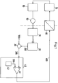
- the registration device itself has known means for transporting a record carrier, at least one writing system consisting of an electric drive motor 90, a gear device for converting the rotary drive movement of the drive motor 90 into a translational movement of the stylus 10 transversely to the transport direction of the record carrier and means for receiving the Pen 10, which are arranged following the translational movement of the output of the gear device.
- the registration device is equipped with means 20 for determining the current pen position with output of a pen position signal 200 adequate for the pen position and means for controlling the drive motor 90 in accordance with the measurement signal 100 as a function of the current pen position signal 200.
- a summation device 30 is provided, which is supplied with the pen position signal 200 and the measurement signal 100 on the input side and outputs a control deviation 300 on the output side as a difference between the measurement signal 100 and the pen position signal 200.
- the control deviation 300 is a measure of the instantaneous value of the error between the measurement signal 100 to be recorded and the measurement value actually recorded on the basis of the current pen position, which is quantified by the pen position signal 200.
- the summation device 30 is followed by a pulse width modulator 40, which can be constructed from a ramp generator 42 and a comparator circuit 41 with two inputs, the control deviation 300 being connected to the first input of the comparator circuit 41 and the output signal of the ramp generator to the second input of the comparator circuit 41 42 is connected.
- the output signal of the Ramp generator 42 is referred to as ramp signal 500.
- the comparator circuit 41 has an output which is likewise the output of the pulse width modulator 40 and from which a pulse width modulated control signal 400 can be tapped.
- the pulse width modulator 40 is followed by means 60 for the electrical isolation of the pulse width modulated control signal 400, which is electrically connected to the measurement signal 100, the pen position signal 200 and the control deviation 300, from the means for controlling the drive motor 90.
- the means 60 for electrical isolation is followed by a signal converter 70, which is suitable for converting the pulse-width-modulated control signal into a signal voltage corresponding to the type of drive motor 90.
- the function blocks which are electrically isolated from one another are delimited from one another in FIG. 1 by a dash-dotted line.
- the signal converter 70 is followed by an amplifier 80 for adapting the performance of the signal converter 70 to the drive motor 90.
- the drive motor 90 is mechanically coupled in an electrically isolated manner to the means for receiving the pen 10 via a gear device, not shown.
- the pen 10 is mechanically connected to the means 20 for determining the pen position.
- the function blocks of the positioning control circuit which are galvanically provided with measurement signal sources that are physically in a potentially explosive area and are encompassed by the means 20 for determining the pen position, the summation device 30 and the pulse width modulator 40, do without power components, so that the relevant ones Legislation on the operation of electrical equipment in potentially explosive areas can be technically fulfilled.
- the means 60 for the galvanically isolated transmission of electrical signals is an optocoupler.
- optocouplers are available as assembled standard components, so that complex manufacturing processes, as would be required for comparable isolating transformers, are eliminated.
- the transmissible frequency spectrum of an optocoupler extends down to direct current transmission. This advantageously simplifies the design of the ramp generator 42, by prescribing an oscillation frequency, the spectral high-frequency components of which remain low, so that the interference emissions influencing the electromagnetic compatibility can be avoided.
- the signal converter 70 is a microcontroller.
- Such microcontrollers are adaptable to different types of drive motors 90 and to different operating modes of the conversion of the received pulse-width-modulated control signal 400 due to their programmability with the circuit structure remaining the same. This advantageously simplifies the commissioning of the registration device.
- the ramp generator 42 is designed as a sawtooth signal generator.
- Such sawtooth signal generators are advantageously characterized by a very simple structure.
- the ramp generator 42 is designed as a triangular signal generator.
- the output signal of a triangular generator advantageously has a frequency spectrum with monotonically falling amplitudes for increasing frequencies. This property is particularly advantageous when there are high demands on the electromagnetic compatibility of the registration device.
- a pulse-width-modulated control signal 400 can be tapped at the output of the pulse-width modulator 40, the period of which, according to FIG. 2, consists of a pulse duration T11 to T15 and a pulse pause duration T21 to T25.
- FIG. 2 shows timing diagrams for selected signal profiles.
- FIG. 2a shows a normalized ramp signal 500 as a sawtooth signal between the limit values -1 "and 1 ".
- FIG. 2a shows various states Z1 to Z5 of the control deviation 300 as a dashed line between the limit values -1 "and 1 "is shown normalized.
- FIG. 2b shows the pulse-width-modulated control signal 400 during the states Z1 to Z5 corresponding to the control deviation 300.
- the control deviation 300 is equal to zero during the state Z1.
- the pulse duration T11 of the pulse width modulated control signal 400 and the pulse pause duration T21 comprise the same time duration in the state Z1.
- the value of the control deviation is 300 Zero, which means that the pen position is an exact image of the current measurement signal 100. A correction of the pen position is therefore not necessary.
- the control deviation 300 is strongly positive due to a sudden change in the measurement signal 100.
- the pulse duration T12 is much longer than the pulse pause duration T22 of the pulse-width-modulated control signal 400 in the state Z2.
- the large amount of the time difference between the pulse duration T12 and the pulse pause duration T22 results in a high travel speed of the stylus 10 in a first direction of movement transverse to the direction of transport of the recording medium.
- the amount of the difference between the pen position signal 200 and the measurement signal 100 decreases, so that the control deviation 300, as shown in state Z3, approaches zero.
- the pulse duration T13 is still longer than the pulse pause duration T23, but the amount of the difference between the pulse duration T13 and the pulse pause duration T23 in the state Z3 is smaller than the difference between the pulse duration T12 and the pulse pause duration T22 in the state Z2.
- the travel speed of the stylus 10 decreases transversely to the direction of transport of the recording medium until state Z1 is reached.
- a sudden change in the control deviation 300 is shown in the negative range, which has the consequence that the pulse duration T14 is much smaller than the pulse pause duration T24.
- the amount of the difference between the pulse duration T14 and the pulse pause duration T24 is comparatively large and thus brings about a high travel speed of the stylus 10 transversely to the transport direction of the recording medium and, because of the negative sign of the difference between the pulse duration T14 and the pulse pause duration T24, in a second direction opposite to the first movement direction.
- the control deviation 300 approaches the value zero, so that, as shown in the state Z5, the pulse duration T15 increases and the Pulse pause time T25 is reduced until state Z1 is reached.
- the amount of the difference between the pulse duration T15 and the pulse pause duration T25 is comparatively small, so that the pen 10 is moved at a low travel speed.
- the difference between the pulse duration T15 and the pulse pause duration T25 is negative, so that the pen 10 is moved in the second direction of movement.
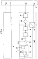
- the signal converter 70 in the form of a microcontroller according to FIG. 3 in a multi-channel registration device using the same reference numerals as in FIG. 1 for the same means as a common signal converter 70 for a plurality of registration channels 1 to n.
- the signal converter 70 has exactly n inputs 711 to 71n and n outputs 721 to 72n, which are each assigned in pairs to one of the registration channels 1 to n.
- the high positioning accuracy is achieved in particular in that the capture range of the pulse width modulator 40 can be designed such that, on the one hand, even small absolute non-zero control deviations 300 cause a large change in the duty cycle of the pulse width modulated control signal 400, which corresponds to a high internal gain and thus a precise positionability of the stylus 10 in accordance with the measurement signal 100, and on the other hand limits of the capture range can be dimensioned such that reaching a limit value causes the maximum travel speed of the stylus 10.
- the catch range of the pulse width modulator 40 is understood to mean the range of values of the control deviation 300 which can be transferred into a proportional pulse duty factor.
- the pulse-width-modulated control signal 400 permanently has the logic state ONE, with the stylus 10 having moved in its first direction of movement at maximum travel speed until the control deviation 300 falls below the upper limit of the capture range. If the control deviation 300 falls below the lower limit of the capture range, the pulse-width-modulated control signal 400 permanently has the logic state ZERO, the pen 10 at its maximum travel speed in its second Direction of movement is moved until the control deviation 300 exceeds the lower limit of the capture range.
- the capture range of the pulse width modulator 40 is normalized in FIG. 2 by the limit values 1 "and -1 "of the amplitude scale.
- an optocoupler 60 for galvanic isolation of the simplest type is suitable for transmitting continuous wave signals, such as those emitted by the pulse width modulator 40 when the control range 300 leaves the capture range.
- continuous wave signals such as those emitted by the pulse width modulator 40 when the control range 300 leaves the capture range.
Landscapes
- Physics & Mathematics (AREA)
- General Physics & Mathematics (AREA)
- Recording Measured Values (AREA)
- Control Of Position Or Direction (AREA)
Applications Claiming Priority (2)
| Application Number | Priority Date | Filing Date | Title |
|---|---|---|---|
| DE19541132 | 1995-10-27 | ||
| DE19541132A DE19541132A1 (de) | 1995-10-27 | 1995-10-27 | Anordnung zum Positionieren eines Schreibstiftes in einer Registriereinrichtung |
Publications (2)
| Publication Number | Publication Date |
|---|---|
| EP0770852A1 true EP0770852A1 (fr) | 1997-05-02 |
| EP0770852B1 EP0770852B1 (fr) | 1999-01-07 |
Family
ID=7776615
Family Applications (1)
| Application Number | Title | Priority Date | Filing Date |
|---|---|---|---|
| EP96250241A Expired - Lifetime EP0770852B1 (fr) | 1995-10-27 | 1996-10-24 | Agencement pour positionner un élément d'écriture dans un appareil d'enregistrement |
Country Status (3)
| Country | Link |
|---|---|
| EP (1) | EP0770852B1 (fr) |
| JP (1) | JPH09145422A (fr) |
| DE (2) | DE19541132A1 (fr) |
Families Citing this family (2)
| Publication number | Priority date | Publication date | Assignee | Title |
|---|---|---|---|---|
| DE19820273A1 (de) * | 1998-05-07 | 1999-11-18 | Kurt Sinske | Verfahren und Vorrichtung zur Positionierung eines Gegenstandes |
| US6909075B2 (en) | 2002-09-20 | 2005-06-21 | Leroy Eclat Ag | Method and apparatus for heat treatment of raw materials |
Citations (4)
| Publication number | Priority date | Publication date | Assignee | Title |
|---|---|---|---|---|
| US4318110A (en) * | 1979-10-04 | 1982-03-02 | Watanabe Sokki Kabushiki Kaisha | Multi-channel recording instrument |
| US4368411A (en) * | 1981-07-13 | 1983-01-11 | Kollmorgen Technologies Corporation | Control system for electric motor |
| EP0078367A2 (fr) | 1981-09-30 | 1983-05-11 | The Foxboro Company | Indicateur/enregistreur d'un processus industriel comprenant un actionnement à moteur du type pas à pas |
| DE3607249A1 (de) | 1985-11-08 | 1987-05-14 | Yokogawa Hokushin Electric | Selbstabgleichender stiftschreiber |
Family Cites Families (1)
| Publication number | Priority date | Publication date | Assignee | Title |
|---|---|---|---|---|
| US4888710A (en) * | 1987-12-11 | 1989-12-19 | Ametek, Inc. | Pen tip position detector |
-
1995
- 1995-10-27 DE DE19541132A patent/DE19541132A1/de not_active Withdrawn
-
1996
- 1996-10-24 EP EP96250241A patent/EP0770852B1/fr not_active Expired - Lifetime
- 1996-10-24 DE DE59601105T patent/DE59601105D1/de not_active Expired - Fee Related
- 1996-10-25 JP JP8301254A patent/JPH09145422A/ja active Pending
Patent Citations (4)
| Publication number | Priority date | Publication date | Assignee | Title |
|---|---|---|---|---|
| US4318110A (en) * | 1979-10-04 | 1982-03-02 | Watanabe Sokki Kabushiki Kaisha | Multi-channel recording instrument |
| US4368411A (en) * | 1981-07-13 | 1983-01-11 | Kollmorgen Technologies Corporation | Control system for electric motor |
| EP0078367A2 (fr) | 1981-09-30 | 1983-05-11 | The Foxboro Company | Indicateur/enregistreur d'un processus industriel comprenant un actionnement à moteur du type pas à pas |
| DE3607249A1 (de) | 1985-11-08 | 1987-05-14 | Yokogawa Hokushin Electric | Selbstabgleichender stiftschreiber |
Also Published As
| Publication number | Publication date |
|---|---|
| JPH09145422A (ja) | 1997-06-06 |
| EP0770852B1 (fr) | 1999-01-07 |
| DE19541132A1 (de) | 1997-04-30 |
| DE59601105D1 (de) | 1999-02-18 |
Similar Documents
| Publication | Publication Date | Title |
|---|---|---|
| DE3509714A1 (de) | Mitkopplungsschaltung und verfahren zum bilden derselben | |
| DE3305725C2 (fr) | ||
| DE3534595A1 (de) | Stromversorgung zum lichtbogenschweissen | |
| EP1118043B1 (fr) | Procede et circuit pour parametrer automatiquement un circuit de regulation de vitesse numerique rapide | |
| DE60225413T2 (de) | Motorsteuerverfahren und -vorrichtung | |
| DE2710049C2 (de) | Ultraschall-Zahnbehandlungsgerät | |
| EP0770853B1 (fr) | Procédé pour positionner un élément d'écriture dans un appareil d'enregistrement | |
| EP0179219A2 (fr) | Méthode et appareil pour produire une tension temporisée de commande de position | |
| EP1005147B1 (fr) | Méthode et circuit électrique pour déterminer le gain optimal de l'intégrateur d'un régulateur de vitesse | |
| EP0770852A1 (fr) | Agencement pour positionner un élément d'écriture dans un appareil d'enregistrement | |
| DE2509343C3 (de) | Einrichtung zur Regelung der Drehzahl von umlaufenden Maschinen | |
| DE3126277A1 (de) | "drehzahlsteuerschaltung" | |
| DE2332735C2 (de) | Steuereinrichtung für ein einstellbares Element | |
| EP1053588B1 (fr) | Procedes pour etablir des instructions de reglage pour redresseurs | |
| DE19909812A1 (de) | Positionssteuerung | |
| DE3830100A1 (de) | Verfahren zur optimierung der abstimmung eines senders und anordnung zum durchfuehren des verfahrens | |
| DE2209207A1 (de) | Vorrichtung zum Umsetzen digitaler Zahlenwerte in entsprechende Analogwerte | |
| DE3609731C2 (de) | Verfahren zur Regelung der Ausgangsspannung eines Schaltreglers sowie Anordnung hierzu | |
| DE19642443C2 (de) | Verfahren zur Regelung einer Regelgröße | |
| DE2742079B2 (de) | Antriebsanordnung zur Positionierung einer Antriebswelle | |
| DE3146764C2 (de) | Drehzahlregeleinrichtung für Freistrahl-Wasserturbinen | |
| DE2833540A1 (de) | Einrichtung zum regeln der geschwindigkeit eines positionierers fuer die schreib-/lesekoepfe eines magnetplattenspeichers | |
| DE2345416A1 (de) | Verfahren und vorrichtung zur schlupffreien nachlaufsteuerung von schrittmotoren | |
| DE2843689C2 (de) | Adaptiver Stromregler für Stromrichterantriebe | |
| DE2751276C2 (fr) |
Legal Events
| Date | Code | Title | Description |
|---|---|---|---|
| PUAI | Public reference made under article 153(3) epc to a published international application that has entered the european phase |
Free format text: ORIGINAL CODE: 0009012 |
|
| AK | Designated contracting states |
Kind code of ref document: A1 Designated state(s): DE DK GB GR LU PT |
|
| 17P | Request for examination filed |
Effective date: 19970424 |
|
| 17Q | First examination report despatched |
Effective date: 19970718 |
|
| GRAG | Despatch of communication of intention to grant |
Free format text: ORIGINAL CODE: EPIDOS AGRA |
|
| GRAG | Despatch of communication of intention to grant |
Free format text: ORIGINAL CODE: EPIDOS AGRA |
|
| GRAH | Despatch of communication of intention to grant a patent |
Free format text: ORIGINAL CODE: EPIDOS IGRA |
|
| GRAH | Despatch of communication of intention to grant a patent |
Free format text: ORIGINAL CODE: EPIDOS IGRA |
|
| GRAA | (expected) grant |
Free format text: ORIGINAL CODE: 0009210 |
|
| RAP1 | Party data changed (applicant data changed or rights of an application transferred) |
Owner name: HARTMANN & BRAUN GMBH & CO. KG |
|
| AK | Designated contracting states |
Kind code of ref document: B1 Designated state(s): DE DK GB GR LU PT |
|
| PG25 | Lapsed in a contracting state [announced via postgrant information from national office to epo] |
Ref country code: GR Free format text: LAPSE BECAUSE OF NON-PAYMENT OF DUE FEES Effective date: 19990107 |
|
| GBT | Gb: translation of ep patent filed (gb section 77(6)(a)/1977) |
Effective date: 19990108 |
|
| REF | Corresponds to: |
Ref document number: 59601105 Country of ref document: DE Date of ref document: 19990218 |
|
| PG25 | Lapsed in a contracting state [announced via postgrant information from national office to epo] |
Ref country code: PT Free format text: LAPSE BECAUSE OF FAILURE TO SUBMIT A TRANSLATION OF THE DESCRIPTION OR TO PAY THE FEE WITHIN THE PRESCRIBED TIME-LIMIT Effective date: 19990407 Ref country code: DK Free format text: LAPSE BECAUSE OF FAILURE TO SUBMIT A TRANSLATION OF THE DESCRIPTION OR TO PAY THE FEE WITHIN THE PRESCRIBED TIME-LIMIT Effective date: 19990407 |
|
| PG25 | Lapsed in a contracting state [announced via postgrant information from national office to epo] |
Ref country code: LU Free format text: LAPSE BECAUSE OF NON-PAYMENT OF DUE FEES Effective date: 19991024 |
|
| PLBE | No opposition filed within time limit |
Free format text: ORIGINAL CODE: 0009261 |
|
| STAA | Information on the status of an ep patent application or granted ep patent |
Free format text: STATUS: NO OPPOSITION FILED WITHIN TIME LIMIT |
|
| 26N | No opposition filed | ||
| REG | Reference to a national code |
Ref country code: GB Ref legal event code: IF02 |
|
| PGFP | Annual fee paid to national office [announced via postgrant information from national office to epo] |
Ref country code: GB Payment date: 20030929 Year of fee payment: 8 |
|
| PGFP | Annual fee paid to national office [announced via postgrant information from national office to epo] |
Ref country code: DE Payment date: 20031010 Year of fee payment: 8 |
|
| PG25 | Lapsed in a contracting state [announced via postgrant information from national office to epo] |
Ref country code: GB Free format text: LAPSE BECAUSE OF NON-PAYMENT OF DUE FEES Effective date: 20041024 |
|
| PG25 | Lapsed in a contracting state [announced via postgrant information from national office to epo] |
Ref country code: DE Free format text: LAPSE BECAUSE OF NON-PAYMENT OF DUE FEES Effective date: 20050503 |
|
| GBPC | Gb: european patent ceased through non-payment of renewal fee |
Effective date: 20041024 |