EP0770870B1 - Vanne et son utilisation - Google Patents
Vanne et son utilisation Download PDFInfo
- Publication number
- EP0770870B1 EP0770870B1 EP96117153A EP96117153A EP0770870B1 EP 0770870 B1 EP0770870 B1 EP 0770870B1 EP 96117153 A EP96117153 A EP 96117153A EP 96117153 A EP96117153 A EP 96117153A EP 0770870 B1 EP0770870 B1 EP 0770870B1
- Authority
- EP
- European Patent Office
- Prior art keywords
- valve
- gas
- pulsed
- ionization
- valve according
- Prior art date
- Legal status (The legal status is an assumption and is not a legal conclusion. Google has not performed a legal analysis and makes no representation as to the accuracy of the status listed.)
- Expired - Lifetime
Links
- OKTJSMMVPCPJKN-UHFFFAOYSA-N Carbon Chemical compound [C] OKTJSMMVPCPJKN-UHFFFAOYSA-N 0.000 abstract description 6
- 229910002804 graphite Inorganic materials 0.000 abstract description 3
- 239000010439 graphite Substances 0.000 abstract description 3
- 238000004817 gas chromatography Methods 0.000 description 81
- 239000007789 gas Substances 0.000 description 66
- 238000001561 resonance enhanced multiphoton ionisation spectroscopy Methods 0.000 description 26
- 150000002500 ions Chemical class 0.000 description 19
- 238000001816 cooling Methods 0.000 description 17
- URLKBWYHVLBVBO-UHFFFAOYSA-N Para-Xylene Chemical group CC1=CC=C(C)C=C1 URLKBWYHVLBVBO-UHFFFAOYSA-N 0.000 description 16
- 230000008878 coupling Effects 0.000 description 15
- 238000010168 coupling process Methods 0.000 description 15
- 238000005859 coupling reaction Methods 0.000 description 15
- 230000035945 sensitivity Effects 0.000 description 13
- 238000004611 spectroscopical analysis Methods 0.000 description 13
- 239000000126 substance Substances 0.000 description 13
- 239000012159 carrier gas Substances 0.000 description 12
- 238000002290 gas chromatography-mass spectrometry Methods 0.000 description 12
- 230000005284 excitation Effects 0.000 description 10
- 238000001228 spectrum Methods 0.000 description 10
- 238000001269 time-of-flight mass spectrometry Methods 0.000 description 10
- 238000004458 analytical method Methods 0.000 description 9
- IVSZLXZYQVIEFR-UHFFFAOYSA-N 1,3-Dimethylbenzene Natural products CC1=CC=CC(C)=C1 IVSZLXZYQVIEFR-UHFFFAOYSA-N 0.000 description 8
- 238000001514 detection method Methods 0.000 description 7
- 238000000870 ultraviolet spectroscopy Methods 0.000 description 7
- UHOVQNZJYSORNB-UHFFFAOYSA-N Benzene Chemical compound C1=CC=CC=C1 UHOVQNZJYSORNB-UHFFFAOYSA-N 0.000 description 6
- YXFVVABEGXRONW-UHFFFAOYSA-N Toluene Chemical compound CC1=CC=CC=C1 YXFVVABEGXRONW-UHFFFAOYSA-N 0.000 description 6
- 230000014759 maintenance of location Effects 0.000 description 6
- 229920003223 poly(pyromellitimide-1,4-diphenyl ether) Polymers 0.000 description 6
- 238000000752 ionisation method Methods 0.000 description 5
- YNQLUTRBYVCPMQ-UHFFFAOYSA-N Ethylbenzene Chemical compound CCC1=CC=CC=C1 YNQLUTRBYVCPMQ-UHFFFAOYSA-N 0.000 description 4
- 239000004809 Teflon Substances 0.000 description 4
- 229920006362 Teflon® Polymers 0.000 description 4
- 230000000694 effects Effects 0.000 description 4
- 230000007613 environmental effect Effects 0.000 description 4
- 238000004949 mass spectrometry Methods 0.000 description 4
- 230000007935 neutral effect Effects 0.000 description 4
- CTQNGGLPUBDAKN-UHFFFAOYSA-N o-dimethylbenzene Natural products CC1=CC=CC=C1C CTQNGGLPUBDAKN-UHFFFAOYSA-N 0.000 description 4
- 238000012216 screening Methods 0.000 description 4
- 238000000926 separation method Methods 0.000 description 4
- 229910000831 Steel Inorganic materials 0.000 description 3
- 230000005494 condensation Effects 0.000 description 3
- 239000003480 eluent Substances 0.000 description 3
- 238000010438 heat treatment Methods 0.000 description 3
- 239000007788 liquid Substances 0.000 description 3
- 230000003446 memory effect Effects 0.000 description 3
- 238000000034 method Methods 0.000 description 3
- 238000005457 optimization Methods 0.000 description 3
- 230000009467 reduction Effects 0.000 description 3
- 238000007789 sealing Methods 0.000 description 3
- 241000894007 species Species 0.000 description 3
- 239000010959 steel Substances 0.000 description 3
- KZNJSFHJUQDYHE-UHFFFAOYSA-N 1-methylanthracene Chemical class C1=CC=C2C=C3C(C)=CC=CC3=CC2=C1 KZNJSFHJUQDYHE-UHFFFAOYSA-N 0.000 description 2
- 229910001369 Brass Inorganic materials 0.000 description 2
- 238000010521 absorption reaction Methods 0.000 description 2
- 230000006978 adaptation Effects 0.000 description 2
- 150000004996 alkyl benzenes Chemical class 0.000 description 2
- XAGFODPZIPBFFR-UHFFFAOYSA-N aluminium Chemical compound [Al] XAGFODPZIPBFFR-UHFFFAOYSA-N 0.000 description 2
- 229910052782 aluminium Inorganic materials 0.000 description 2
- 150000004945 aromatic hydrocarbons Chemical class 0.000 description 2
- 239000010951 brass Substances 0.000 description 2
- 238000003965 capillary gas chromatography Methods 0.000 description 2
- 238000009833 condensation Methods 0.000 description 2
- 238000013461 design Methods 0.000 description 2
- 238000011161 development Methods 0.000 description 2
- TXCDCPKCNAJMEE-UHFFFAOYSA-N dibenzofuran Chemical compound C1=CC=C2C3=CC=CC=C3OC2=C1 TXCDCPKCNAJMEE-UHFFFAOYSA-N 0.000 description 2
- 150000002013 dioxins Chemical class 0.000 description 2
- 238000001506 fluorescence spectroscopy Methods 0.000 description 2
- 239000012634 fragment Substances 0.000 description 2
- 238000004128 high performance liquid chromatography Methods 0.000 description 2
- 238000003859 hyphenated technique Methods 0.000 description 2
- 238000001616 ion spectroscopy Methods 0.000 description 2
- 238000004989 laser desorption mass spectroscopy Methods 0.000 description 2
- 230000007257 malfunction Effects 0.000 description 2
- 239000000463 material Substances 0.000 description 2
- 238000005259 measurement Methods 0.000 description 2
- 239000000203 mixture Substances 0.000 description 2
- 229910052756 noble gas Inorganic materials 0.000 description 2
- 125000005575 polycyclic aromatic hydrocarbon group Chemical group 0.000 description 2
- 238000002360 preparation method Methods 0.000 description 2
- 238000005070 sampling Methods 0.000 description 2
- 230000002123 temporal effect Effects 0.000 description 2
- 238000001196 time-of-flight mass spectrum Methods 0.000 description 2
- 238000004454 trace mineral analysis Methods 0.000 description 2
- DSUXYILICHOCQS-UHFFFAOYSA-N 2-chloro-1,4-dioxine Chemical class ClC1=COC=CO1 DSUXYILICHOCQS-UHFFFAOYSA-N 0.000 description 1
- 238000004252 FT/ICR mass spectrometry Methods 0.000 description 1
- VYPSYNLAJGMNEJ-UHFFFAOYSA-N Silicium dioxide Chemical compound O=[Si]=O VYPSYNLAJGMNEJ-UHFFFAOYSA-N 0.000 description 1
- 238000000862 absorption spectrum Methods 0.000 description 1
- 239000012491 analyte Substances 0.000 description 1
- 238000013459 approach Methods 0.000 description 1
- 125000003118 aryl group Chemical group 0.000 description 1
- 230000006399 behavior Effects 0.000 description 1
- 150000001555 benzenes Chemical class 0.000 description 1
- 230000015572 biosynthetic process Effects 0.000 description 1
- 235000010290 biphenyl Nutrition 0.000 description 1
- 150000004074 biphenyls Chemical class 0.000 description 1
- 239000000919 ceramic Substances 0.000 description 1
- 238000012512 characterization method Methods 0.000 description 1
- 238000002485 combustion reaction Methods 0.000 description 1
- 230000001419 dependent effect Effects 0.000 description 1
- 238000009795 derivation Methods 0.000 description 1
- 238000009792 diffusion process Methods 0.000 description 1
- 238000010790 dilution Methods 0.000 description 1
- 239000012895 dilution Substances 0.000 description 1
- 230000005684 electric field Effects 0.000 description 1
- 230000005264 electron capture Effects 0.000 description 1
- 238000002474 experimental method Methods 0.000 description 1
- 230000002349 favourable effect Effects 0.000 description 1
- 239000012530 fluid Substances 0.000 description 1
- 238000001917 fluorescence detection Methods 0.000 description 1
- 239000000446 fuel Substances 0.000 description 1
- 230000006870 function Effects 0.000 description 1
- 239000011521 glass Substances 0.000 description 1
- 238000000227 grinding Methods 0.000 description 1
- 238000009499 grossing Methods 0.000 description 1
- 239000011261 inert gas Substances 0.000 description 1
- 238000001499 laser induced fluorescence spectroscopy Methods 0.000 description 1
- 238000000322 laser mass spectrometry Methods 0.000 description 1
- 238000011068 loading method Methods 0.000 description 1
- 238000012544 monitoring process Methods 0.000 description 1
- 238000013021 overheating Methods 0.000 description 1
- NFBOHOGPQUYFRF-UHFFFAOYSA-N oxanthrene Chemical compound C1=CC=C2OC3=CC=CC=C3OC2=C1 NFBOHOGPQUYFRF-UHFFFAOYSA-N 0.000 description 1
- -1 polycyclic aromatic compounds Chemical class 0.000 description 1
- 230000002040 relaxant effect Effects 0.000 description 1
- 125000006850 spacer group Chemical group 0.000 description 1
- 230000003595 spectral effect Effects 0.000 description 1
- 229910001220 stainless steel Inorganic materials 0.000 description 1
- 239000010935 stainless steel Substances 0.000 description 1
- 230000003068 static effect Effects 0.000 description 1
- 238000012360 testing method Methods 0.000 description 1
- 238000012546 transfer Methods 0.000 description 1
- 238000012929 ultra trace analysis Methods 0.000 description 1
Images






Classifications
-
- H—ELECTRICITY
- H01—ELECTRIC ELEMENTS
- H01J—ELECTRIC DISCHARGE TUBES OR DISCHARGE LAMPS
- H01J49/00—Particle spectrometers or separator tubes
- H01J49/02—Details
- H01J49/04—Arrangements for introducing or extracting samples to be analysed, e.g. vacuum locks; Arrangements for external adjustment of electron- or ion-optical components
- H01J49/0422—Arrangements for introducing or extracting samples to be analysed, e.g. vacuum locks; Arrangements for external adjustment of electron- or ion-optical components for gaseous samples
-
- G—PHYSICS
- G01—MEASURING; TESTING
- G01N—INVESTIGATING OR ANALYSING MATERIALS BY DETERMINING THEIR CHEMICAL OR PHYSICAL PROPERTIES
- G01N30/00—Investigating or analysing materials by separation into components using adsorption, absorption or similar phenomena or using ion-exchange, e.g. chromatography or field flow fractionation
- G01N30/02—Column chromatography
- G01N30/04—Preparation or injection of sample to be analysed
- G01N30/16—Injection
- G01N30/20—Injection using a sampling valve
-
- H—ELECTRICITY
- H01—ELECTRIC ELEMENTS
- H01J—ELECTRIC DISCHARGE TUBES OR DISCHARGE LAMPS
- H01J49/00—Particle spectrometers or separator tubes
- H01J49/02—Details
- H01J49/04—Arrangements for introducing or extracting samples to be analysed, e.g. vacuum locks; Arrangements for external adjustment of electron- or ion-optical components
- H01J49/0495—Vacuum locks; Valves
-
- G—PHYSICS
- G01—MEASURING; TESTING
- G01N—INVESTIGATING OR ANALYSING MATERIALS BY DETERMINING THEIR CHEMICAL OR PHYSICAL PROPERTIES
- G01N30/00—Investigating or analysing materials by separation into components using adsorption, absorption or similar phenomena or using ion-exchange, e.g. chromatography or field flow fractionation
- G01N30/02—Column chromatography
- G01N30/62—Detectors specially adapted therefor
- G01N30/72—Mass spectrometers
- G01N30/7206—Mass spectrometers interfaced to gas chromatograph
Definitions
- the invention relates to a valve according to the preamble of claim 1 as it is known from US-A-5224510 and its use.
- GC-MS Gas chromatography mass spectrometry
- Effective gas inlet In early experiments, the end of the GC capillary was used as a continuous effective gas inlet in a vacuum, or also in a gas cell, such as a kind of proportional counter tube / 1 /.
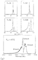
- the ions are generated by resonance-enhanced multiphoton ionization (REMPI) / 2 / (see FIG. 1). Since the first photon is absorbed on a molecule-specific basis due to its wavelength, this ionization method is very selective ( Figure 1). So to speak, UV spectroscopy is included in the ionization process.
- REMPI resonance-enhanced multiphoton ionization
- Another working group / 3 / ended the GC capillary directly in the ion source of a time-of-flight mass spectrometer, using an excimer laser that could not be tuned in wavelength for the ionization.
- this arrangement - effective entry into ion sources of time-of-flight mass analyzers - is also suitable for REMPI / 4,5,6 /.
- the sensitivity could be increased considerably (200-20ng) / 9 /.
- the continuous supersonic jet from a GC capillary was used to separate the carrier gas and the molecules to be specified (different spatial behavior) in order to then use non-selective ionization methods and quadrupole mass spectrometers to detect / 10 /.
- Disadvantages of continuous supersonic jets are either high gas generation and thus high demands on the vacuum system or backflow into the capillary with a reduction in the GC resolution.
- a continuous gas inlet combined with a pulsed ionization method - such as REMPI - leads to an unfavorable ratio of sample gas pulse length to ionization pulse length, and thus to a loss in sensitivity.
- valve into which a gas chromatography (GC) capillary opens, which is used to generate a molecular supersonic beam in a vacuum vessel, thereby coupling the GC to secondary trace analyzers, in particular mass spectrometers, fluorescence cells and ionization measuring cells, which realizes one Includes valve head with the end of a movable valve lifter and a cap with a nozzle hole.
- the tip of the valve lifter 1 is shaped so that it can periodically open and close the nozzle hole, that at the same time it clears the path between the nozzle hole and the tip of the GC capillary column 6 during the opening phase, and that it seals against the rest of the valve lifter and the valve interior is.
- the end of the GC capillary is guided so that it directly reaches the valve tappet tip and that it is sealed against the interior between valve tappet guide 2 and cap 3, and between valve tappet guide 2 and valve tappet 1 , in such a way that the dead volume between and around GC Capillary column end, valve stem tip and nozzle hole is as small as possible.
- the valve head consisting of capillary column end 6, valve tappet end 1 , nozzle hole 7 and surrounding seals 4, 5, 8, guides and holders can be heated to temperatures suitable for GC operation. Only the carrier gas from the GC capillary column and no additional carrier gas is used to form a pulsed supersonic jet.
- the thermal decoupling of the valve head and valve drive is achieved by spatial separation and selective heating of the valve head and cooling of the valve drive.
- the average opening time - pulse length x opening frequency - of the valve is matched to the gas flow of the GC.
- the opening time and pressure drop between the inside of the valve and the vacuum vessel are optimized in such a way that effective molecular cooling is achieved in the supersonic jet and high-resolution UV spectroscopy and thus high-resolution resonant multiphoton ionization (REMPI) are possible.
- the geometric dimensions, in particular the diameter of the valve head are small enough to be integrated into the ion optics of a time-of-flight mass spectrometer.
- a valve combined with resonant multiphoton ionization can be operated in such a way that, from pulsed excitation light sources, in particular lasers, with several very quickly switchable wavelengths and high pulse repetition rate, light is coupled into the GC supersonic beam in such a way that a substance or a substance can be selectively selected Substance class is excited that for each of these wavelengths a separate time-shifted time-of-flight mass spectrum is recorded, and that a GC spectrum or even a single GC peak is used to switch between these wavelengths.
- pulsed excitation light sources in particular lasers, with several very quickly switchable wavelengths and high pulse repetition rate
- valve head In Figure 3a, an embodiment of the valve head is shown according to the above claims.
- the entire valve including valve drive is shown in Figure 3b.
- the valve head consists of a cap 3, the guide part 2 for the movable plunger 1, the coupling (seal) 9 for the GC column 6.
- the cap 3 and guide part 2 are screwed together.
- the bore in the guide part 2 in which the tappet 1 is guided is made to fit the tappet 1 in order to provide a surface seal of the valve head space against the valve train 11.
- a further sealing effect is achieved by the insert 4 .
- In the middle of the bottom of the cap 3 there is a cup-shaped depression with a diameter of 0.3-1.2 mm and a depth of approx. 1 mm on the high pressure side.
- the conical tip of the plunger 1 which can be made of different materials (eg Vespel, aluminum, brass, Teflon) seals against the upper edge of the cup-shaped depression (edge seal).
- the edge of the cup-shaped countersink can be lowered conically to enable a surface seal with the plunger.
- the nozzle hole 7 In the bottom of the cup-shaped depression there is the nozzle hole 7 , for example with a diameter of 0.1 mm to 0.8 mm and a length of 0.1 to 1 mm.
- the volume of the cup-shaped depression is coupled to the vacuum side via this nozzle hole 7 .
- valve When the valve is operating as a coupling element between gas chromatography and, for example, resonant laser ionization in the supersonic molecular beam, the valve is operated periodically with the highest possible repetition frequency, for example 20 Hz. Opening times between 100 and 200 ⁇ s can be achieved with solenoid drives of the valve tappet.
- a disk-shaped insert 4 made of, for example, Vespel, steel, Teflon or glass.
- a groove is radially milled into its base, the inside dimensions of which correspond exactly to the outside dimensions of the capillary column.
- This Vespel insert 4 serves as a spacer between 2 and 3, as a guide for the end of the capillary column 6 and as a seal of the end of the capillary column against the gap between the plunger 1 and its guide 2.
- the end of the capillary column 6 is also made of a graphite micro seal 8 and a screw cap 9 sealed against the vacuum.
- the arrangement of the capillary column end, valve tappet tip and central opening in the Vespel insert ensures a minimal dead volume in front of the capillary end, which can be emptied very quickly via the nozzle hole if the movable tappet pulse-free clears the nozzle hole and the path between the nozzle hole and the capillary end.
- the relaxing gas is the GC carrier gas, in which the sample substances are dissolved and arrive at the end of the capillary column according to their retention times.
- FIG. 3b shows an embodiment in which a spatial separation of the valve head and a solenoid valve drive 11 was achieved by extending the valve tappet 1 and its guide 2 .
- the further course of the plunger 1 in the valve drive 11 is not shown.
- the valve head 3 can be heated by the heater 5 in order to avoid the condensation of volatile substances. If this heating causes the temperature of the solenoid valve train to become too high, it can be cooled by cooling 12 .
- By separating the valve head 3 and valve drive 11 By separating the valve head 3 and valve drive 11 , overheating of the valve drive 11 and associated malfunctions are avoided.
- Such a GC coupling with a pulsed supersonic jet valve has excellent properties, in particular for the combination with resonant multiphoton ionization (REMPI) and time-of-flight mass spectrometry.
- REMPI resonant multiphoton ionization
- the short gas pulses allow the detection of a high proportion of GC gas using pulsed ionization methods.
- FIG. 4 shows the embodiment of an overall system in which the pulsed GC supersonic jet valve is shown according to Figure 3 for coupling GC, REMPI and time-of-flight mass spectrometry is used.
- the valve is filled with GC carrier gas via a gas chromatograph and a heatable supply line loaded. This relaxes in a fore-vacuum system while cooling the inner one Degrees of freedom of the sample molecules dissolved in it.
- a skimmer serves as a pressure reduction stage and for Formation of a narrow, pulsed molecular beam. This crosses the ion source consisting of axially attached screens with central holes for the removal of ions. These become species-selective formed by resonant multiphoton ionization (REMPI), transverse to the molecular beam with subtracted from a static electric field and in a reflectron time-of-flight mass analyzer proven.
- REMPI resonant multiphoton ionization
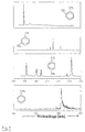
- FIG. 6a shows the gas chromatogram of a gasoline fuel that is used with the GC supersonic jet valve, a laser wavelength specific for aromatics but unselective among aromatics and was recorded synchronously with four masses.
- the mass 106 shows in Gas chromatogram of ethylbenzene, meta-, ortho- and para-xylene. Thereby meta- and para-xylene not separated from the column used. A smoothing of the GC pulses is practically not noticeable.
- Figure 6b the molecular group of mass 106 is once conventional Gas chromatography, and once via GC supersonic beam REMPI with a laser wavelength of 266 nm, as shown in Figure 6a. In both cases, a capillary with identical Parameters used.
- FIGS. 7 and 8 are intended to demonstrate how the combination of the GC supersonic jet valve is used with REMPI the problem of missing isomer selectivity of the GC - see FIG. 6: meta and para-xylene - can be dissolved without chemical pre-separation.
- the laser light source from 266nm (unselective, Figure 6a) tuned to 272.3 nm. With this wavelength is now under the mentioned four isomeric molecules of mass 106 only para-xylene highly selectively excited. This prove the REMPI wavelength spectra in Figure 7. These spectra owe their spectral sharpness and thus selectivity of molecular cooling in the supersonic jet. Without this cooling one would be such isomer separation is absolutely not possible. Similar selective spectra could be found for dichlorinated dioxins and biphenyls or all polychlorinated benzenes are shown / 15 /.
- FIG. 8 shows a gas chromatogram with an aromatic non-selective one REMPI detection shown at a laser wavelength of 266nm (detail from Figure 6).
- figure 8 is a gas chromatogram of the same sample (section of the GC retention time itself), but with para-xylene-selective detection at the laser wavelength of 272.3 nm. The high selectivity only for para-xylene can be clearly determined.
- the sensitivity was tested in FIG. For 500 fg toluene, the signal-to-noise ratio was still 6. An optimization of the Ionization efficiency that has not been done yet can still improve lead at least one order of magnitude. This also makes the sensitivity range more conventional High-resolution capillary GC-MS devices reached.
Landscapes
- Chemical & Material Sciences (AREA)
- Analytical Chemistry (AREA)
- General Health & Medical Sciences (AREA)
- Life Sciences & Earth Sciences (AREA)
- Health & Medical Sciences (AREA)
- Biochemistry (AREA)
- Physics & Mathematics (AREA)
- General Physics & Mathematics (AREA)
- Immunology (AREA)
- Pathology (AREA)
- Other Investigation Or Analysis Of Materials By Electrical Means (AREA)
- External Artificial Organs (AREA)
- Electron Tubes For Measurement (AREA)
- Magnetically Actuated Valves (AREA)
Claims (8)
- Vanne pulsée formée d'un capuchon, d'un poussoir mobile, d'une buse et d'une alimentation en gaz, d'un organe de guidage du poussoir mobile, d'une cavité au-dessus de l'orifice de buse et d'un insert en forme de rondelle,
caractérisée en ce que
l'insert en forme de rondelle (4) est réalisé pour obtenir un volume mort minimum et il comporte une rainure comme moyen de guidage pour l'alimentation en gaz (6) et un perçage central correspondant au diamètre du poussoir mobile, les dimensions intérieures de la rainure correspondant exactement aux dimensions extérieures de l'alimentation en gaz (6). - Vanne pulsée selon la revendication 1,
caractérisée en ce que
la pointe du poussoir mobile (1) est conique et fait l'étanchéité avec le bord supérieur de la cavité au-dessus de l'orifice de buse (7). - Vanne pulsée selon la revendication 1 ou 2,
caractérisée en ce que
le bord de la cavité est réduit suivant une forme conique. - Vanne pulsée selon l'une quelconque des revendications 1 à 3,
caractérisée par
une extraction d'échantillon (6a). - Vanne pulsée selon l'une quelconque des revendications 1 à 4,
caractérisée par
des joints (8, 8a) pour l'alimentation en gaz (6) et l'extraction d'échantillon (6a). - Vanne pulsée selon l'une quelconque des revendications 1 à 5,
caractérisée par
un moyen de chauffage (5). - Vanne pulsée selon l'une quelconque des revendications 1 à 6,
caractérisée par
un moyen de refroidissement (12) pour le moteur (11) de la vanne. - Application de la vanne pulsée selon l'une quelconque des revendications 1 à 7 pour injecter une veine de gaz dans un appareil d'analyse secondaire de traces.
Applications Claiming Priority (2)
| Application Number | Priority Date | Filing Date | Title |
|---|---|---|---|
| DE19539589 | 1995-10-25 | ||
| DE19539589A DE19539589C2 (de) | 1995-10-25 | 1995-10-25 | Gepulstes Ventil für die Kopplung einer Gaschromatographie-Kapillare an ein sekundäres Spurenanalysegerät mittels eines Überschallstrahles |
Publications (3)
| Publication Number | Publication Date |
|---|---|
| EP0770870A2 EP0770870A2 (fr) | 1997-05-02 |
| EP0770870A3 EP0770870A3 (fr) | 1998-01-14 |
| EP0770870B1 true EP0770870B1 (fr) | 2001-08-01 |
Family
ID=7775653
Family Applications (1)
| Application Number | Title | Priority Date | Filing Date |
|---|---|---|---|
| EP96117153A Expired - Lifetime EP0770870B1 (fr) | 1995-10-25 | 1996-10-25 | Vanne et son utilisation |
Country Status (4)
| Country | Link |
|---|---|
| EP (1) | EP0770870B1 (fr) |
| AT (1) | ATE203823T1 (fr) |
| DE (2) | DE19539589C2 (fr) |
| DK (1) | DK0770870T3 (fr) |
Families Citing this family (7)
| Publication number | Priority date | Publication date | Assignee | Title |
|---|---|---|---|---|
| DE19754161C2 (de) * | 1997-12-06 | 1999-11-25 | Gsf Forschungszentrum Umwelt | Verfahren zum Nachweis von Substanzen und Substanzklassen |
| DE19822672B4 (de) | 1998-05-20 | 2005-11-10 | GSF - Forschungszentrum für Umwelt und Gesundheit GmbH | Verfahren und Vorrichtung zur Erzeugung eines gerichteten Gasstrahls |
| DE19822674A1 (de) * | 1998-05-20 | 1999-12-09 | Gsf Forschungszentrum Umwelt | Gaseinlaß für eine Ionenquelle |
| US6355929B1 (en) * | 1998-10-16 | 2002-03-12 | Siemens Energy & Automation, Inc. | Method for forming a seat in a pulsed sampling valve |
| DE10014962A1 (de) | 2000-03-25 | 2001-10-04 | Gsf Forschungszentrum Umwelt | Pulsbares Kapillarventil |
| JP5784825B2 (ja) | 2011-05-20 | 2015-09-24 | パーデュー・リサーチ・ファウンデーションPurdue Research Foundation | 試料を分析するためのシステムおよび方法 |
| DE102018216623A1 (de) | 2018-09-27 | 2020-04-02 | Carl Zeiss Smt Gmbh | Massenspektrometer und Verfahren zur massenspektrometrischen Analyse eines Gases |
Family Cites Families (3)
| Publication number | Priority date | Publication date | Assignee | Title |
|---|---|---|---|---|
| DE2942386C2 (de) * | 1979-10-19 | 1984-01-12 | Ulrich Dr. 8000 München Boesl | Ionenquelle |
| US5178767A (en) * | 1989-02-27 | 1993-01-12 | Hewlett-Packard Company | Axially-driven valve controlled trapping assembly |
| ATE109281T1 (de) * | 1989-11-08 | 1994-08-15 | Ciba Geigy Ag | Ventil. |
-
1995
- 1995-10-25 DE DE19539589A patent/DE19539589C2/de not_active Expired - Fee Related
-
1996
- 1996-10-25 EP EP96117153A patent/EP0770870B1/fr not_active Expired - Lifetime
- 1996-10-25 DK DK96117153T patent/DK0770870T3/da active
- 1996-10-25 DE DE59607407T patent/DE59607407D1/de not_active Expired - Fee Related
- 1996-10-25 AT AT96117153T patent/ATE203823T1/de not_active IP Right Cessation
Also Published As
| Publication number | Publication date |
|---|---|
| DE19539589A1 (de) | 1997-04-30 |
| EP0770870A3 (fr) | 1998-01-14 |
| EP0770870A2 (fr) | 1997-05-02 |
| ATE203823T1 (de) | 2001-08-15 |
| DE19539589C2 (de) | 1999-01-28 |
| DE59607407D1 (de) | 2001-09-06 |
| DK0770870T3 (da) | 2001-10-08 |
Similar Documents
| Publication | Publication Date | Title |
|---|---|---|
| JP2632668B2 (ja) | ガスクロマトグラフィー注入弁およびガスクロマトグラフィーシステム | |
| Schomburg et al. | Aspects of double-column gas chromatography with glass capillaries involving intermediate trapping | |
| DE69308349T2 (de) | Zeitliche Modulation eines Elektrosprays | |
| Rodriguez‐Cruz | Rapid analysis of controlled substances using desorption electrospray ionization mass spectrometry | |
| DE69205910T2 (de) | Thermisches Modulationseinlasssystem für Gaschromatographie. | |
| Mondello et al. | Comprehensive two-dimensional gas chromatography–mass spectrometry | |
| Motoyama et al. | Direct determination of bisphenol A and nonylphenol in river water by column‐switching semi‐microcolumn liquid chromatography/electrospray mass spectrometry | |
| DE102017011423B4 (de) | Verfahren und Vorrichtung für lsotopenverhältnis-Massenspektrometrie | |
| Zimmermann et al. | Three-dimensional trace analysis: combination of gas chromatography, supersonic beam UV spectroscopy and time-of-flight mass spectrometry | |
| Armitage et al. | The analysis of the Saltzman Collection of Peruvian dyes by high performance liquid chromatography and ambient ionisation mass spectrometry | |
| Zimmermann et al. | Hyphenation of gas chromatography and resonance‐enhanced laser mass spectrometry (REMPI‐TOFMS): A multidimensional analytical technique | |
| Duvivier et al. | Critical comparison of mass analyzers for forensic hair analysis by ambient ionization mass spectrometry | |
| Ford et al. | Thin‐layer chromatography/electrospray ionization triple‐quadrupole linear ion trap mass spectrometry system: Analysis of rhodamine dyes separated on reversed‐phase C8 plates | |
| DE19539589C2 (de) | Gepulstes Ventil für die Kopplung einer Gaschromatographie-Kapillare an ein sekundäres Spurenanalysegerät mittels eines Überschallstrahles | |
| US4536199A (en) | Gas chromatograph for reseparating a sampel into pure components | |
| Cavagnino et al. | Comprehensive two-dimensional gas chromatography using large sample volume injection for the determination of polynuclear aromatic hydrocarbons in complex matrices | |
| González‐Rodríguez et al. | Evaluation of low‐pressure gas chromatography linked to ion‐trap tandem mass spectrometry for the fast trace analysis of multiclass pesticide residues | |
| EP1994403B1 (fr) | Analyse de melanges de substances | |
| DE112005002632T5 (de) | Flüssigchromatograph | |
| Salvi et al. | Bulk analysis of volatiles in fluid inclusions | |
| Benavides et al. | Instrumental analysis of flavors and fragrances in food processing: Hyphenated techniques | |
| US4432225A (en) | Detection system for a gas chromatograph | |
| DE10125126A1 (de) | Integriertes miniaturisiertes chemisches Labor mit bildverarbeitender Erfassung einer Detektorfläche | |
| Elbert et al. | Off-line coupling of liquid chromatograph and mass spectrometer | |
| Roux et al. | Other instrumental approaches to fibre examination |
Legal Events
| Date | Code | Title | Description |
|---|---|---|---|
| PUAI | Public reference made under article 153(3) epc to a published international application that has entered the european phase |
Free format text: ORIGINAL CODE: 0009012 |
|
| AK | Designated contracting states |
Kind code of ref document: A2 Designated state(s): AT BE CH DE DK FR GB IE IT LI NL SE |
|
| PUAL | Search report despatched |
Free format text: ORIGINAL CODE: 0009013 |
|
| AK | Designated contracting states |
Kind code of ref document: A3 Designated state(s): AT BE CH DE DK FR GB IE IT LI NL SE |
|
| 17P | Request for examination filed |
Effective date: 19980131 |
|
| 17Q | First examination report despatched |
Effective date: 19990908 |
|
| GRAG | Despatch of communication of intention to grant |
Free format text: ORIGINAL CODE: EPIDOS AGRA |
|
| GRAG | Despatch of communication of intention to grant |
Free format text: ORIGINAL CODE: EPIDOS AGRA |
|
| GRAH | Despatch of communication of intention to grant a patent |
Free format text: ORIGINAL CODE: EPIDOS IGRA |
|
| ITF | It: translation for a ep patent filed | ||
| GRAH | Despatch of communication of intention to grant a patent |
Free format text: ORIGINAL CODE: EPIDOS IGRA |
|
| GRAA | (expected) grant |
Free format text: ORIGINAL CODE: 0009210 |
|
| AK | Designated contracting states |
Kind code of ref document: B1 Designated state(s): AT BE CH DE DK FR GB IE IT LI NL SE |
|
| REF | Corresponds to: |
Ref document number: 203823 Country of ref document: AT Date of ref document: 20010815 Kind code of ref document: T |
|
| REG | Reference to a national code |
Ref country code: CH Ref legal event code: EP |
|
| REG | Reference to a national code |
Ref country code: CH Ref legal event code: NV Representative=s name: ROTTMANN, ZIMMERMANN + PARTNER AG |
|
| REG | Reference to a national code |
Ref country code: IE Ref legal event code: FG4D Free format text: GERMAN |
|
| REF | Corresponds to: |
Ref document number: 59607407 Country of ref document: DE Date of ref document: 20010906 |
|
| REG | Reference to a national code |
Ref country code: DK Ref legal event code: T3 |
|
| ET | Fr: translation filed | ||
| REG | Reference to a national code |
Ref country code: GB Ref legal event code: IF02 |
|
| GBV | Gb: ep patent (uk) treated as always having been void in accordance with gb section 77(7)/1977 [no translation filed] |
Effective date: 20010801 |
|
| GBT | Gb: translation of ep patent filed (gb section 77(6)(a)/1977) |
Effective date: 20020206 |
|
| REG | Reference to a national code |
Ref country code: GB Ref legal event code: 710B Free format text: FOLLOWING A REQUEST UNDER RULE 110(4) OF THE RULES 1995 TO EXTEND THE PERIOD FOR FILING A TRANSLATION OF THE SPECIFICATION, A TRANSLATION HAS NOW BEEN FILED IN ACCORDANCE WITH SECTION 77(6)(A). THIS PATENT WAS ANNOUNCED AS VOID IN THE PATENTS AND DESIGNS JOURNAL DATED 30.01.2002. THE PATENT IS NOW REINSTATED WITH A GRANT DATE EFFECTIVE IN THE UK OF 01.08.2001. |
|
| PLBE | No opposition filed within time limit |
Free format text: ORIGINAL CODE: 0009261 |
|
| STAA | Information on the status of an ep patent application or granted ep patent |
Free format text: STATUS: NO OPPOSITION FILED WITHIN TIME LIMIT |
|
| 26N | No opposition filed | ||
| PGFP | Annual fee paid to national office [announced via postgrant information from national office to epo] |
Ref country code: GB Payment date: 20030811 Year of fee payment: 8 |
|
| PGFP | Annual fee paid to national office [announced via postgrant information from national office to epo] |
Ref country code: CH Payment date: 20030930 Year of fee payment: 8 |
|
| PGFP | Annual fee paid to national office [announced via postgrant information from national office to epo] |
Ref country code: DK Payment date: 20031003 Year of fee payment: 8 |
|
| PGFP | Annual fee paid to national office [announced via postgrant information from national office to epo] |
Ref country code: IE Payment date: 20031013 Year of fee payment: 8 |
|
| PGFP | Annual fee paid to national office [announced via postgrant information from national office to epo] |
Ref country code: SE Payment date: 20031017 Year of fee payment: 8 |
|
| PGFP | Annual fee paid to national office [announced via postgrant information from national office to epo] |
Ref country code: AT Payment date: 20031024 Year of fee payment: 8 |
|
| PGFP | Annual fee paid to national office [announced via postgrant information from national office to epo] |
Ref country code: BE Payment date: 20031029 Year of fee payment: 8 |
|
| PGFP | Annual fee paid to national office [announced via postgrant information from national office to epo] |
Ref country code: NL Payment date: 20031030 Year of fee payment: 8 Ref country code: FR Payment date: 20031030 Year of fee payment: 8 |
|
| PG25 | Lapsed in a contracting state [announced via postgrant information from national office to epo] |
Ref country code: IE Free format text: LAPSE BECAUSE OF NON-PAYMENT OF DUE FEES Effective date: 20041025 Ref country code: GB Free format text: LAPSE BECAUSE OF NON-PAYMENT OF DUE FEES Effective date: 20041025 Ref country code: AT Free format text: LAPSE BECAUSE OF NON-PAYMENT OF DUE FEES Effective date: 20041025 |
|
| PG25 | Lapsed in a contracting state [announced via postgrant information from national office to epo] |
Ref country code: SE Free format text: LAPSE BECAUSE OF NON-PAYMENT OF DUE FEES Effective date: 20041026 |
|
| PG25 | Lapsed in a contracting state [announced via postgrant information from national office to epo] |
Ref country code: LI Free format text: LAPSE BECAUSE OF NON-PAYMENT OF DUE FEES Effective date: 20041031 Ref country code: CH Free format text: LAPSE BECAUSE OF NON-PAYMENT OF DUE FEES Effective date: 20041031 Ref country code: BE Free format text: LAPSE BECAUSE OF NON-PAYMENT OF DUE FEES Effective date: 20041031 |
|
| PG25 | Lapsed in a contracting state [announced via postgrant information from national office to epo] |
Ref country code: DK Free format text: LAPSE BECAUSE OF NON-PAYMENT OF DUE FEES Effective date: 20041101 |
|
| BERE | Be: lapsed |
Owner name: *GSF-FORSCHUNGSZENTRUM FUR UMWELT UND GESUNDHEIT G Effective date: 20041031 |
|
| PG25 | Lapsed in a contracting state [announced via postgrant information from national office to epo] |
Ref country code: NL Free format text: LAPSE BECAUSE OF NON-PAYMENT OF DUE FEES Effective date: 20050501 |
|
| EUG | Se: european patent has lapsed | ||
| REG | Reference to a national code |
Ref country code: DK Ref legal event code: EBP |
|
| GBPC | Gb: european patent ceased through non-payment of renewal fee |
Effective date: 20041025 |
|
| REG | Reference to a national code |
Ref country code: CH Ref legal event code: PL |
|
| PG25 | Lapsed in a contracting state [announced via postgrant information from national office to epo] |
Ref country code: FR Free format text: LAPSE BECAUSE OF NON-PAYMENT OF DUE FEES Effective date: 20050630 |
|
| NLV4 | Nl: lapsed or anulled due to non-payment of the annual fee |
Effective date: 20050501 |
|
| REG | Reference to a national code |
Ref country code: IE Ref legal event code: MM4A |
|
| REG | Reference to a national code |
Ref country code: FR Ref legal event code: ST |
|
| PG25 | Lapsed in a contracting state [announced via postgrant information from national office to epo] |
Ref country code: IT Free format text: LAPSE BECAUSE OF NON-PAYMENT OF DUE FEES;WARNING: LAPSES OF ITALIAN PATENTS WITH EFFECTIVE DATE BEFORE 2007 MAY HAVE OCCURRED AT ANY TIME BEFORE 2007. THE CORRECT EFFECTIVE DATE MAY BE DIFFERENT FROM THE ONE RECORDED. Effective date: 20051025 |
|
| BERE | Be: lapsed |
Owner name: *GSF-FORSCHUNGSZENTRUM FUR UMWELT UND GESUNDHEIT G Effective date: 20041031 |
|
| PGFP | Annual fee paid to national office [announced via postgrant information from national office to epo] |
Ref country code: DE Payment date: 20080422 Year of fee payment: 12 |
|
| PG25 | Lapsed in a contracting state [announced via postgrant information from national office to epo] |
Ref country code: DE Free format text: LAPSE BECAUSE OF NON-PAYMENT OF DUE FEES Effective date: 20090501 |