EP0770880A2 - Means for testing the isolation of windings - Google Patents
Means for testing the isolation of windings Download PDFInfo
- Publication number
- EP0770880A2 EP0770880A2 EP96116439A EP96116439A EP0770880A2 EP 0770880 A2 EP0770880 A2 EP 0770880A2 EP 96116439 A EP96116439 A EP 96116439A EP 96116439 A EP96116439 A EP 96116439A EP 0770880 A2 EP0770880 A2 EP 0770880A2
- Authority
- EP
- European Patent Office
- Prior art keywords
- winding
- contact point
- wire
- insulated
- wound
- Prior art date
- Legal status (The legal status is an assumption and is not a legal conclusion. Google has not performed a legal analysis and makes no representation as to the accuracy of the status listed.)
- Withdrawn
Links
Images
Classifications
-
- G—PHYSICS
- G01—MEASURING; TESTING
- G01R—MEASURING ELECTRIC VARIABLES; MEASURING MAGNETIC VARIABLES
- G01R31/00—Arrangements for testing electric properties; Arrangements for locating electric faults; Arrangements for electrical testing characterised by what is being tested not provided for elsewhere
- G01R31/34—Testing dynamo-electric machines
- G01R31/346—Testing of armature or field windings
Definitions
- the invention relates to a device for determining insulation damage to insulated wires wound by means of a winding device, in particular enamel-insulated motor winding wires.
- an electronic switch in particular a high-resistance transistor switch
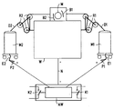
- the drawing shows a winding device W with a stator core or rotor core of an electric motor M held by it; enameled coil winding wires from a magazine M1 or M2 via guide rollers R1 or R2 and winding jaws B1 or B2 are used as insulated wires D1 or D2 e.g. wrapped in the grooves of the stator core or the rotor core of the electric motor M.
- Both the guide rollers R1 and R2 as well as the winding jaws B1 and B2 and the mounting of the electric motor M in the winding device W are usually designed in such a way that in the event of insulation damage, the wire which is then directly accessible in this area is also at the same potential as the mating contact part insulation-damaged adjacent wire or the winding device or the motor part.
- a DC potential + as a test voltage a DC potential + as a test voltage ; - preferably Approx. 12 - 30 volts between a stripped contact point P1 or P2 as a positive pole and a ground potential contact point N as a negative pole.
- a current will flow via the evaluation device AW due to the direct electrical contact between the bare wire D1 or D2 in the area of the insulation damage and the contacting part of the winding device W or a second insulation-damaged wire.
- the evaluation device AW which also supplies the test voltage +; -, can only be connected to the free winding ends E1 or E2, e.g. each time after changing the winding magazines M1 or M2, connectable.
- the device according to the invention detects both defects in the insulation, in particular in the enamel insulation of a coil winding wire, and damage during the winding process in a low-effort, in particular easily retrofittable manner, and consequently also damage caused by winding turns only in later use or body closures are recognizable in advance and thus avoidable.
Landscapes
- Physics & Mathematics (AREA)
- General Physics & Mathematics (AREA)
- Testing Of Short-Circuits, Discontinuities, Leakage, Or Incorrect Line Connections (AREA)
- Manufacture Of Motors, Generators (AREA)
Abstract
Description
Die Erfindung bezieht sich auf eine Vorrichtung zur Ermittlung von Isolationsschäden an mittels einer Wickelvorrichtung gewickelten isolierten Drähten, insbesondere lackisolierten Motorwicklungsdrähten gemäß Patentanspruch 1.The invention relates to a device for determining insulation damage to insulated wires wound by means of a winding device, in particular enamel-insulated motor winding wires.
Beispielsweise beim Einbringen von isolierten Spulenwicklungsdrähten, insbesondere lackisolierten Kupferdrähten, in Statorpakete bzw. Läuferkerne eines Elektromotors mittels an sich bekannter Wickelvorrichtungen (Flyer) besteht die Gefahr, daß die Isolation - wenn nicht schon bei Anlieferung schadhaft - durch die Einziehwerkzeuge bzw. Wickelbacken oder auch durch das in der Wickelvorrichtung aufgenommene zu bewickelnde Motorpaketteil beschädigt wird. Derartige Isolationsfehler werden bei üblichen Fertigungsverfahren erst bei Prüfung der fertiggewickelten Bauteile erkannt oder bleiben deswegen überhaupt unentdeckt, weil die isolationsgeschädigten Stellen von unbeschädigten isolierten Spulendrahtteilen bedeckt werden und somit nicht zu einem direkten unmittelbaren Windungsschluß zwischen zufällig benachbarten Schadstellen führen. Solche Isolationsschäden sind jedoch um so gefährlicher, da sie erst nach Betriebseinsatz des Motors, z.B. durch aufliegenden Abrieb der Bürsten eines Kommutatormotors, zum Windungsschluß zwischen dadurch überbrückten Isolationsfehlstellen bzw. zum Körperschluß mit Motormasseteilen zu einem Motorausfall führen können. Dies bedeutet insbesondere bei sicherheitsrelevanten Motoren, z.B. bei Antriebsmotoren für ABS-Systemen in Kraftfahrzeugen, ein erhebliches Qualitätsrisiko.For example, when inserting insulated coil winding wires, in particular enamelled copper wires, in stator packs or rotor cores of an electric motor by means of winding devices (flyers) known per se, there is a risk that the insulation - if not already defective upon delivery - will be caused by the pulling tools or winding jaws or by the motor package part to be wound which is accommodated in the winding device is damaged. Such insulation faults are only recognized in conventional manufacturing processes when the finished components are tested or remain undetected at all because the insulation-damaged areas are covered by undamaged, insulated coil wire parts and therefore do not lead to a direct direct short circuit between randomly adjacent damage points. Such insulation damage, however, is all the more dangerous since it can only lead to a motor failure after the motor has been in operation, for example due to abrasion of the brushes of a commutator motor, to the winding short between insulation flaws bridged thereby or to body connection. This means a considerable quality risk, in particular in the case of safety-relevant motors, for example drive motors for ABS systems in motor vehicles.
Bisher wurde versucht, solchen Qualitätsrisiken durch Prüfungen auf Windungs- bzw. Körperschluß an den bereits gewickelten Bauteilen vor deren Endmontage bzw. Ausliefung vorzubeugen. Mit derartigen Prüfungen können jedoch nur Fehlstellen in der Drahtisolierung erkannt werden, wenn zufällig zwei Fehlstellen benachbarter Drähte unter Kontaktgabe zusammenfallen oder an mit Massepotential verbundenen leitenden Teilen des Bauteils anliegen. Latente Fehlstellen, die erst im Betrieb zu Motorausfällen führen können, sind auf diese Weise überhaupt nicht detektierbar.So far, attempts have been made to prevent such quality risks by checking for winding or body closure on the already wound components before their final assembly or delivery. With such tests, however, only imperfections in the wire insulation can be detected if two imperfections of adjacent wires happen to coincide with contact or are in contact with conductive parts of the component connected to ground potential. In this way, latent defects that can only lead to engine failures during operation cannot be detected at all.
Es ist daher Aufgabe vorliegender Erfindung, mit einfachen Mitteln Isolationsschäden an in Bauteile eingewickelten isolierten Drähten in jedem Fall und bei Minimierung von Ausschuß erkennen zu können.It is therefore an object of the present invention to be able to identify insulation damage to insulated wires wrapped in components in any case and with minimization of rejects by simple means.
Die Lösung dieser Aufgabe gelingt durch eine Vorrichtung gemäß Hauptanspruch vorliegender Erfindung; vorteilhafte Ausgestaltungen der Erfindung sind jeweils Gegenstand der Unteransprüche.This object is achieved by a device according to the main claim of the present invention; advantageous embodiments of the invention are the subject of the dependent claims.
Durch eine einfache Nachrüstung der an sich vorhandenen Wickelvorrichtung durch einen einfachen äußeren Anschluß einer Prüfspannung an Massepotential führende Kontaktstellen der Wickelvorrichtung einerseits bzw. an, insbesondere bei einem Spulenmagazin, frei zugänglichen Wicklungsenden der zu wickelnden Drähte ist ein Isolationsschaden aufgrund des durch die an sich unerwünschte elektrische Kontaktgabe zwischen den abisolierten freien Enden der Spulenwicklung einerseits und der Massekontaktstelle der Wickelvorrichtung andererseits fließenden Fehlstromes in der Auswertevorrichtung in jedem Fall sicher detektierbar.By simply retrofitting the existing winding device through a simple external connection of a test voltage to contact points of the winding device leading to ground potential on the one hand or at, in particular in the case of a coil magazine, freely accessible winding ends of the wires to be wound is an insulation damage due to the undesirable electrical effects caused by the electrical circuit Contact between the stripped free ends of the coil winding, on the one hand, and the ground contact point of the winding device, on the other hand, can reliably detect fault current flowing in the evaluation device in any case.
Zweckmäßigerweise wird als Prüfspannung eine Gleichspannung in der Größenordnung zwischen 12 - 30 Volt und als Auswertevorrichtung ein elektronischer Schalter, insbesondere ein hochohmiger Transistorschalter, vorgesehen, der bei einem im Fehlerfall fließenden Fehlstrom den elektronischen Schalter betätigt, insbesondere den Transistor durchschaltet und dadurch z.B. eine Anzeigevorrichtung bzw. eine Unterbrechung des Wickelvorganges auslöst.Appropriately, a DC voltage in the order of magnitude between 12-30 volts and as an evaluation device an electronic switch, in particular a high-resistance transistor switch, is provided as the test voltage, which actuates the electronic switch in the event of a fault current flowing, in particular turns on the transistor, and thereby switches e.g. triggers a display device or an interruption of the winding process.
Die Erfindung sowie weitere vorteilhafte Ausgestaltungen der Erfindung gemäß Merkmalen der Unteransprüche werden im folgenden anhand einer schematischen Darstellung eines Ausführungsbeispiels in der Zeichnung näher erläutert.The invention and further advantageous embodiments of the invention according to the features of the subclaims are explained in more detail below with reference to a schematic illustration of an embodiment in the drawing.
Die Zeichnung zeigt eine Wickelvorrichtung W mit einem von dieser gehaltenen Statorkern bzw. Rotorkern eines Elektromotors M; als isolierte Drähte D1 bzw.D2 werden lackisolierte Spulenwicklungsdrähte aus einem Magazin M1 bzw.M2 über Führungsrollen R1 bzw.R2 und Wickelbacken B1 bzw.B2 z.B. in die Nuten des Statorkerns bzw. des Rotorkerns des Elektromotors M eingewickelt. Sowohl die Führungsrollen R1 bzw.R2 als auch die Wickelbacken B1 bzw.B2 sowie die Halterung des Elektromotors M in der Wickelvorrichtung W sind üblicherweise derart ausgebildet, daß bei einem Isolationsschaden der dann in diesem Bereich direkt zugängliche Draht auf gleichem Potential wie das Gegenkontaktteil eines ebenfalls isolationsgeschädigten benachbarten Drahtes oder der Wickelvorrichtung oder des Motorteils liegt.The drawing shows a winding device W with a stator core or rotor core of an electric motor M held by it; enameled coil winding wires from a magazine M1 or M2 via guide rollers R1 or R2 and winding jaws B1 or B2 are used as insulated wires D1 or D2 e.g. wrapped in the grooves of the stator core or the rotor core of the electric motor M. Both the guide rollers R1 and R2 as well as the winding jaws B1 and B2 and the mounting of the electric motor M in the winding device W are usually designed in such a way that in the event of insulation damage, the wire which is then directly accessible in this area is also at the same potential as the mating contact part insulation-damaged adjacent wire or the winding device or the motor part.
Erfindungsgemäß ist nunmehr jeweils zwischen den freien, üblicherweise aus den Wickelmagazinen M1 bzw.M2 heraushängenden bzw. frei zugänglichen einen freien Wicklungsende E1 bzw.E2 der Drähte D1 bzw.D2 einerseits und einer Massepotential-Kontaktstelle N der Wickelvorrichtung W andererseits als Prüfspannung ein Gleichspannungspotential +;- von vorzugsweise ca. 12 - 30 Volt zwischen einer abisolierten Kontaktstelle P1 bzw.P2 als Pluspol und eine Massepotential-Kontaktstelle N als Negativpol gelegt.According to the invention, between the free, usually hanging from the winding magazines M1 or M2 or freely accessible one free winding end E1 or E2 of the wires D1 or D2, on the one hand, and a ground potential contact point N of the winding device W, on the other hand, a DC potential + as a test voltage ; - preferably Approx. 12 - 30 volts between a stripped contact point P1 or P2 as a positive pole and a ground potential contact point N as a negative pole.
Bei einem Isolationsschaden wird aufgrund der dann gegebenen direkten elektrischen Kontaktgabe zwischen dem im Bereich des Isolationsschadens blanken Drahtes D1 bzw.D2 und dem kontaktierenden Teil der Wickelvorrichtung W bzw. eines zweiten isolationsgeschädigten Drahtes ein Strom über die Auswertevorrichtung AW fließen, der z.B. zu einem Durchschalten des zweckmäßigerweise in der Auswertevorrichtung AW vorgesehenen hochohmigen Transistorschalters führt und der seinerseits eine Betätigung von in der Auswertevorrichtung AW potentialfrei gehaltenen Schaltkontakten R1 bzw.R2 auslöst, durch die eine Anzeigevorrichtung, z.B. eine Signallampe, betätigt oder der Wickelvorgang durch Stillsetzen der Wickelvorrichtung unterbrochen werden kann. In besonders einfacher Weise ist die Auswertevorrichtung AW, die auch die Prüfspannung +;- liefert, lediglich über flexible anklammerbare Verbindungen jeweils mit den freien Wicklungsenden E1 bzw.E2, z.B. jeweils nach einem Wechsel der Wickelmagazine M1 bzw.M2, verbindabr.In the event of insulation damage, a current will flow via the evaluation device AW due to the direct electrical contact between the bare wire D1 or D2 in the area of the insulation damage and the contacting part of the winding device W or a second insulation-damaged wire. leads to a switching of the high-resistance transistor switch expediently provided in the evaluation device AW and which in turn triggers an actuation of switching contacts R1 or R2 kept potential-free in the evaluation device AW, by means of which a display device, e.g. a signal lamp, actuated or the winding process can be interrupted by stopping the winding device. In a particularly simple manner, the evaluation device AW, which also supplies the test voltage +; -, can only be connected to the free winding ends E1 or E2, e.g. each time after changing the winding magazines M1 or M2, connectable.
Es dürfte ersichtlich sein, daß durch die erfindungsgemäße Vorrichtung in aufwandsarmer, insbesondere auch einfach nachrüstbarer Weise sowohl Fehlerstellen der Isolation, insbesondere in der Lackisolation eines Spulenwicklungsdrahtes, als auch Beschädigungen während des Wickelvorganges erkannt und somit auch ansonsten erst im späteren Betriebseinsatz sich auswirkende Schäden durch Windungsschlüsse bzw. Körperschlüsse vorab erkennbar und somit vermeidbar sind.It should be apparent that the device according to the invention detects both defects in the insulation, in particular in the enamel insulation of a coil winding wire, and damage during the winding process in a low-effort, in particular easily retrofittable manner, and consequently also damage caused by winding turns only in later use or body closures are recognizable in advance and thus avoidable.
Claims (7)
Applications Claiming Priority (2)
| Application Number | Priority Date | Filing Date | Title |
|---|---|---|---|
| DE19539926 | 1995-10-26 | ||
| DE1995139926 DE19539926C1 (en) | 1995-10-26 | 1995-10-26 | Appts. for determining insulation damage in wound insulated wires esp. enamelled motor coil wires |
Publications (2)
| Publication Number | Publication Date |
|---|---|
| EP0770880A2 true EP0770880A2 (en) | 1997-05-02 |
| EP0770880A3 EP0770880A3 (en) | 1998-02-11 |
Family
ID=7775873
Family Applications (1)
| Application Number | Title | Priority Date | Filing Date |
|---|---|---|---|
| EP96116439A Withdrawn EP0770880A3 (en) | 1995-10-26 | 1996-10-14 | Means for testing the isolation of windings |
Country Status (4)
| Country | Link |
|---|---|
| EP (1) | EP0770880A3 (en) |
| CZ (1) | CZ307496A3 (en) |
| DE (1) | DE19539926C1 (en) |
| SK (1) | SK137896A3 (en) |
Cited By (3)
| Publication number | Priority date | Publication date | Assignee | Title |
|---|---|---|---|---|
| ES2143380A1 (en) * | 1996-11-30 | 2000-05-01 | Samsung Electronics Co Ltd | Winding machine having a function for checking the insulation of an electric wire |
| DE102015013526B3 (en) * | 2015-10-19 | 2017-04-13 | Audi Ag | Device and method for winding a winding carrier |
| CN107170528A (en) * | 2017-05-11 | 2017-09-15 | 苏州市新的电工有限公司 | A kind of detection method of polyester-imide enamel covered wire baking degree |
Families Citing this family (2)
| Publication number | Priority date | Publication date | Assignee | Title |
|---|---|---|---|---|
| DE102017006083A1 (en) * | 2017-06-28 | 2019-01-03 | Audi Ag | Method and winding machine for automatically producing a coil winding taking into account the wire diameter |
| CN113419148A (en) * | 2021-06-30 | 2021-09-21 | 深圳市准点仪器有限公司 | Testing method for motor winding insulation |
Family Cites Families (4)
| Publication number | Priority date | Publication date | Assignee | Title |
|---|---|---|---|---|
| US3840803A (en) * | 1972-01-25 | 1974-10-08 | Steel Corp | Apparatus for locating a high resistance insulation fault in a metallic covered cable |
| SE436951B (en) * | 1981-02-19 | 1985-01-28 | Asea Ab | CONTROL PROCEDURE FOR MANUFACTURING A TRANSFORMER OR REACTOR AND A MANUFACTURING CONTROL FOR MANUFACTURING CONTROL OF THE TRANSFORMER OR REACTOR |
| SE8400591L (en) * | 1984-02-06 | 1985-08-07 | Aelmhults Elektromek Andersson | DEVICE FOR CONNECTING A PULSING VOLTAGE OVER A WINDOW IN CONTROL OF AN ELECTRIC MACHINE |
| DE3833165A1 (en) * | 1988-09-27 | 1990-03-29 | Siemens Ag | Method for detecting insulation faults on plastic-insulated electrical conductors |
-
1995
- 1995-10-26 DE DE1995139926 patent/DE19539926C1/en not_active Expired - Fee Related
-
1996
- 1996-10-14 EP EP96116439A patent/EP0770880A3/en not_active Withdrawn
- 1996-10-21 CZ CZ963074A patent/CZ307496A3/en unknown
- 1996-10-25 SK SK137896A patent/SK137896A3/en unknown
Cited By (3)
| Publication number | Priority date | Publication date | Assignee | Title |
|---|---|---|---|---|
| ES2143380A1 (en) * | 1996-11-30 | 2000-05-01 | Samsung Electronics Co Ltd | Winding machine having a function for checking the insulation of an electric wire |
| DE102015013526B3 (en) * | 2015-10-19 | 2017-04-13 | Audi Ag | Device and method for winding a winding carrier |
| CN107170528A (en) * | 2017-05-11 | 2017-09-15 | 苏州市新的电工有限公司 | A kind of detection method of polyester-imide enamel covered wire baking degree |
Also Published As
| Publication number | Publication date |
|---|---|
| DE19539926C1 (en) | 1996-12-19 |
| EP0770880A3 (en) | 1998-02-11 |
| SK137896A3 (en) | 1997-07-09 |
| CZ307496A3 (en) | 1997-05-14 |
Similar Documents
| Publication | Publication Date | Title |
|---|---|---|
| DE69110177T2 (en) | Fault detection and isolation in an automotive wiring harness. | |
| DE69432829T2 (en) | Cable identification device for testing cables in local networks | |
| DE4130978A1 (en) | METHOD FOR TESTING ELECTRICAL, SECURED CONSUMERS IN A VEHICLE ON-BOARD NETWORK | |
| DE102012220798B4 (en) | Method and system for impact testing for a stator with bar windings | |
| WO1985001112A1 (en) | Electric measuring apparatus with connection wire | |
| EP0662220B1 (en) | Decoupling of a high-frequency error signal from a high-frequency electromagnetic field in a large electric machine | |
| DE19539926C1 (en) | Appts. for determining insulation damage in wound insulated wires esp. enamelled motor coil wires | |
| DE102021107121A1 (en) | cable tester | |
| EP0609261B1 (en) | Device for testing an electrical drive unit | |
| DE10359236B3 (en) | Arrangement for testing power end stage switches semiconductor switch(es) to conducting state according to predefined program to test whether end stage output voltages are in defined tolerance range for respective switch states | |
| DE10320926A1 (en) | Procedure and arrangement for testing a final power stage | |
| WO1993007503A1 (en) | Process and appropriate measuring arrangement for assessing the arc on sliding contacts of electric machines | |
| DE10325389B4 (en) | Insulation tester and method for testing electrical insulation | |
| DE102019107725A1 (en) | Apparatus and a method for detecting a shorted winding in a stator coil | |
| DE102020007752A1 (en) | Method for checking an insulating coating of a wire for defects | |
| DE102022110189B3 (en) | Method for testing the insulation strength of a stator of an electrical machine, in particular for a travel drive of a motor vehicle | |
| DE2013698B2 (en) | TEST ARRANGEMENTS FOR THE INSPECTION OF MOTOR VEHICLES, IN PARTICULAR THE ELECTRICAL SYSTEM IN MOTOR VEHICLES | |
| DE3137838C1 (en) | Method for testing the winding of an armature of an electrical machine and device for carrying out the method | |
| DE10359235B3 (en) | Testing power end stages involves switching semiconductor switches sequentially or simultaneously into conducting state, checking voltage at star point of motor windings against tolerance range to detecting end stage fault | |
| DE29508064U1 (en) | Arrangement for testing the dielectric strength of the insulation of insulated electrical conductors | |
| DE4029293A1 (en) | Detecting defects in electrical components - has internal protection for high voltage capacitor battery in h circuit using current converter measurement devices | |
| DE19736481C2 (en) | Winding tester, especially motor winding tester | |
| DE102022103041A1 (en) | Test method and device for insulation layers in winding slots | |
| DE102022129688A1 (en) | Vehicle with power distributor with TDR measuring device | |
| DE102023003296A1 (en) | Method for electrically conductive connection of contact points |
Legal Events
| Date | Code | Title | Description |
|---|---|---|---|
| PUAI | Public reference made under article 153(3) epc to a published international application that has entered the european phase |
Free format text: ORIGINAL CODE: 0009012 |
|
| AK | Designated contracting states |
Kind code of ref document: A2 Designated state(s): DE FR IT |
|
| PUAL | Search report despatched |
Free format text: ORIGINAL CODE: 0009013 |
|
| AK | Designated contracting states |
Kind code of ref document: A3 Designated state(s): DE FR IT |
|
| 17P | Request for examination filed |
Effective date: 19980304 |
|
| 17Q | First examination report despatched |
Effective date: 20080325 |
|
| RAP1 | Party data changed (applicant data changed or rights of an application transferred) |
Owner name: CONTINENTAL AUTOMOTIVE GMBH |
|
| RAP1 | Party data changed (applicant data changed or rights of an application transferred) |
Owner name: BROSE FAHRZEUGTEILE GMBH & CO. KG |
|
| RAP1 | Party data changed (applicant data changed or rights of an application transferred) |
Owner name: BROSE FAHRZEUGTEILE GMBH & CO. KG, WUERZBURG |
|
| STAA | Information on the status of an ep patent application or granted ep patent |
Free format text: STATUS: THE APPLICATION IS DEEMED TO BE WITHDRAWN |
|
| 18D | Application deemed to be withdrawn |
Effective date: 20110503 |