EP0771002A2 - Compound bearing assembly for the swing arm of a hard disc drive - Google Patents
Compound bearing assembly for the swing arm of a hard disc drive Download PDFInfo
- Publication number
- EP0771002A2 EP0771002A2 EP96307656A EP96307656A EP0771002A2 EP 0771002 A2 EP0771002 A2 EP 0771002A2 EP 96307656 A EP96307656 A EP 96307656A EP 96307656 A EP96307656 A EP 96307656A EP 0771002 A2 EP0771002 A2 EP 0771002A2
- Authority
- EP
- European Patent Office
- Prior art keywords
- race ring
- raceway groove
- diameter portion
- outer race
- balls
- Prior art date
- Legal status (The legal status is an assumption and is not a legal conclusion. Google has not performed a legal analysis and makes no representation as to the accuracy of the status listed.)
- Granted
Links
Images


Classifications
-
- G—PHYSICS
- G11—INFORMATION STORAGE
- G11B—INFORMATION STORAGE BASED ON RELATIVE MOVEMENT BETWEEN RECORD CARRIER AND TRANSDUCER
- G11B5/00—Recording by magnetisation or demagnetisation of a record carrier; Reproducing by magnetic means; Record carriers therefor
- G11B5/48—Disposition or mounting of heads or head supports relative to record carriers ; arrangements of heads, e.g. for scanning the record carrier to increase the relative speed
- G11B5/54—Disposition or mounting of heads or head supports relative to record carriers ; arrangements of heads, e.g. for scanning the record carrier to increase the relative speed with provision for moving the head into or out of its operative position or across tracks
- G11B5/55—Track change, selection or acquisition by displacement of the head
- G11B5/5521—Track change, selection or acquisition by displacement of the head across disk tracks
-
- F—MECHANICAL ENGINEERING; LIGHTING; HEATING; WEAPONS; BLASTING
- F16—ENGINEERING ELEMENTS AND UNITS; GENERAL MEASURES FOR PRODUCING AND MAINTAINING EFFECTIVE FUNCTIONING OF MACHINES OR INSTALLATIONS; THERMAL INSULATION IN GENERAL
- F16C—SHAFTS; FLEXIBLE SHAFTS; ELEMENTS OR CRANKSHAFT MECHANISMS; ROTARY BODIES OTHER THAN GEARING ELEMENTS; BEARINGS
- F16C19/00—Bearings with rolling contact, for exclusively rotary movement
- F16C19/02—Bearings with rolling contact, for exclusively rotary movement with bearing balls essentially of the same size in one or more circular rows
- F16C19/14—Bearings with rolling contact, for exclusively rotary movement with bearing balls essentially of the same size in one or more circular rows for both radial and axial load
- F16C19/18—Bearings with rolling contact, for exclusively rotary movement with bearing balls essentially of the same size in one or more circular rows for both radial and axial load with two or more rows of balls
-
- F—MECHANICAL ENGINEERING; LIGHTING; HEATING; WEAPONS; BLASTING
- F16—ENGINEERING ELEMENTS AND UNITS; GENERAL MEASURES FOR PRODUCING AND MAINTAINING EFFECTIVE FUNCTIONING OF MACHINES OR INSTALLATIONS; THERMAL INSULATION IN GENERAL
- F16C—SHAFTS; FLEXIBLE SHAFTS; ELEMENTS OR CRANKSHAFT MECHANISMS; ROTARY BODIES OTHER THAN GEARING ELEMENTS; BEARINGS
- F16C19/00—Bearings with rolling contact, for exclusively rotary movement
- F16C19/54—Systems consisting of a plurality of bearings with rolling friction
-
- F—MECHANICAL ENGINEERING; LIGHTING; HEATING; WEAPONS; BLASTING
- F16—ENGINEERING ELEMENTS AND UNITS; GENERAL MEASURES FOR PRODUCING AND MAINTAINING EFFECTIVE FUNCTIONING OF MACHINES OR INSTALLATIONS; THERMAL INSULATION IN GENERAL
- F16C—SHAFTS; FLEXIBLE SHAFTS; ELEMENTS OR CRANKSHAFT MECHANISMS; ROTARY BODIES OTHER THAN GEARING ELEMENTS; BEARINGS
- F16C2370/00—Apparatus relating to physics, e.g. instruments
- F16C2370/12—Hard disk drives or the like
Definitions
- This invention relates to a compound bearing assembly for supporting a swing arm of a hard disc drive.
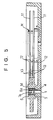
- a prior art hard disc drive as shown in Figs. 4 and 5 comprises a magnetic disc 11 which is driven for rotation by a motor M, and a swing arm (or head arm) 13 carrying at the end thereof a magnetic head 12 for writing data in the disc 13 at a predetermined position thereof and reading out data from the disc 13 at a given position thereof.
- the swing arm 13 has a stem rotatably supported by a compound bearing assembly which uses two ball bearing units.
- a prior art bearing assembly for supporting the swing arm comprises two ball bearing units A and B and a sleeve-like spacer C. These components of the bearing assembly are produced separately and supplied to the user, e.g. the hard disc drive manufacturer or the swing arm manufacturer, to be assembled on a shaft D.
- the assembly is not easily assembled by the user.
- An object of the invention is to provide a compound bearing assembly, which addresses the problems discussed above. It is an advantage of the present invention that the assembly can be used directly by a hard disc drive manufacturer for a swing arm of a hard disc drive.
- a plurality of balls are provided between an outer raceway groove formed in the inner periphery of an outer race ring and an inner raceway groove directly formed in the outer periphery of a largediameter portion of a stepped shaft, which has the largediameter portion and a small-diameter portion, and a plurality of other balls provided between an inner raceway groove formed in the outer periphery of an inner race ring fitted on the small-diameter portion of the stepped shaft and an outer raceway groove directly formed in the inner periphery of an end portion of a sleeve-like outer race ring.
- a plurality of balls are provided between an outer raceway groove directly formed in the inner periphery of an end portion of a sleeve-like outer race ring and an inner raceway groove directly formed in the outer periphery of a large-diameter portion of a stepped shaft, which has the large-diameter portion and a small-diameter portion, and a ball bearing unit having an inner and an outer race ring and a plurality of other balls provided therebetween has its inner race ring fitted on the small-diameter portion of the stepped shaft.
- a plurality of balls are provided between an inner raceway groove directly formed in the outer periphery of a large-diameter portion of a stepped shaft, which has the large-diameter portion and a small-diameter portion, and an outer raceway groove formed in the inner periphery of an outer race ring provided around the large-diameter portion, and a ball bearing unit having an inner and an outer race ring and a plurality of other balls provided therebetween has its inner race ring fitted on the small-diameter portion of the stepped shaft with a sleeve-like spacer clampedly interposed between the outer race ring of the ball bearing unit and the outer race ring provided around the large-diameter portion.
- the inner race ring fitted on the small-diameter portion of the stepped shaft has an equal outer diameter to the outer diameter of the large-diameter portion of the stepped shaft, so that all the balls are the same in diameter.
- the inner race ring of the ball bearing unit has an equal outer diameter to the outer diameter of the largediameter portion of the stepped shaft, and the outer race ring of the ball bearing unit has equal outer and inner diameters to the outer and inner diameters, respectively, of the sleeve-like outer race ring, so that all the balls are the same in diameter.
- a stepped shaft 1 has a first portion 1a having a larger diameter than a second portion 16, the large-diameter portion 1a having an inner raceway groove 2a formed directly in the outer periphery thereof.
- An outer race ring 3 is assembled on the larger diameter portion la of the stepped shaft 1 with a plurality of balls 4 provided between an outer raceway groove 2b formed in its inner periphery and the outer raceway groove 2a formed in the larger diameter portion 1a.
- a sleeve-like outer race ring 5 surrounds the stepped shaft 1 and has an outer raceway groove 6b formed directly in the inner periphery of its outer end portion (i.e., an upper end portion in Fig. 1).
- the sleeve-like outer race ring 5 is assembled on the stepped shaft 1 with a plurality of balls 8a provided between the outer raceway groove 6b and an inner raceway groove 6a formed in the outer periphery of an inner race ring 7a fitted on the smaller diameter portion 1b of the stepped shaft 1.
- the inner race ring 7a fitted on the small-diameter portion 1b of the stepped shaft 1 has an outer diameter equal to the outer diameter of the large-diameter portion 1a of the stepped shaft 1, so that the balls 5 and 8b are the same in diameter.
- the inner race ring 7a for instance, is initially slidably fitted on the smaller diameter portion 1b of the stepped shaft 1. Then, an adequate pre-load is applied to the outer end surface (i.e., upper end surface in Fig. 1) of the inner race ring 7a, and in this state the inner race ring 7a is secured by means of an adhesive to the smaller diameter portion 1b of the stepped shaft 1. In this way, the outer race ring 3, the sleeve-like outer race ring 5 and the inner race ring 7a are assembled on the stepped shaft 1.
- the sleeve-like outer race ring 5 and the outer race ring 3 are integrated into a compound member while the outer race ring 3, the sleeve-like outer race ring 5 and the inner race ring 7a are assembled on the stepped shaft 1.
- the stepped shaft 1 of the compound bearing assembly obtained in the above way is projected from the base of a hard disc drive by securing the stem of its larger diameter portion 1a to the base. Then, a boss 14 of a stem of a swing arm 13 is fitted on and secured by means of an adhesive to the compound bearing assembly.
- the swing arm 13 which is thus mounted on the compound bearing assembly is rotatable about the same.
- Fig. 2 shows a second embodiment of the invention.
- the larger diameter portion 1a of the stepped shaft 1 has the inner raceway groove 2a formed directly in the outer periphery thereof.
- a sleeve-like outer race ring 5 which surrounds the stepped shaft 1 has an outer raceway groove 2c formed directly in the inner periphery of an end portion (i.e., a lower end portion in Fig. 2) of it.
- the balls 4 are provided between the outer raceway groove 2c and the inner raceway groove 2a of the large-diameter portion 1a.
- a ball bearing unit 7 which has an inner and an outer race ring 7a and 7b and a plurality of balls 8b provided therebetween, has the inner race ring 7a fitted on and secured to the smaller diameter portion 1b of the stepped shaft 1.
- the inner race ring 7a of the ball bearing unit 7 has an outer diameter equal to the outer diameter of the larger diameter portion 1a of the stepped shaft 1, and the outer race ring 7b has outer and inner diameters equal to the outer and inner diameters, respectively, of the sleeve-like outer race ring 5, so that the balls 4 and 8b are the same in diameter.
- the inner race ring 7a of the ball bearing unit 7 is initially slidably fitted on the smaller diameter portion 1b of the stepped shaft 1. Then, an adequate pre-load is applied to the outer end surface (i.e., upper end surface in Fig. 2) of the inner race ring 7a, and in this state the inner race ring 7a is secured by means of an adhesive to the smaller diameter portion 1b of the stepped shaft 1.
- the sleeve-like outer race ring 5 and the outer race ring 7b of the ball bearing unit 7 are made integral to be a compound member, and the sleeve-like outer race ring 5, and the inner and outer race rings 7a and 7b of the ball bearing unit 7 are assembled on the stepped shaft 1.
- the stepped shaft of the compound bearing assembly is projected from a base of a hard disc drive by securing the stem of its larger diameter portion to the base, and then a boss 14 of a stem of a swing arm 13 is fitted on and secured by means of an adhesive to the compound bearing assembly.
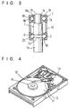
- Fig. 3 shows a third embodiment of the invention.
- an outer race ring 3 and a ball bearing unit 7 are provided on the larger and smaller diameter portions 1a and 1b of the stepped shaft 1, respectively, and a sleeve-like spacer 15 surrounding the stepped shaft 1 is fixedly interposed between the outer race ring 3 and the outer race ring 7b of the ball bearing unit 7.
- the inner race ring 7a of the ball bearing unit 7 has an outer diameter equal to the outer diameter of the larger diameter portion 1a of the stepped shaft 1, and the outer ring 7b of the ball bearing unit 7 has outer and inner diameters equal to the outer and inner diameters, respectively, of the outer race ring 3 around the larger diameter portion 1a, so that all the balls are the same in diameter.
- the inner race ring 7a of the ball bearing unit 7 is initially slidably fitted on the smaller diameter portion 1b of the stepped shaft 1, then an adequate pre-load is applied to the outer end surface (i.e., upper end surface in Fig. 3) of the inner race ring 7a, and in this state the inner race ring 7a is secured by means of an adhesive to the smaller diameter portion 1b of the stepped shaft 1.
- the spacer 15 and the opposite end outer race rings 3 and 7b are made integral to be a compound sleeve-like outer race ring, and the outer race rings 3 and 7b, the spacer 15 and the inner race ring 7a are assembled on the stepped shaft 1.
- the stepped shaft 1 of the compound bearing assembly is projected from a base of a hard disc drive by securing the stem of its larger diameter portion to the base, and a boss 14 of a stem of a. swing arm 13 is fitted on and secured by means of an adhesive to the compound bearing assembly.
- raceway grooves 9a and 9b are formed in the inner and outer race rings 7a and 7b of the ball bearing unit 7, respectively, and the balls 8a are held in place by ball retainers 10.
Landscapes
- Engineering & Computer Science (AREA)
- General Engineering & Computer Science (AREA)
- Mechanical Engineering (AREA)
- Rolling Contact Bearings (AREA)
- Moving Of Heads (AREA)
- Mounting Of Bearings Or Others (AREA)
- Catalysts (AREA)
Abstract
Description
- This invention relates to a compound bearing assembly for supporting a swing arm of a hard disc drive.
- A prior art hard disc drive as shown in Figs. 4 and 5, comprises a
magnetic disc 11 which is driven for rotation by a motor M, and a swing arm (or head arm) 13 carrying at the end thereof amagnetic head 12 for writing data in thedisc 13 at a predetermined position thereof and reading out data from thedisc 13 at a given position thereof. - The
swing arm 13 has a stem rotatably supported by a compound bearing assembly which uses two ball bearing units. As shown in Fig. 6, a prior art bearing assembly for supporting the swing arm comprises two ball bearing units A and B and a sleeve-like spacer C. These components of the bearing assembly are produced separately and supplied to the user, e.g. the hard disc drive manufacturer or the swing arm manufacturer, to be assembled on a shaft D. - In other words, with the conventional swing arm support bearing assembly, the user has to assemble the two ball bearing units on the shaft separated by the spacer. This poses the following problems.
- (a) The shaft has to be manufactured so as to match the inner diameter of the inner race rings of the ball bearing units. In addition, its rigidity is subject to restrictions.
- (b) the spacer must be highly accurately produced, with parallel and flat opposite end finished surfaces.
- (c) it is necessary to provide uniform contact between the opposite end surfaces of the spacer and the corresponding end surfaces of the outer race rings of the ball bearing units, thus requiring highly accurate finishing.
- For the above reasons, the assembly is not easily assembled by the user.
- An object of the invention is to provide a compound bearing assembly, which addresses the problems discussed above. It is an advantage of the present invention that the assembly can be used directly by a hard disc drive manufacturer for a swing arm of a hard disc drive.
- In a compound bearing assembly for a swing arm according to a first aspect of the invention, a plurality of balls are provided between an outer raceway groove formed in the inner periphery of an outer race ring and an inner raceway groove directly formed in the outer periphery of a largediameter portion of a stepped shaft, which has the largediameter portion and a small-diameter portion, and a plurality of other balls provided between an inner raceway groove formed in the outer periphery of an inner race ring fitted on the small-diameter portion of the stepped shaft and an outer raceway groove directly formed in the inner periphery of an end portion of a sleeve-like outer race ring.
- In a compound bearing assembly for a swing arm according to a second aspect of the invention, a plurality of balls are provided between an outer raceway groove directly formed in the inner periphery of an end portion of a sleeve-like outer race ring and an inner raceway groove directly formed in the outer periphery of a large-diameter portion of a stepped shaft, which has the large-diameter portion and a small-diameter portion, and a ball bearing unit having an inner and an outer race ring and a plurality of other balls provided therebetween has its inner race ring fitted on the small-diameter portion of the stepped shaft.
- In a compound bearing assembly for a swing arm according to a third aspect of the invention, a plurality of balls are provided between an inner raceway groove directly formed in the outer periphery of a large-diameter portion of a stepped shaft, which has the large-diameter portion and a small-diameter portion, and an outer raceway groove formed in the inner periphery of an outer race ring provided around the large-diameter portion, and a ball bearing unit having an inner and an outer race ring and a plurality of other balls provided therebetween has its inner race ring fitted on the small-diameter portion of the stepped shaft with a sleeve-like spacer clampedly interposed between the outer race ring of the ball bearing unit and the outer race ring provided around the large-diameter portion.
- According to the first aspect of the invention, the inner race ring fitted on the small-diameter portion of the stepped shaft has an equal outer diameter to the outer diameter of the large-diameter portion of the stepped shaft, so that all the balls are the same in diameter.
- According to the second and third aspects of the invention, the inner race ring of the ball bearing unit has an equal outer diameter to the outer diameter of the largediameter portion of the stepped shaft, and the outer race ring of the ball bearing unit has equal outer and inner diameters to the outer and inner diameters, respectively, of the sleeve-like outer race ring, so that all the balls are the same in diameter.
- Embodiments of the present invnetion will now be described, by way of example, with reference to the accompanying drawings, in which:-
- Fig. 1 is a sectional view showing a first embodiment of the compound bearing assembly in accordance with the invention;
- Fig. 2 is a sectional view showing a second embodiment of the compound bearing assembly in accordance with the invention;
- Fig. 3 is a sectional view showing a third embodiment of the compound bearing assembly in accordance with the invention;
- Fig. 4 is a perspective view showing a hard disc drive;
- Fig. 5 is a sectional view showing a swing arm supported by a compound bearing assembly in accordance with a first aspect of the invention; and
- Figs. 6(a) and 6(b) are sectional views showing a prior art swing arm bearing assembly, Fig. 6(a) showing ball bearing units and a sleeve-like spacer before being assembled, Fig. 6(b) showing the ball bearing units and sleeve-like spacer having been assembled on a shaft.
- Referring to Fig. 1 a first embodiment of the invention is illustrated, in which a
stepped shaft 1 has afirst portion 1a having a larger diameter than a second portion 16, the large-diameter portion 1a having aninner raceway groove 2a formed directly in the outer periphery thereof. - An
outer race ring 3 is assembled on the larger diameter portion la of thestepped shaft 1 with a plurality ofballs 4 provided between anouter raceway groove 2b formed in its inner periphery and theouter raceway groove 2a formed in thelarger diameter portion 1a. - A sleeve-like
outer race ring 5, surrounds thestepped shaft 1 and has an outer raceway groove 6b formed directly in the inner periphery of its outer end portion (i.e., an upper end portion in Fig. 1). The sleeve-likeouter race ring 5 is assembled on thestepped shaft 1 with a plurality ofballs 8a provided between the outer raceway groove 6b and an inner raceway groove 6a formed in the outer periphery of aninner race ring 7a fitted on thesmaller diameter portion 1b of thestepped shaft 1. - The
inner race ring 7a fitted on the small-diameter portion 1b of thestepped shaft 1 has an outer diameter equal to the outer diameter of the large-diameter portion 1a of thestepped shaft 1, so that theballs - In consutructing the assembly, the
inner race ring 7a, for instance, is initially slidably fitted on thesmaller diameter portion 1b of thestepped shaft 1. Then, an adequate pre-load is applied to the outer end surface (i.e., upper end surface in Fig. 1) of theinner race ring 7a, and in this state theinner race ring 7a is secured by means of an adhesive to thesmaller diameter portion 1b of thestepped shaft 1. In this way, theouter race ring 3, the sleeve-likeouter race ring 5 and theinner race ring 7a are assembled on thestepped shaft 1. - In this structure, the sleeve-like
outer race ring 5 and theouter race ring 3 are integrated into a compound member while theouter race ring 3, the sleeve-likeouter race ring 5 and theinner race ring 7a are assembled on thestepped shaft 1. - As shown in Fig. 5, the
stepped shaft 1 of the compound bearing assembly obtained in the above way, is projected from the base of a hard disc drive by securing the stem of itslarger diameter portion 1a to the base. Then, aboss 14 of a stem of aswing arm 13 is fitted on and secured by means of an adhesive to the compound bearing assembly. - The
swing arm 13 which is thus mounted on the compound bearing assembly is rotatable about the same. - Fig. 2 shows a second embodiment of the invention. Again in this embodiment, the
larger diameter portion 1a of thestepped shaft 1 has theinner raceway groove 2a formed directly in the outer periphery thereof. - In this embodiment, a sleeve-like
outer race ring 5 which surrounds thestepped shaft 1 has anouter raceway groove 2c formed directly in the inner periphery of an end portion (i.e., a lower end portion in Fig. 2) of it. Theballs 4 are provided between theouter raceway groove 2c and theinner raceway groove 2a of the large-diameter portion 1a. - A ball bearing
unit 7 which has an inner and anouter race ring balls 8b provided therebetween, has theinner race ring 7a fitted on and secured to thesmaller diameter portion 1b of thestepped shaft 1. - The
inner race ring 7a of the ball bearingunit 7 has an outer diameter equal to the outer diameter of thelarger diameter portion 1a of thestepped shaft 1, and theouter race ring 7b has outer and inner diameters equal to the outer and inner diameters, respectively, of the sleeve-likeouter race ring 5, so that theballs - In constructing the assembly, the
inner race ring 7a of the ball bearingunit 7, for instance, is initially slidably fitted on thesmaller diameter portion 1b of thestepped shaft 1. Then, an adequate pre-load is applied to the outer end surface (i.e., upper end surface in Fig. 2) of theinner race ring 7a, and in this state theinner race ring 7a is secured by means of an adhesive to thesmaller diameter portion 1b of thestepped shaft 1. - In this way, the sleeve-like
outer race ring 5 and theouter race ring 7b of the ball bearingunit 7 are made integral to be a compound member, and the sleeve-likeouter race ring 5, and the inner andouter race rings unit 7 are assembled on thestepped shaft 1. - As described above, the stepped shaft of the compound bearing assembly thus obtained, is projected from a base of a hard disc drive by securing the stem of its larger diameter portion to the base, and then a
boss 14 of a stem of aswing arm 13 is fitted on and secured by means of an adhesive to the compound bearing assembly. - Fig. 3 shows a third embodiment of the invention.
- In this embodiment, an
outer race ring 3 and a ball bearingunit 7 are provided on the larger andsmaller diameter portions stepped shaft 1, respectively, and a sleeve-like spacer 15 surrounding thestepped shaft 1 is fixedly interposed between theouter race ring 3 and theouter race ring 7b of the ball bearingunit 7. - The
inner race ring 7a of the ball bearingunit 7 has an outer diameter equal to the outer diameter of thelarger diameter portion 1a of thestepped shaft 1, and theouter ring 7b of the ball bearingunit 7 has outer and inner diameters equal to the outer and inner diameters, respectively, of theouter race ring 3 around thelarger diameter portion 1a, so that all the balls are the same in diameter. - In constructing the assembly like the preceding second embodiment, the
inner race ring 7a of the ball bearingunit 7 is initially slidably fitted on thesmaller diameter portion 1b of thestepped shaft 1, then an adequate pre-load is applied to the outer end surface (i.e., upper end surface in Fig. 3) of theinner race ring 7a, and in this state theinner race ring 7a is secured by means of an adhesive to thesmaller diameter portion 1b of thestepped shaft 1. - In this way, the
spacer 15 and the opposite endouter race rings outer race rings spacer 15 and theinner race ring 7a are assembled on thestepped shaft 1. - Like the above first and second embodiments, the
stepped shaft 1 of the compound bearing assembly thus obtained, is projected from a base of a hard disc drive by securing the stem of its larger diameter portion to the base, and aboss 14 of a stem of a.swing arm 13 is fitted on and secured by means of an adhesive to the compound bearing assembly. - The
raceway grooves outer race rings unit 7, respectively, and theballs 8a are held in place byball retainers 10. - While in the above first to third embodiments the balls that were used were all the same in diameter, it is possible to use balls of different diameters on the sides of the larger and
smaller diameter portions stepped shaft 1, respectively. - With the compound bearing assembly for a swing arm constructed as described in the foregoing, the following advantageous functions and effects are obtainable.
- (1) Since the components of the compound bearing assembly, i.e., the sleeve-like outer race ring or spacer, the inner race ring, the outer race ring, the balls and the snaft, are all assembled by the bearing assembly manufacturer, the user need not assembly any of these components, and the compound bearing assembly can be readily and reliably mounted on a swing arm of a hard disc drive by fitting the swing
arm stem boss 14 on and securing the same by means of an adhesive. - (2) Since the larger diameter portion of the stepped shaft in the bearing assembly has the inner raceway groove directly formed in its outer periphery, the conventional inner race ring is unnecessary, and correspondingly the shaft is partly increased in diameter producing a stepped shaft, which thus has increased rigidity.
- (3) Only a single conventional ball bearing unit, and hence only a single inner race ring, is needed, and it is possible to provide a bearing assembly having a reduced number of components.
- (4) In the first and second embodiments of the invention, the sleeve-like outer race ring also serves as a spacer, and the conventional spacer is unnecessary, thus permitting reduction of the number of components.
- (5) The sleeve-like outer race ring or the spacer is fabricated highly accurately by the bearing assembly manufacturer, thus improving the accuracy of the overall assembly.
Claims (4)
- A compound bearing assembly for a swing arm (13) of a hard disc drive comprising:a stepped shaft (1) having a first portion (1a) with a larger diameter than a second portion (1b), said larger diameter portion (1a) having an inner raceway groove (2a) formed directly in the inner periphery thereof;a sleeve-like outer race ring (5) surrounding said stepped shaft (1) and having a distinct outer race ring (3) provided adjacent one end and also having an outer raceway groove formed directly in the inner periphery of a portion adjacent the other end thereof;a plurality of balls (4) received in said inner raceway groove (2a) directly formed in said larger diameter portion (1a) and retained in an outer raceway groove (2b) formed in said outer race ring (3) or said outer raceway groove (2c) directly formed in said sleeve-like outer race ring (5); anda plurality of other balls (8a) received in an inner race way groove formed in an inner race ring (7a) fitted on said smaller diameter portion (1b) of said stepped shaft (1) and retained in said outer raceway groove (2b) formed directly in the inner periphery of said sleeve-like outer race ring (5) or an outer raceway groove (9b) formed in the inner periphery of said outer race ring (7b).
- A compound bearing assembly as claimed in claim 1, wherein said balls (4) received in said inner raceway groove (2a) are retained in said outer raceway groove (2b) formed in said outer race ring (3), and said balls (8a) received in said inner raceway groove (6a) formed in said inner race ring (7a) fitted on said smaller diameter poriton (1b) are retained in said outer raceway groove (6b) directly formed in the inner periphery of said sleeve-like outer race ring (5).
- A compound bearing assembly as claimed in claim 1, wherein said balls (4) received in said inner raceway groove (2a) are retained in said outer raceway groove (2c) directly formed in the inner periphery of said sleeve-like outer race ring (5), and said balls (8b) received in said inner raceway groove (9a) formed in said inner race ring (7a) fitted on said small diameter portion (1b) are retained in said outer raceway groove (9b) formed in the inner periphery of said outer race ring (7b).
- A compound bearing assembly for a swing arm of a hard disc drive comprising:a stepped shaft (1) having a first portion (1a) with a larger diameter than a second portion (1b), said larger diameter portion (1a) having an inner raceway groove (2a) formed directly in the outer periphery thereof;an outer ring (3) being provided around said larger diameter portion (1a);a plurality of balls (4) provided between said inner raceway groove (2a) and an outer raceway groove (2b) formed in the inner periphery of said outer race ring (3);a ball bearing unit (7) having an inner and an outer race ring (7a) and (7c) and a plurality of other balls (8b), said inner race ring (7a) of said ball bearing unit (7) being fitted on said smaller diameter portion (1b) of said stepped shaft (1); anda sleeve-like spacer (16) fixedly interposed between said outer race ring (7b) of said ball bearing unit (7) and said outer race ring (3) around said larger diameter portion (1a).
Priority Applications (1)
| Application Number | Priority Date | Filing Date | Title |
|---|---|---|---|
| EP01127085A EP1207530A1 (en) | 1995-10-25 | 1996-10-23 | Compound bearing assembly for the swing arm of a hard disc drive |
Applications Claiming Priority (6)
| Application Number | Priority Date | Filing Date | Title |
|---|---|---|---|
| JP30060995A JPH09119435A (en) | 1995-10-25 | 1995-10-25 | Compound bearing for swing arm |
| JP30060895A JPH09119434A (en) | 1995-10-25 | 1995-10-25 | Compound bearing for swing arm |
| JP300608/95 | 1995-10-25 | ||
| JP30060895 | 1995-10-25 | ||
| JP300609/95 | 1995-10-25 | ||
| JP30060995 | 1995-10-25 |
Related Child Applications (1)
| Application Number | Title | Priority Date | Filing Date |
|---|---|---|---|
| EP01127085A Division EP1207530A1 (en) | 1995-10-25 | 1996-10-23 | Compound bearing assembly for the swing arm of a hard disc drive |
Publications (3)
| Publication Number | Publication Date |
|---|---|
| EP0771002A2 true EP0771002A2 (en) | 1997-05-02 |
| EP0771002A3 EP0771002A3 (en) | 1998-01-07 |
| EP0771002B1 EP0771002B1 (en) | 2002-05-29 |
Family
ID=26562391
Family Applications (2)
| Application Number | Title | Priority Date | Filing Date |
|---|---|---|---|
| EP96307656A Expired - Lifetime EP0771002B1 (en) | 1995-10-25 | 1996-10-23 | Compound bearing assembly for the swing arm of a hard disc drive |
| EP01127085A Withdrawn EP1207530A1 (en) | 1995-10-25 | 1996-10-23 | Compound bearing assembly for the swing arm of a hard disc drive |
Family Applications After (1)
| Application Number | Title | Priority Date | Filing Date |
|---|---|---|---|
| EP01127085A Withdrawn EP1207530A1 (en) | 1995-10-25 | 1996-10-23 | Compound bearing assembly for the swing arm of a hard disc drive |
Country Status (3)
| Country | Link |
|---|---|
| US (1) | US6227714B1 (en) |
| EP (2) | EP0771002B1 (en) |
| DE (1) | DE69621399T2 (en) |
Cited By (6)
| Publication number | Priority date | Publication date | Assignee | Title |
|---|---|---|---|---|
| US6181513B1 (en) * | 1998-05-14 | 2001-01-30 | Minebea Kabushiki-Kaisha | Spindle motor and a hard disk drive apparatus including such a motor |
| EP1150017A3 (en) * | 2000-04-28 | 2003-01-15 | Minebea Kabushiki Kaisha | Blower |
| EP1174623A3 (en) * | 2000-07-21 | 2003-02-05 | Minebea Kabushiki Kaisha | Blower |
| EP1134423A3 (en) * | 2000-03-14 | 2003-02-05 | Minebea Kabushiki Kaisha | A blower |
| US6687092B2 (en) * | 2001-05-10 | 2004-02-03 | Hitachi Global Storage Technologies Netherland B.V. | Pivot bearing assembly for compensating for disk drive actuator tilt |
| EP1288917A3 (en) * | 2001-08-31 | 2005-02-02 | Minebea Kabushiki Kaisha | Pivot bearing for a swing arm of a hard disk drive device |
Families Citing this family (3)
| Publication number | Priority date | Publication date | Assignee | Title |
|---|---|---|---|---|
| JP2001140869A (en) * | 1999-11-19 | 2001-05-22 | Minebea Co Ltd | Double-row bearing |
| FR2894986B1 (en) * | 2005-12-16 | 2008-05-02 | Centre Nat Rech Scient | PREPARATION OF A MATERIAL COMPRISING A MIXTURE OF NOBLE METAL NANOPARTICLES AND RARE EARTH OXIDE NANOPARTICLES |
| CN104648041A (en) * | 2013-11-25 | 2015-05-27 | 慈溪市创立轴承有限公司 | Handcart caster |
Family Cites Families (8)
| Publication number | Priority date | Publication date | Assignee | Title |
|---|---|---|---|---|
| DE3419814C1 (en) * | 1984-05-26 | 1985-11-28 | GMN Georg Müller Nürnberg GmbH, 8500 Nürnberg | Motor spindle for magnetic disk storage |
| USRE34684E (en) * | 1987-05-08 | 1994-08-02 | Nagano Nidec Corporation | Drive motor for magnetic disks, optical disks, and magneto-optical disks |
| US5109310A (en) * | 1989-03-07 | 1992-04-28 | Alps Electric Co., Ltd. | Disk drive device with unified actuator assembly |
| EP0571580B1 (en) * | 1991-12-12 | 1995-05-10 | Barmag Ag | Frictional false-twisting unit |
| JP3419015B2 (en) * | 1992-02-24 | 2003-06-23 | 日本精工株式会社 | Manufacturing method of rolling bearing device to which preload is applied |
| US5556209A (en) * | 1992-10-06 | 1996-09-17 | Minebea Kabushiki-Kaisha | Double-row ball bearing |
| JP3312942B2 (en) * | 1993-02-23 | 2002-08-12 | ミネベア株式会社 | Magnetic disk drive |
| US5547291A (en) * | 1993-09-29 | 1996-08-20 | Nsk, Ltd. | Preloaded rolling bearing units |
-
1996
- 1996-10-23 DE DE69621399T patent/DE69621399T2/en not_active Expired - Fee Related
- 1996-10-23 EP EP96307656A patent/EP0771002B1/en not_active Expired - Lifetime
- 1996-10-23 EP EP01127085A patent/EP1207530A1/en not_active Withdrawn
- 1996-10-24 US US08/736,451 patent/US6227714B1/en not_active Expired - Fee Related
Non-Patent Citations (1)
| Title |
|---|
| None |
Cited By (7)
| Publication number | Priority date | Publication date | Assignee | Title |
|---|---|---|---|---|
| US6181513B1 (en) * | 1998-05-14 | 2001-01-30 | Minebea Kabushiki-Kaisha | Spindle motor and a hard disk drive apparatus including such a motor |
| EP1134423A3 (en) * | 2000-03-14 | 2003-02-05 | Minebea Kabushiki Kaisha | A blower |
| EP1150017A3 (en) * | 2000-04-28 | 2003-01-15 | Minebea Kabushiki Kaisha | Blower |
| US6916160B2 (en) | 2000-04-28 | 2005-07-12 | Minebea Kabushiki-Kaisha | Axial electric fan blower with electric components housing sealed from moisture, dirt and dust or other harmful gas |
| EP1174623A3 (en) * | 2000-07-21 | 2003-02-05 | Minebea Kabushiki Kaisha | Blower |
| US6687092B2 (en) * | 2001-05-10 | 2004-02-03 | Hitachi Global Storage Technologies Netherland B.V. | Pivot bearing assembly for compensating for disk drive actuator tilt |
| EP1288917A3 (en) * | 2001-08-31 | 2005-02-02 | Minebea Kabushiki Kaisha | Pivot bearing for a swing arm of a hard disk drive device |
Also Published As
| Publication number | Publication date |
|---|---|
| DE69621399D1 (en) | 2002-07-04 |
| EP0771002B1 (en) | 2002-05-29 |
| EP0771002A3 (en) | 1998-01-07 |
| EP1207530A9 (en) | 2002-09-11 |
| EP1207530A1 (en) | 2002-05-22 |
| US6227714B1 (en) | 2001-05-08 |
| DE69621399T2 (en) | 2002-12-12 |
Similar Documents
| Publication | Publication Date | Title |
|---|---|---|
| EP0592214A2 (en) | Compound ball-bearing | |
| EP0771002B1 (en) | Compound bearing assembly for the swing arm of a hard disc drive | |
| EP0752539B1 (en) | Bearing assembly and method of manufacturing the same | |
| EP0771003B1 (en) | Compound bearing assembly for the swing arm of a hard disc drive | |
| JPWO1996029521A1 (en) | Bearing assembly, spindle motor and actuator using the bearing assembly, and magnetic disk drive | |
| WO1996029521A1 (en) | Bearing assembly, spindle motor and actuator using the same bearing assembly, and magnetic disk device | |
| US7056030B2 (en) | Pivot bearing for a swing arm of a hard disk drive device | |
| JPH10227310A (en) | Double row bearing device | |
| US5820273A (en) | Hard disc drive with a compound bearing assembly | |
| EP0770999B1 (en) | Hard disc drive with a compound bearing assembly | |
| EP0859361B1 (en) | Hard disk drive device | |
| EP0859445A2 (en) | Motor | |
| JP2566504Y2 (en) | Double row angular contact ball bearing and hard disk drive using the same | |
| JP3647529B2 (en) | Bearing, motor using the same, and recording / reproducing apparatus using the motor | |
| JPH09149585A (en) | Bearing of rotary shaft, and its assembly method | |
| JP2593689Y2 (en) | Disc clamp device | |
| JPS6069320A (en) | Shaft unit with bearing | |
| JP2897114B2 (en) | Composite bearing device and method of manufacturing the same | |
| JPH09119434A (en) | Compound bearing for swing arm | |
| US20020094142A1 (en) | Pivot bearing | |
| JPH04114771U (en) | step motor | |
| JPH0921417A (en) | Bearing device and manufacture thereof | |
| JPH0527333U (en) | Bearing device | |
| JPH0956108A (en) | Motor with composite bearing unit | |
| JPH09112547A (en) | Hard disk driving device furnished with complex bearing device |
Legal Events
| Date | Code | Title | Description |
|---|---|---|---|
| PUAI | Public reference made under article 153(3) epc to a published international application that has entered the european phase |
Free format text: ORIGINAL CODE: 0009012 |
|
| AK | Designated contracting states |
Kind code of ref document: A2 Designated state(s): DE FR GB |
|
| PUAL | Search report despatched |
Free format text: ORIGINAL CODE: 0009013 |
|
| AK | Designated contracting states |
Kind code of ref document: A3 Designated state(s): DE FR GB |
|
| 17P | Request for examination filed |
Effective date: 19980522 |
|
| 17Q | First examination report despatched |
Effective date: 20000614 |
|
| GRAG | Despatch of communication of intention to grant |
Free format text: ORIGINAL CODE: EPIDOS AGRA |
|
| GRAG | Despatch of communication of intention to grant |
Free format text: ORIGINAL CODE: EPIDOS AGRA |
|
| GRAH | Despatch of communication of intention to grant a patent |
Free format text: ORIGINAL CODE: EPIDOS IGRA |
|
| GRAH | Despatch of communication of intention to grant a patent |
Free format text: ORIGINAL CODE: EPIDOS IGRA |
|
| GRAA | (expected) grant |
Free format text: ORIGINAL CODE: 0009210 |
|
| AK | Designated contracting states |
Kind code of ref document: B1 Designated state(s): DE FR GB |
|
| REG | Reference to a national code |
Ref country code: GB Ref legal event code: FG4D |
|
| REF | Corresponds to: |
Ref document number: 69621399 Country of ref document: DE Date of ref document: 20020704 |
|
| ET | Fr: translation filed | ||
| PLBE | No opposition filed within time limit |
Free format text: ORIGINAL CODE: 0009261 |
|
| STAA | Information on the status of an ep patent application or granted ep patent |
Free format text: STATUS: NO OPPOSITION FILED WITHIN TIME LIMIT |
|
| 26N | No opposition filed |
Effective date: 20030303 |
|
| PGFP | Annual fee paid to national office [announced via postgrant information from national office to epo] |
Ref country code: DE Payment date: 20071018 Year of fee payment: 12 |
|
| PGFP | Annual fee paid to national office [announced via postgrant information from national office to epo] |
Ref country code: GB Payment date: 20071017 Year of fee payment: 12 Ref country code: FR Payment date: 20071009 Year of fee payment: 12 |
|
| GBPC | Gb: european patent ceased through non-payment of renewal fee |
Effective date: 20081023 |
|
| REG | Reference to a national code |
Ref country code: FR Ref legal event code: ST Effective date: 20090630 |
|
| PG25 | Lapsed in a contracting state [announced via postgrant information from national office to epo] |
Ref country code: DE Free format text: LAPSE BECAUSE OF NON-PAYMENT OF DUE FEES Effective date: 20090501 |
|
| PG25 | Lapsed in a contracting state [announced via postgrant information from national office to epo] |
Ref country code: FR Free format text: LAPSE BECAUSE OF NON-PAYMENT OF DUE FEES Effective date: 20081031 |
|
| PG25 | Lapsed in a contracting state [announced via postgrant information from national office to epo] |
Ref country code: GB Free format text: LAPSE BECAUSE OF NON-PAYMENT OF DUE FEES Effective date: 20081023 |