EP0771116A2 - Bildverarbeitungsvorrichtung - Google Patents
Bildverarbeitungsvorrichtung Download PDFInfo
- Publication number
- EP0771116A2 EP0771116A2 EP96307722A EP96307722A EP0771116A2 EP 0771116 A2 EP0771116 A2 EP 0771116A2 EP 96307722 A EP96307722 A EP 96307722A EP 96307722 A EP96307722 A EP 96307722A EP 0771116 A2 EP0771116 A2 EP 0771116A2
- Authority
- EP
- European Patent Office
- Prior art keywords
- signal
- regions
- picture
- picture signal
- filter
- Prior art date
- Legal status (The legal status is an assumption and is not a legal conclusion. Google has not performed a legal analysis and makes no representation as to the accuracy of the status listed.)
- Withdrawn
Links
Images






Classifications
-
- H—ELECTRICITY
- H04—ELECTRIC COMMUNICATION TECHNIQUE
- H04N—PICTORIAL COMMUNICATION, e.g. TELEVISION
- H04N19/00—Methods or arrangements for coding, decoding, compressing or decompressing digital video signals
- H04N19/80—Details of filtering operations specially adapted for video compression, e.g. for pixel interpolation
-
- H—ELECTRICITY
- H04—ELECTRIC COMMUNICATION TECHNIQUE
- H04N—PICTORIAL COMMUNICATION, e.g. TELEVISION
- H04N19/00—Methods or arrangements for coding, decoding, compressing or decompressing digital video signals
- H04N19/20—Methods or arrangements for coding, decoding, compressing or decompressing digital video signals using video object coding
Definitions
- This invention relates to an image processing apparatus, and more particularly to an image processing apparatus suitable for reducing block distortions occurring in the decoded image in an image encoding/ decoding system that compression-codes images into a small amount of data and reproduces the images by decoding the code string obtained through compression coding.
- the input picture signal is divided into a plurality of blocks and then each block undergoes motion compensation adaptive prediction. Specifically, the motion vector between the input picture signal and the reference picture signal of the preceding frame is sensed and a prediction signal is created by performing motion compensation on the reference picture signal using the motion vector.
- the prediction signal is subtracted from the input picture signal to produce a prediction error signal.
- the prediction error signal undergoes discrete cosine transform (DCT) in blocks of a specific size.
- DCT discrete cosine transform
- the quantized DCT coefficients are subjected to variable-length coding and then are multiplexed with coded motion vector information and thereafter the resulting signal is outputted as a code string.
- the code string is dequantized and then is subjected to inverse discrete cosine transform.
- the prediction error signal restored by inverse discrete cosine transform is added to the adaptive prediction signal to produce a local decoded signal.
- the local decoded signal is stored in a frame memory as a reference picture signal.
- the code string that has been transferred from the motion picture encoding apparatus and has been stored is inputted to the motion picture decoding apparatus, which then separates the code string into the quantized DCT coefficients and the motion vector information.
- the quantized DCT coefficients are subjected to variable-length decoding, dequantization, and inverse discrete cosine transform and is thereby reconstructed into a prediction error signal.
- the motion vector information undergoes variable-length decoding and thereafter a motion compensation prediction process.
- motion compensation motion compensation is performed on the reference picture signal of the preceding frame stored in the frame memory to produce a prediction signal.
- the prediction signal is added to the prediction error signal. This addition produces a picture signal.
- the reproduced picture signal is outputted outside the decoding apparatus and is also stored in the frame memory as a reference picture signal.
- the aforementioned conventional motion-picture encoding/decoding apparatus has the following problems.
- AC component prediction scheme using average value has been proposed as a method of predicting the AC components lost in quantization (reference 2: Watanabe and Ohzeki, "Evaluation of an Alternating-Current Component Prediction Scheme Using Average Value," the 1989 picture coding symposium (PCSJ89), 2-2, 1989). Additionally, several other AC prediction schemes have been proposed.
- the conventional AC component prediction schemes were based on the assumption that the AC component prediction process is carried out before discrete cosine transform in the coding process.
- the prediction schemes were not used for removal of block distortions occurred in the decoded pictures. Even if the conventional AC prediction schemes were applied directly to the decoded pictures, the predictable AC components would be limited to only the low-frequency AC components close to a direct current (DC) and the high-frequency AC components in the decoded pictures would be removed.
- DC direct current
- quantization causes quantization distortion called mosquito noise around the edge portion, degrading the picture quality.
- the distortion has particularly a great effect on a flat domain adjacent to the edge portion.
- a nonrecursive 5 ⁇ 5 adaptive smoothing filter has been proposed as a method of reducing the distortion (reference 4: Kato and Ohkubo, "Improvement of High-Efficiency Coding Picture Quality by Post Filtering", Proceedings 1989 Electric Information Communications Society Autumn National Meeting, Vol. 6, D-3, D-63). Since the method eliminates the high-frequency AC components by applying the filter to the entire screen, the edge portion is blurred a little.
- the conventional motion-picture encoding/decoding apparatus has the problem that block distortions occur at the boundary between blocks as a result of carrying out the processing block by block and lattice distortions appear conspicuously.
- the conventional method of reducing the distortions is complex in processing. Furthermore, because the method of simply predicting the lost AC components removes the AC components from the blocks originally having the high-frequency AC components, it has an adverse effect on the picture quality.
- An object of the present invention is to provide an image processing apparatus which not only compensates for the lost AC components without the adverse effects of AC components prediction by applying AC component prediction only to the domain where the AC components have been lost, but also requires no complex process like a conventional block distortion reducing method.
- Another object of the present invention is to provide an image processing apparatus capable of effectively reducing encoding distortions in the decoded picture signal, and noises and flicker before the coding of the picture signal.
- Still another object of the present invention is to provide an apparatus for and method of processing images which examine the local characteristics of the images whose picture quality has deteriorated as a result of coding and control the intensity of smoothing of the filter so that degradation of the picture quality may be inconspicuous, thereby improving the picture quality.
- an image processing apparatus that not only judges whether or not the region is a flat domain for each specific region of an input picture signal, but also predicts the AC components from the input picture signal, allocates the signals containing the predicted AC components to the regions judged to be flat domains and the input picture signal to the other regions.
- each domain of the input picture signal is a flat domain is such that, for example, the nature of the picture of the input picture signal is judged domain by domain and the domains where the AC components are equal to or less than a specific value are judged to be flat domains and the other domains are judged to be nonflat domains.
- the AC components of the domains are predicted from the picture signals of the surrounding domains and the resulting signals are outputted.
- an image processing apparatus that not only judges whether the domain is an edge, a flat domain, or a nonflat domain for the input picture signal, replaces the domains of the input picture signal judged to be edges and nonflat domains with the picture signals of the regions judged to be flat domains, and allocates the input picture signal to the other domains, but also predicts the AC components for each domain of the outputted picture signal and outputs the signals containing the predicted AC components for the domains judged to be flat domains and the input picture signal for the other domains.
- the domains judged to be nonflat domains may include flat domains in part. Therefore, the nonflat domains adjacent to the flat domains are judged to be edge portions.
- the flat domains are also subjected to AC component prediction.
- a video signal processing apparatus comprising time filter means that performs a filtering process on an input picture signal with respect to time according to a specific filter coefficient and outputs an output picture signal, and filter coefficient decision means that determines a filter coefficient in the time filter means according to at least the amount of the difference between the input picture signal and the signal obtained by delaying the output video signal or between the input picture signal and the signal obtained by delaying the input picture signal.
- the filter coefficient decision means determines a filter coefficient in the time filter means according to at least (a) the amount of the difference between the input picture signal and the signal obtained by delaying the output picture signal or between the input picture signal and the signal obtained by delaying the input picture signal and (b) the encoding mode of the video encoding apparatus.
- encoding distortions which are particularly conspicuous in the still portions, are effectively alleviated by determining the filter coefficient so that the signal subjected to relatively intense time filtering may be outputted as an output picture signal in the portions where the amount of the difference between the input picture signal and the signal obtained by delaying the output picture signal or between the input picture signal and the signal obtained by delaying the input picture signal is small, that is, the still portions.
- the large change in the picture is prevented from being left in the form of an afterimage by determining the filter coefficient so that the decoded picture signal may be outputted as it is or the decoded picture signal subjected to less intense time filtering may be outputted as an output picture signal.
- the filter coefficient is determined, taking the encoding mode into account, the unnaturalness of the decoded picture resulting from the difference in encoding method between the encoding mode (intra-frame encoding mode) of the portions for which refresh encoding has been done and the encoding mode (motion compensation prediction encoding mode) of the other portions, is overcome by, for example, setting a filter coefficient so that the portion for which refresh encoding has been done may be subjected to relatively intense time filtering.
- the filter coefficient may be determined, taking into account activity, or an evaluation value indicating the complexity of a picture.
- the blurring of the picture caused by time filtering is made less by applying less intense time filtering to the edges with high activity or to the portions containing fine patterns or by outputting the input picture signal as it is.
- encoding distortions are effectively suppressed by applying intense time filtering to the flat domains where the activity is low and encoding distortions tend to be conspicuous.
- the time filtering process and the determination of a filter coefficient may be carried out after the low-level pixel removing process.
- the low-level pixel removing process is such that the pixel signals of low-level pixels which exist at the edge of the picture and whose pixel values are equal to or smaller than a threshold value are removed from the input picture signal.
- the low-level pixel removing process that the pixel signals of low-level pixels which exist at the edge of the picture and whose pixel values are equal to or smaller than the threshold value are removed from the input picture signal is realized by sensing the low-level pixels whose pixel values are equal to or smaller than the threshold value from the input picture signal, finding how many low-level pixels are at the edge of the picture, and replacing the pixel values of the low-level pixels with the pixel values of the pixels other than the low-level pixels determined on the basis of the found number of low-level pixels.
- an image processing apparatus comprising a segmenting circuit that, when the compression-coded picture signal is decompressed to restore the original picture signal, determines the restored picture signal to be an input picture signal and segments the input picture signal into a plurality of blocks, a filter control circuit that makes smoothing more intense as the difference between the maximum and minimum of the pixel values in the picture blocks segmented by the segmenting circuit is larger and also makes smoothing more intense when the difference between the maximum value and minimum value is smaller than a setting value, and a filter that changes the intensity of smoothing by the signal from the filter control circuit and filters the input picture signal.
- a video signal processing apparatus comprising a segmenting circuit for segmenting an input picture signal into a plurality of blocks, a filter control circuit that counts the number of zero-crossings, with the average value in the blocks segmented by the segmenting circuit being set at zero, or the number of maximal values or minimal values, and generates a signal that makes smoothing less intense as the number of maximal values or minimal values is larger, and a filter that changes the intensity of smoothing by the signal from the filter control circuit and filters the input picture signal.
- the present invention by examining the local nature of the picture and controlling the intensity of smoothing of the filter according to the local nature, the deterioration of picture quality is made less conspicuous.
- the inputted code string 131 is a code string obtained at a video encoding apparatus and is decoded by a decoder 101 to reproduce a decoded picture signal 131.
- the decoded picture signal 132 is inputted to a flat domain decision unit 129 and an AC (AC) component predictor 104.
- the decoded picture signal 132 inputted to the flat domain decision unit 129 is first divided by a segmentation unit 102 into a plurality of small blocks.
- a picture quality decision unit 103 determines the magnitude of the AC components lost in quantizing the DCT coefficients at the video encoding apparatus.
- the activity (dispersion) Act found using the following equation is used as the value representing the magnitude of the AC components: where ai indicates the pixel value of each pixel in a block and N indicates the number of pixels in a block.
- the activity Act determined from the equation represents the dispersion within the block. The smaller the value, the more direct-current components the block contains, which means that the block contains fewer AC components.
- the flat domain decision unit 129 judges that of the small regions (blocks) divided at the segmentation unit 102, the blocks with the value of activity Act smaller than a specific value are flat domains and the other blocks are nonflat domains, and then outputs a decision signal 134.
- the decoded picture signal 132 inputted to the AC component predictor 104 undergoes the prediction of AC components in the procedure described below to produce an AC component prediction picture signal 133.
- a switch 105 is controlled by the decision signal 134 from the flat domain decision unit 129. The switch switches the output signal to the AC component prediction picture signal 133 outputted from the AC component predictor 104 in the case of the blocks decided by the flat domain decision unit 129 to be flat domains, or the blocks for which the picture quality decision unit 103 has decided that the blocks contain fewer AC components. In the case of the other blocks, the switch outputs the decoded picture signal 132 as it is.
- FIG. 2 illustrates the situation where the flat-domain blocks are converted into AC prediction blocks, or blocks composed of the AC component prediction picture signals 133.
- the AC component is obtained using the DC component obtained according to the above steps.
- the average of the pixel values of each block is a DC component.
- the component except for the DC component becomes an AC component.
- the value of each pixel is calculated using the value of the DC component of each block (8 ⁇ 8 pixels).
- the pixel value is obtained by prediction, and the signal except for the DC component of the block (8 ⁇ 8 pixels) is reproduced as the AC component signal.
- the AC component predictor 104 performs AC prediction according to the above-described algorithm.
- the AC component predictor 104 makes prediction between blocks crossing an edge, the outside of the edge has an effect on the noticed sub-block, making the edge blunt. As a result, there may a case where AC components differing from the components contained in the original picture signal are produced. To prevent such AC components from being produced, weighting is forced to be zero for the blocks having the DC components that differ from the DC components contained in the noticed block by a specific value or more.
- FIG. 5 is a block diagram of the configuration of an image processing apparatus using an edge decision AC component prediction scheme according to a second embodiment of the present invention.
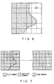
- the purpose of the second embodiment is to simultaneously remove not only block distortions but also mosquito noise appearing noticeably particularly near the edge of the image shown by dark dots in FIG. 6.
- the inputted code string 231 is a code string obtained at a video encoding apparatus and is decoded by a decoder 201 to reproduce a decoded picture signal 232.
- the decoded picture signal 232 is inputted to an edge/flat domain decision unit 209 and a displacement unit 211.
- the decoded picture signal 232 inputted to the edge/flat domain decision unit 209 is first divided by a segmentation unit 202 into a plurality of small blocks.
- An image quality decision unit 203 classifies these small blocks into flat domains and nonflat domains.
- an edge block decision unit 206 decides that the nonflat domains adjacent to the domains decided to be flat domains at the picture quality decision unit 203 are blocks (edge blocks) containing the edges.
- the picture quality decision unit 203 outputs a flat domain decision signal 237.
- the processing algorithm of the picture quality decision unit 203 and edge block decision unit 206 is shown below.
- Step 2 Classify the individual blocks into flat domains and nonflat domains according to the values of the blocks.
- Step 3 Decide the nonflat domains adjacent to flat domains to be edge portions (edge blocks).
- FIG. 7 shows this situation.
- the blocks containing the edges forming the outline of the picture on the left of the figure are nonflat domains adjacent to flat domains, so the blocks are decided to be edge blocks.
- an edge decision unit 207 separates the blocks decided by the edge block decision unit 206 to be edge blocks into the domains continuing from the flat domains adjacent to the edge blocks and the other domains.
- the pixels having a luminance in the range of a specific value from the DC components of the luminance of the flat domains adjacent to the edge blocks are decided to be the domains continuous with the flat domains and are separated from the remaining domains.
- the edge decision unit 207 outputs edge decision signals 236 and 238.
- an edge portion displacement unit 208 takes the average of the pixel values in the domains decided to be domains continuous with the flat domain blocks among the blocks decided by the edge decision unit 207 to be edge portions, for each of the blocks divided by the segmentation unit 210, on the basis of the edge decision signal 236 from the edge decision unit 207.
- the edge portion displacement unit uses the average value as the representative average value (DC component) for all of the edge blocks, which is substituted for the decoded picture signal 232 of the block.
- the AC component predictor 204 performs AC component prediction on the picture signal 239 whose edge blocks have been replaced by the edge portion displacement unit 208, thereby producing an AC component prediction picture signal 233.
- a switch 205 substitutes the AC component prediction picture signal 233 from the AC component predictor 208 for the blocks decided by the picture quality decision unit 203 to be flat domains and the blocks decided by the edge decision unit 207 to be edge blocks, on the basis of the flat domain decision signal 237 from the picture quality decision unit 203 and the edge decision signal 238 from the edge decision unit 207.
- the switch then outputs the resulting signal.
- the switch outputs the decoded picture signal 232 as it is.
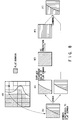
- the edge decision unit 207 separates edge block (shown at (b) in FIG. 8) in picture (shown at (a) in FIG. 8) into a first region in the upper part and a second region in the lower part.
- the edge displacement unit 208 substitutes the average of the pixel values in the first region for the entire edge block (shown at (b) in FIG. 8) as shown by region (shown at (d) in FIG. 8).
- the AC component predictor 204 performs AC component prediction as shown by region (shown at (e) in FIG. 8).
- the signal whose AC components have been predicted in region (shown at (e) in FIG. 8) is combined with the signal in the nonflat domain discontinuous with the adjacent flat domain in the lower part of region (shown at (c) in FIG. 8), as shown by region (shown at (f) in FIG. 8), thereby preserving information on the edge portion.
- the activity (dispersion) of the image is used as an index for judging whether a region is a flat domain or a nonflat domain
- the present invention is not restricted to this.
- Various decision methods may be used. According to each of the various decision methods, the flat domain decision unit 129 may be constructed suitably.
- the edge deciding method is such that the pixel value (luminance) of the picture signal is simply examined and a portion differing from the adjacent pixel by a specific value or more is decided to be an edge portion.
- Other various edge deciding methods may be used.
- the edge/flat domain decision unit 209 may be constructed suitably.
- the displacement unit 211 is composed of the segmentation unit 210 and edge portion displacement unit 208 according to the AC component prediction scheme, this configuration is not necessarily followed. If division into small domains is not necessary, a method of replacing the nonflat domains with the signals in the flat domains on the entire screen, instead of replacement on a small domain basis, may be used.
- the picture signal inputted from a camera 302 provided on a personal computer (PC) 301 is coded by a video encoding apparatus built in the PC 301.
- the coded data outputted from the video encoding apparatus is multiplexed with other audio information and data and then is transmitted by a radio transceiver 303 and is received by another radio transceiver 304.
- the signal received by the radio transceiver 304 is separated into the coded data of the picture signal and the audio signal and data.
- the coded data of the picture signal is decoded by the video decoding apparatus built in a workstation (EWS) 305 and the decoded signal is allowed to appear on the display of the EWS 305.
- EWS workstation
- the picture signal inputted from a camera 306 provided on the EWS 305 is coded by a video encoding apparatus built in the EWS 305 as described above.
- the coded data of the picture signal is multiplexed with other audio signal and data and then is transmitted by the radio transceiver 304 and is received by the radio transceiver 303.
- the signal received by the radio transceiver 303 is separated into the coded data of the picture signal and the audio signal and data.
- the coded data of the picture signal is decoded by the video decoding apparatus built in the PC 301 and the decoded signal is allowed to appear on the display of the PC 301.
- FIG. 10 is a schematic block diagram of the video encoding apparatus and video decoding apparatus built in the PC 301 and EWS 305, respectively.
- the video encoding apparatus of FIG. 10 comprises a data source encoding section 312 that includes an error resilience processor 313 and receives the picture signal from a video input section 311, such as a camera, and a transmission line encoding section 314.
- the data source encoding section 312 provides discrete cosine transform (DCT) of the prediction error signal and quantizes the produced DCT coefficients.
- the transmission line encoding section 314 performs variable-length coding, senses errors in the coded data, and produces error-correcting code.
- the coded data outputted from the transmission line encoding section 314 is transmitted to a radio transceiver 315, which transmits it.
- the video decoding apparatus of FIG. 10 comprises a transmission line decoding section 312 that receives the coded data received by a radio transceiver 321 and carries out the opposite process to that of the transmission line encoding section 314 and a data source decoding section 323 that includes an error resilience processor 324 for carrying out the opposite process to that of the data source encoding section 312 and receives the output signal of the transmission line decoding section 321.
- the picture decoded by the data source decoding section 323 is outputted by a video output section 325, such as a display.
- visual high-quality decoded pictures can be obtained by reducing block distortions in the decoded picture signal caused in coding the picture signal and distortions, such as mosquito noise, caused during quantization.
- FIG. 11 shows the configuration of an encoding distortion reducer in an image processing apparatus according to a third embodiment of the present invention.
- the encoding distortion reducer receives the decoded picture signal 421 as an input picture signal from the video decoding apparatus and causes a time-domain adaptive filter 400 to perform a filtering process (hereinafter, referred to as a time filtering process) on the decoded picture signal 421 within time-domain, and outputs an output picture signal 423.
- a time filtering process hereinafter, referred to as a time filtering process
- the time-domain filter 400 is composed of a first multiplier 401, an adder 402, a frame delay circuit 403, and a second multiplier 404.
- the filter coefficient (hereinafter, referred to as the weight coefficient) of the time-domain filter 400 is determined by a weight coefficient decision section 405.
- the weight coefficient decision section 405 is composed of an inter-frame difference calculator 406 and a weight coefficient calculator 407.
- the inputted decoded picture signal 421 is multiplied at the first multiplier 401 by a first weight coefficient 425 outputted from the weight coefficient decision section 405, and the resulting signal is inputted to the adder 402.
- the output signal from the adder 402 is outputted as an output picture signal 423 to the outside world and is also inputted to the frame delay circuit 403.
- the frame delay circuit 403 outputs a signal 424 obtained by delaying the output picture signal 423 for one frame.
- the output signal 424 from the frame delay circuit 403 is multiplied at the second multiplier 404 by a second weight coefficient 426 outputted from the weight coefficient decision section 405.
- the output signal from the second multiplier 404 is added to the output signal from the first multiplier 401 at the adder 402.
- the weight coefficient decision section 405 determines weight coefficients 425, 426 pixel by pixel as shown below, on the basis of the decoded picture as shown below, on the basis of the decoded picture signal 421 and the output picture signal 424 of the previous frame.
- the inter-frame difference calculator 406 computes the amount D of the difference between the decoded picture signal 421 and the output picture signal 424 of the preceding frame according to the following equation using pixels in the range of ⁇ M from the pixels to be processed:
- the weight coefficient calculator 407 calculates and determines a weight coefficient.
- FIG. 12 shows an example of the relationship between the amount D of the difference and the weight coefficient.
- W on the vertical axis indicates the second weight coefficient 426.
- the first weight coefficient 425 is determined to be (1 - W).
- ath1, ath2, and WL are predetermined constants.
- the weight coefficient decision section 405 determines the weight coefficients adaptively according to the amount D of the difference between the decoded picture signal 421 and the output picture signal 424 of the previous frame. That is, when the amount D of the difference is small, the weight coefficient decision section makes a determination so that W may be large. This prevents the decoded picture signal 421 added with encoding distortions from being outputted directly for the still portions where encoding distortions tend to be conspicuous. Instead, the time-domain filter 400 performs a time filtering process on the decoded picture signal 421 through weighting addition with the output picture signal 424 of the previous frame. The resulting signal is then outputted as the output picture signal 424, thereby alleviating encoding distortions.
- processing is carried out in pixels, the processing may be performed in blocks.
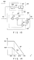
- FIG. 13 is a block diagram of an encoding distortion reducer, which is a picture signal processing apparatus according to a fourth embodiment of the present invention.
- the relationship between the amount D of the difference and the weight coefficient W is changed according to, for example, the largeness of the motion vector detected by the video encoding apparatus.
- a signal (referred to as a side information signal) 428 indicating the encoding mode and motion vector is inputted to the weight coefficient calculator 407 in the filter coefficient decision section 405, in addition to the decoded picture signal 421 from the video decoding apparatus.
- FIG. 14 shows an example of switching the relationship between the amount D of the difference and the weight coefficient W between the portions subjected to refresh coding and the other portions, when the video encoding apparatus performs refresh coding to suppress the propagation of picture quality deterioration caused by errors in the transmission channel.
- the characteristic indicated by 501 is used for the portions subjected to refresh coding and the characteristic indicated by 502 is used for the other portions.
- the encoding mode for the portions subjected to refresh coding is the intra-frame encoding mode, so the nature of the decoded picture is different because the encoding method differs from the encoding mode in the other portions (e.g., the motion compensation prediction encoding mode), with the result that the decoded picture tends to be unnatural.
- the weight coefficient W that is, the weight coefficient 426 for the output picture signal 424 of the previous frame
- the weight coefficient W becomes larger in the still portions where the amount D of the difference gets smaller or the portions where motion is small. Therefore, of the decoded video signal 421, the portion where the nature has changed due to refresh coding is subjected to weighting addition with the output picture signal 424 of the previous frame, which thereby performs the time filtering process strongly on that portion, minimizing the deterioration of the picture quality.
- FIG. 15 shows another example of relationship between the amount D of the difference and the weight coefficient W in the embodiment.
- the characteristic 601 that the weight coefficient W becomes larger is used.
- the use of the characteristic 601 suppresses encoding distortions caused by an erroneous motion vector at the boundary between the still portion and the moving object. This helps reduce encoding distortions especially in patch motion compensation that is liable to cause large distortions at the boundary of the object.
- FIG. 16 is a block diagram of an encoding distortion breducer, which is a picture signal processing apparatus according to a fifth embodiment of the present invention.
- the relationship between the amount D of the difference and the weight coefficient W is changed according to the activity representing the complexity of a picture.
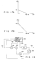
- a filter coefficient decision section 405 is such that an activity calculator 408 computes the activity of the decoded picture signal 421 and a threshold calculator 409 produces threshold values athl and ath2 of FIGS. 17A and 17B so that the threshold values may change according to the calculated activity.
- the activity calculator 408 and inter-frame difference calculator 406 compute the activity 431 of the decoded picture signal 421 and the amount 427 of the difference between the decoded picture signal and the output picture signal 424 of the previous frame according to the following equation using pixels in the range of ⁇ M from the pixels to be processed:
- the threshold calculator 409 determines a first threshold 432 (athl) and a second threshold value 433 (ath2) from the activity 221 on the basis of the characteristics in FIGS. 17A and 17B.
- th1, th2, and ⁇ are predetermined constants.
- the weight coefficient calculator 407 determines weight coefficients 425 and 426 according to the characteristic shown in FIG. 12 on the basis of the amount 427 of the difference and the first and second threshold values 432 and 433.
- the threshold values ath1 and ath2 become smaller and the weight coefficient W gets smaller in the portions where the activity is high, that is, at the edges and the portions where the pattern is fine. This reduces the intensity of time filtering at the time-domain filter 400, which helps minimize the blurring of the picture caused by the time filter.
- FIG. 18 is a block diagram of an encoding distortion reducer, which is a picture signal processing apparatus according to a sixth embodiment of the present invention.
- the corresponding parts to those in FIG. 11 are indicated by the same reference symbols.
- the sixth embodiment differs from the third embodiment in that an additional spatial filter 410 is used and the output signal of the adder 402 undergoes an encoding distortion reducing process with respect to spatial at the spatial filter 410 and thereafter the resulting signal is outputted as an output picture signal 423.
- the spatial filter 410 removes encoding distortions by performing the filtering process with respect to spatial domain. Specifically, for example, the spatial filter changes the intensity of filtering adaptively according to the amount of the difference between adjacent pixels in such a manner that it makes the filtering more intense for a smaller difference between pixels and less intense for a larger difference between pixels. This makes it possible to remove encoding distortions, including mosquito distortions, while preserving the edges.
- the present embodiment by combining the removal of encoding distortions with respect to time by the time-domain filter 400 with the removal of encoding distortion with respect to the spatial filter, an afterimage seldom occurring as a result of the weighting addition of the output picture signal 424 delayed one frame from the decoded picture signal 421 can be removed, improving the quality of the output picture signal 423 as compared with use of the time filter only.
- FIG. 19 is a block diagram of an encoding distortion reducer, which is a picture signal processing apparatus according to a seventh embodiment of the present invention.
- the encoding distortion reducer receives the decoded picture signal 451 of the present frame inputted from the video decoding apparatus and the decoded picture signal 454 of the previous frame stored in the frame memory of the video decoding apparatus, causes a noncyclic-domain adaptive filter 440 to perform the encoding distortion removing process, and outputs an output picture signal 453.
- the time filter 440 is composed of a first multiplier 441, an adder 442, and a second multiplier 444.
- the filter coefficient (called the weight coefficient) of the time filter 440 is determined by the weight coefficient decision section 445.
- the first and second multipliers 441, 444 multiply the decoded picture signal 451 of the inputted present frame and the decoded picture signal 458 of the previous frame by the first and second weight coefficients supplied from the weight coefficient decision section 445, respectively.
- the resulting signals are inputted to the adder 442, which adds them.
- the output signal of the adder 442 is outputted as an output picture signal 453 from the present picture processing apparatus to an external apparatus.
- the weight coefficient decision section 445 determines weight coefficients in the same manner as the weight coefficient decision section 405 in each of the first to fourth embodiments.
- the inter-frame difference D is calculated as the difference between the decoded picture signal 451 and the decoded picture signal 454 of the previous frame using the following equation: where
- the noncyclic time filter 440 performs the encoding distortion reducing process in place of the time-domain adaptive filter 400 used in the third to sixth embodiments. Therefore, although the performance of removing encoding distortions is a little lower than that in the third to sixth embodiments, an afterimage occurring as a result of the weighting addition of the output picture signal of the previous frame and the decoded picture signal of the present frame is minimized differently from the third to sixth embodiments. Furthermore, in the seventh embodiment, the decoded picture signal 454 of the previous frame is received from the video decoded apparatus, so a frame delay circuit need not be provided in the encoding distortion reducer, reducing the amount of hardware.
- the decoded picture signal 454 of the previous frame may not be outputted.
- a frame delay circuit 443 that delays the decoded picture signal 451 of the present frame for one frame in time is provided in the encoding distortion reducer to produce the decoded picture signal 454 of the previous frame.
- FIG. 20 is a block diagram of a picture signal processing apparatus according to an eighth embodiment of the present invention. Unlike the third to seventh embodiments, the eighth embodiment is such that the video encoding apparatus suppresses noise and flicker before the compression coding of the picture signal.
- An input picture signal 471 is supplied to an black-level picture boundary removing section 466, which removes from the picture signal the black level pixels existing at the boundary of the picture produced by a camera input problem, that is, the pixel signals of low-level pixels whose pixel values are smaller than a specific threshold value.
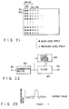
- FIG. 21 is a drawing to help explain the image black edge removing process.
- the figure shows an example of the process of removing black-level pixels existing at the left end of the image.
- black circles represent black-level pixels and white circles represent pixels other than black-level pixels.
- Step 1 First, sense black-level pixels, starting from the left end of the picture. A determination whether a pixel is of black level is made by checking if the pixel value is equal to or smaller than a predetermined threshold value
- Step 2 determine how many black-level pixels continue from the left end of the picture for each horizontal line. Determine the number of black-level pixels from the left end of the picture thus obtained to be Nsb.
- Step 3 replace the pixel signal of a black-level pixel with the pixel signal of the pixel located Nf (a given integer) pixels on the right of the black-level pixel.
- the time-domain adaptive filter 460 removes noise and flicker from the picture signal subjected to the process of removing the pixel signals of black-level pixels existing at the boundary of the picture at the black level picture boundary removing section 466.
- the time-domain adaptive filter 460 and the weight coefficient decision section 465 that determines the filter coefficient (weight coefficient) of the time-domain adaptive filter have the same configurations as those in the third to sixth embodiments.
- a multiplier 461, an adder 462, a frame delay circuit 463, and a multiplier 464 function in the same manner as the multiplier 401, adder 402, frame delay circuit 403, and multiplier 404 in FIG. 11. delay circuit 403, and multiplier 404 in FIG. 11.
- a weight coefficient section 465 determines a weight coefficient in the same manner as the third to sixth embodiments. It is assumed, however, that the constants including Wl, thl, th2, a, etc. are determined according to the nature of the input picture signal 471 or the picture signal obtained by causing the input picture signal to pass through the black-level picture boundary removing section 466.
- inter-frame difference D and activity act are found from the sum of absolute values, they may be calculated using square-sum, weighted absolute value sum, or weighted square-sum.
- wa and W D are coefficients that give weight according to k and 1.
- the image processing apparatus of the present invention it is possible to reduce encoding distortions produced during the compression coding of the picture signal and thereby improve the quality of the decoded picture.
- the compression coding efficiency is increased by reducing noise, flicker, and black edges existing in the picture signal to be subjected to compression coding, thereby improving the encoding quality.
- FIG. 22 shows an image processing apparatus according to a ninth embodiment of the present invention.
- an input terminal 811 is connected to the input of a segmentation circuit 812.
- the output of the segmentation circuit 812 is connected to the input of a filter controller 813 and the input of a filter 814.
- the signal obtained by decoding and decompressing the compression-coded picture signal into the original picture signal, is inputted to the input terminal 811.
- the segmentation circuit 812 has the function of dividing the picture signal inputted from the input terminal 811 into square blocks of the same size as that in DCT coding and outputting these blocks.
- the filter controller 813 receives the picture signal divided into blocks from the segmentation circuit 812, checks for a change in the density of pixels in a block, recognizes whether the change is gentle, is sharp, or includes small changes, finds the controlled value for the corresponding filter process, and output the controlled value as a control signal S.
- the filter 814 is a digital filtering section that receives the control signal S from the filter controller 813 and set the filtering process and that receives the picture signal divided into blocks from the segmentation circuit 812 and performs the filtering process corresponding to the control signal S, and outputs the resulting signal.
- the apparatus thus constructed operates as follows. An image signal whose picture quality has deteriorated due to encoding is inputted to the input terminal 811. The image signal whose picture quality has deteriorated due to encoding inputted from the input terminal 811 is first inputted to the segmentation circuit 812, which then divides the picture signal into small blocks. The small blocks thus divided are of the same square size as in DCT coding. The picture signal divided into blocks are inputted to the filter controller 813 and filter 814.
- the filter controller 813 senses the maximum value Pmax and minimum value Pmin in the pixel values in the block and finds the difference PDFf between the maximum value Pmax and minimum value Pmin.
- the filter controller 813 converts the calculated difference PDFf between the maximum value and minimum value into a control signal S that controls the intensity of smoothing of the filter 814 and supplies the control signal to the filter 814.
- the difference PDFf between the maximum value Pmax and minimum value Pmin is compared with a setting value a (e.g., about 4).
- a setting value a e.g., about 4
- S is determined to be, for example, 0.5.
- the value of 0.5 is outputted as control signal S , which is supplied to the filter 14.
- the setting value a was set at 4 and the value of control signal S was set at 0.5, which were experimental values. With these values, the satisfied result was obtained.
- the setting value and the value of control signal S are set to the optimum values, regardless of the above values, taking into account the filter effect actually produced.
- a signal shown in FIG. 25 is taken as example.
- the signal with a small amplitude is not an encoding distortions but a texture included in the original picture.
- the average of the pixel values in the block is determined to be 0 and the number of zero-crossings of the video data (data value) is counted in order not to lose fine textures.
- NZC the number of zero-crossings of the video data
- S (Pmax - Pmin)/(255(b + NZC)) where b is a constant.
- the b is set at about 20, which is an experimental value. This value produced a good result.
- another value may be better, so the optimum value may be selected by actually trying various values according to a filter to be used.
- the fine texture screen can be given a control signal S that makes smoothing less intense according to the fineness by such calculations.
- the filter controller 14 is provided with the function of counting the number of zero-crossings of the picture signal (data value) and determining on the basis of the resulting count whether the result of the second control signal acquisition process or the first control signal acquisition process is determined to be output control signal.
- control function may be such that the result of the first control signal acquisition process is mixed with the second control signal acquisition process with a specific ratio according to the count.
- the control signal S thus obtained at the filter controller 813 is sent to the filter 11, which performing the smoothing process on the picture signal obtained from the input terminal 811, while changing the intensity of smoothing according to the control signal S .
- the decoded picture signal whose picture quality has deteriorated due to encoding is checked for a change in the density between pixels in the block size in the DCT processing during encoding. Then, a control signal for performing the optimum filtering according to the density change is found. With the intensity corresponding to the magnitude of the control signal S, smoothing is effected. The resulting signal is outputted at the output terminal 815.
- One method of changing the intensity of smoothing of the filter is a method of mixing the filtered signal with the unfiltered signal with the ratio corresponding to the value of the control signal S .
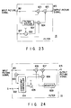
- FIG. 23 shows the configuration of the filter 814 to which the above method is applied.
- the filter is composed of a filter section 822 that performs intense smoothing, multipliers 323, 324, an adder 825, and a subtracter 828.
- An input terminal 821 receives the decoded blocked picture signal from the segmentation circuit 812.
- An output terminal 815 outputs the filtered picture signal.
- An input terminal 827 is an input terminal for control signal S .
- the filter section 822 filters the picture signal from the input terminal 821.
- the subtracter 828 subtracts the control signal S from the input terminal 827 from "1.”
- the multiplier 823 multiplies the picture signal from the input terminal 821 by the subtraction result from the subtracter 828.
- the multiplier 824 multiplies the output of the filter section 822 by the control signal S from the input terminal 827.
- the adder 825 adds the output of the multiplier 823 to the output of the multiplier 824 and outputs the result to the output terminal 815.
- the segmented picture signal, or the output of the segmentation circuit 821 is supplied from the input terminal 821.
- the control signal S the output of the filter controller 813, is supplied from the input terminal 827.
- the picture signal supplied from the input terminal 821 is inputted to the filter section 822, which effects the intense filtering of the picture signal.
- the picture filtered and outputted from the filter section 822 is a picture that has undergone the most intense smoothing process set in the filter.
- control signal S the output of the filter controller 813, supplied from the input terminal 827 is inputted to the subtracter 828.
- the subtracter is given "1" as a value from which a certain value is to be subtracted.
- the subtracter 828 subtracts the control signal S from "1" and determines the difference to be the mixing ratio of the unfiltered signal.
- the picture signal from the input terminal 821 is also supplied to the multiplier 823, which multiples the picture signal by (1 - S), which is the mixing ratio of the unfiltered signal obtained at the subtracter 828.
- the multiplication result is given to the adder 825.
- the control signal S the output of the filter controller 813, supplied from the input terminal 827 is also supplied as a multiplicator to the multiplier 824, to which the filtered picture signal is supplied as a multiplicand from the filter section 822.
- the multiplier 824 multiplies the control signal S by the filtered picture signal and supplies the resulting signal to the adder 825. If the control signal takes a value in the range from 1 to 0, the multiplication result of the multiplier 824 corresponds to the mixing ratio of the control signal S to the filtered signal.
- the adder 825 adds the output of the multiplier 824 to the output of the multiplier 823 and the resulting signal is outputted at the output terminal 815.
- the output of the adder 825 that adds the output of the multiplier 824 to the output of the multiplier 823 is a picture signal obtained by mixing the filtered picture signal with the unfiltered picture signal with the mixing ratio determined by the control signal S. Therefore, a space filter that performs filtering with the intensity of smoothing corresponding to the control signal S is obtained.
- Another method of constructing a filter 814 capable of changing the intensity of smoothing is to use a cyclic variable weight coefficient filter. With this method, the intensity of the filter is controlled in pixels, so only encoding distortions can be smoothed, with the edge being preserved.
- the cyclic variable weight coefficient filter will be explained.
- the filter is composed of difference units 833 and 835, a coefficient controller 834, multipliers 836 and 837, an adder 837, and a register 839.
- An input terminal 831 receives the segmented picture signal or the output of the segmentation circuit 812.
- An input terminal 832 receives the control signal S from the filter controller 813.
- the control signal S is supplied via the input terminal 832 to the coefficient controller 834.
- the filtered picture signal is outputted at the output terminal 815.
- the register 839 holds the filtered picture signal temporarily.
- the register receives the output of the adder 837 pixel by pixel and updates and holds these pixels.
- the difference unit 833 calculates the difference between the picture signal (in pixels) from the input terminal 831 and the picture signal (the pixels before one pixel) held in the register 839.
- the coefficient controller 834 receives the difference and control signal S , carries out specific calculations, and finds the weight coefficient C of the pixels.
- the difference unit 835 subtracts the weight coefficient C computed at the coefficient controller 834 from "1."
- the multiplier 836 multiplies the picture signal from the input terminal 831 by the value found at the difference unit 835.
- the multiplier 838 multiplies the picture signal held in the register 839 by the weight coefficient C obtained by the coefficient controller 834.
- the adder 837 adds the output of the multiplier 836 to the output of the multiplier 838.
- the segmented picture signal is supplied from the input terminal 831 to the weight coefficient controller 834.
- the output signal S of the filter controller 813 is supplied from the input terminal 832 to the weight coefficient controller 834.
- the difference D between the input picture signal and the processed pixel value before one pixel is computed at the difference unit 833.
- the difference D is also supplied to the weight coefficient controller 834.
- the multiplier 836 multiplies the input picture signal by the difference from the weight coefficient C ((input picture signal)*(1 - C)).
- the multiplier 838 multiplies the processed pixel value before one pixel by weight coefficient C.
- the adder 837 adds the output of the multiplier 836 to the output of the multiplier 838.
- the resulting signal is outputted at the output terminal 815.
- the addition result is stored in the register 839 and is used as a preprocessing pixel value. Therefore, a space filter that performs filtering in pixels with the intensity of smoothing corresponding to the control signal S is obtained.
- the apparatus of the present invention comprises a circuit unit for dividing an input picture signal into a plurality of blocks, a filter controller that computes the difference between the maximum and minimum of the pixel values in the block, make smoothing more intense as the difference between the maximum value and the minimum value, and produces a signal that makes smoothing more intense when the difference between the maximum and minimum values is smaller than a setting value, and filtering means (a space filter for smoothing) that filters the input picture signal, while changing the intensity of smoothing according to the signal of the filter controller.
- filtering means a space filter for smoothing
- the apparatus of the invention comprises a circuit that divides the input picture signal into a plurality of regions corresponding to the divided blocks at the time of orthogonal transform in the encoding process, filter control means that counts the number of zero-crossings in a case where the average value of the region is determined to be 0, or the number of maximal values, or the number of minimal values, and produces a signal that makes smoothing less intense as the number of zero-crossings, the number of maximal values, or the number of minimal values, and a filter circuit that changes the intensity of smoothing according to the signal from the filter controller.
- the present invention is not limited to the above embodiments, for instance, by limiting the contents of control which the filter controller 813 that finds the controlled value of smoothing degree from the pixel density is supposed to do, a filter unit designed for a single effect, such as reducing only block distortions or mosquito noise, is achieved.
- the degree of encoding distortions varies with the local characteristic of the picture.
Landscapes
- Engineering & Computer Science (AREA)
- Multimedia (AREA)
- Signal Processing (AREA)
- Compression Or Coding Systems Of Tv Signals (AREA)
Applications Claiming Priority (9)
| Application Number | Priority Date | Filing Date | Title |
|---|---|---|---|
| JP28091095 | 1995-10-27 | ||
| JP28091095A JP3800435B2 (ja) | 1995-10-27 | 1995-10-27 | 動画像信号処理装置 |
| JP280912/95 | 1995-10-27 | ||
| JP28091295A JPH09130791A (ja) | 1995-10-27 | 1995-10-27 | 画像処理装置 |
| JP28091295 | 1995-10-27 | ||
| JP28076995 | 1995-10-27 | ||
| JP28076995A JPH09130797A (ja) | 1995-10-27 | 1995-10-27 | 画像処理装置および画像処理方法 |
| JP280910/95 | 1995-10-27 | ||
| JP280769/95 | 1995-10-27 |
Publications (2)
| Publication Number | Publication Date |
|---|---|
| EP0771116A2 true EP0771116A2 (de) | 1997-05-02 |
| EP0771116A3 EP0771116A3 (de) | 1999-07-14 |
Family
ID=27336771
Family Applications (1)
| Application Number | Title | Priority Date | Filing Date |
|---|---|---|---|
| EP96307722A Withdrawn EP0771116A3 (de) | 1995-10-27 | 1996-10-25 | Bildverarbeitungsvorrichtung |
Country Status (2)
| Country | Link |
|---|---|
| US (1) | US6064776A (de) |
| EP (1) | EP0771116A3 (de) |
Cited By (3)
| Publication number | Priority date | Publication date | Assignee | Title |
|---|---|---|---|---|
| EP0808068A3 (de) * | 1996-05-14 | 1998-05-06 | Daewoo Electronics Co., Ltd | Reduzierung von Blockeffekten in einem Bewegtbilddekoder |
| WO2008140679A1 (en) | 2007-05-11 | 2008-11-20 | Raritan Americas, Inc. | Methods for adaptive video quality enhancement |
| CN103795943A (zh) * | 2012-11-01 | 2014-05-14 | 富士通株式会社 | 图像处理装置和图像处理方法 |
Families Citing this family (52)
| Publication number | Priority date | Publication date | Assignee | Title |
|---|---|---|---|---|
| US6408029B1 (en) | 1998-04-02 | 2002-06-18 | Intel Corporation | Method and apparatus for simplifying real-time data encoding |
| US6904174B1 (en) * | 1998-12-11 | 2005-06-07 | Intel Corporation | Simplified predictive video encoder |
| JP4027513B2 (ja) * | 1998-09-29 | 2007-12-26 | 株式会社ルネサステクノロジ | 動き検出装置 |
| KR100366643B1 (ko) * | 1998-11-25 | 2003-02-19 | 삼성전자 주식회사 | 구획현상제거방법및장치 |
| US7015979B1 (en) * | 1999-11-24 | 2006-03-21 | Intel Corporation | Noisy edge removal for video transmission |
| WO2002102086A2 (en) * | 2001-06-12 | 2002-12-19 | Miranda Technologies Inc. | Apparatus and method for adaptive spatial segmentation-based noise reducing for encoded image signal |
| US6983079B2 (en) * | 2001-09-20 | 2006-01-03 | Seiko Epson Corporation | Reducing blocking and ringing artifacts in low-bit-rate coding |
| US7031549B2 (en) * | 2002-02-22 | 2006-04-18 | Hewlett-Packard Development Company, L.P. | Systems and methods for enhancing tone reproduction |
| US7639741B1 (en) * | 2002-12-06 | 2009-12-29 | Altera Corporation | Temporal filtering using object motion estimation |
| EP1480170A1 (de) * | 2003-05-20 | 2004-11-24 | Mitsubishi Electric Information Technology Centre Europe B.V. | Verfahren und Gerät zur Bildverarbeitung |
| US7471726B2 (en) * | 2003-07-15 | 2008-12-30 | Microsoft Corporation | Spatial-domain lapped transform in digital media compression |
| US7724827B2 (en) * | 2003-09-07 | 2010-05-25 | Microsoft Corporation | Multi-layer run level encoding and decoding |
| US7616829B1 (en) * | 2003-10-29 | 2009-11-10 | Apple Inc. | Reducing undesirable block based image processing artifacts by DC image filtering |
| FR2872664A1 (fr) * | 2004-07-01 | 2006-01-06 | Nextream France Sa | Dispositif et procede de pre-traitemebnt avant codage d'une sequence d'images video |
| US7860167B2 (en) * | 2004-07-30 | 2010-12-28 | Algolith Inc. | Apparatus and method for adaptive 3D artifact reducing for encoded image signal |
| US7724979B2 (en) * | 2004-11-02 | 2010-05-25 | Broadcom Corporation | Video preprocessing temporal and spatial filter |
| EP2002653A2 (de) * | 2004-12-08 | 2008-12-17 | Imagine Communications Ltd., | Verteiltes statistisches multiplexen von multimedia |
| US7428342B2 (en) * | 2004-12-17 | 2008-09-23 | Microsoft Corporation | Reversible overlap operator for efficient lossless data compression |
| US7471850B2 (en) * | 2004-12-17 | 2008-12-30 | Microsoft Corporation | Reversible transform for lossy and lossless 2-D data compression |
| US8036274B2 (en) * | 2005-08-12 | 2011-10-11 | Microsoft Corporation | SIMD lapped transform-based digital media encoding/decoding |
| US8004606B2 (en) * | 2005-09-08 | 2011-08-23 | Silicon Image, Inc. | Original scan line detection |
| US8120703B2 (en) * | 2005-09-08 | 2012-02-21 | Silicon Image/BSTZ | Source-adaptive video deinterlacer |
| US7982798B2 (en) * | 2005-09-08 | 2011-07-19 | Silicon Image, Inc. | Edge detection |
| US7787541B2 (en) * | 2005-10-05 | 2010-08-31 | Texas Instruments Incorporated | Dynamic pre-filter control with subjective noise detector for video compression |
| US20070116117A1 (en) * | 2005-11-18 | 2007-05-24 | Apple Computer, Inc. | Controlling buffer states in video compression coding to enable editing and distributed encoding |
| US8031777B2 (en) * | 2005-11-18 | 2011-10-04 | Apple Inc. | Multipass video encoding and rate control using subsampling of frames |
| US8780997B2 (en) * | 2005-11-18 | 2014-07-15 | Apple Inc. | Regulation of decode-side processing based on perceptual masking |
| US8233535B2 (en) * | 2005-11-18 | 2012-07-31 | Apple Inc. | Region-based processing of predicted pixels |
| US8295343B2 (en) | 2005-11-18 | 2012-10-23 | Apple Inc. | Video bit rate control method |
| KR100627615B1 (ko) * | 2005-12-29 | 2006-09-25 | 엠텍비젼 주식회사 | 조정 가능한 임계값을 이용한 노이즈 제거 장치 |
| JP4747917B2 (ja) * | 2006-04-03 | 2011-08-17 | 株式会社日立製作所 | デジタル放送受信装置 |
| US8027383B2 (en) * | 2006-06-13 | 2011-09-27 | Lsi Corporation | Mosquito noise reduction filter in digital decoders |
| JP4747975B2 (ja) * | 2006-07-14 | 2011-08-17 | ソニー株式会社 | 画像処理装置および方法、プログラム、並びに、記録媒体 |
| US8086067B2 (en) * | 2006-12-20 | 2011-12-27 | Silicon Image, Inc. | Noise cancellation |
| JP4875007B2 (ja) * | 2007-02-09 | 2012-02-15 | パナソニック株式会社 | 動画像符号化装置、動画像符号化方法、及び、動画像復号化装置 |
| US8305497B2 (en) * | 2007-07-27 | 2012-11-06 | Lsi Corporation | Joint mosquito and aliasing noise reduction in video signals |
| EP2051524A1 (de) * | 2007-10-15 | 2009-04-22 | Panasonic Corporation | Bildverbesserung unter Berücksichtigung des Prediktionsefehlers |
| US8369638B2 (en) | 2008-05-27 | 2013-02-05 | Microsoft Corporation | Reducing DC leakage in HD photo transform |
| US8447591B2 (en) * | 2008-05-30 | 2013-05-21 | Microsoft Corporation | Factorization of overlapping tranforms into two block transforms |
| US8559746B2 (en) * | 2008-09-04 | 2013-10-15 | Silicon Image, Inc. | System, method, and apparatus for smoothing of edges in images to remove irregularities |
| US8275209B2 (en) * | 2008-10-10 | 2012-09-25 | Microsoft Corporation | Reduced DC gain mismatch and DC leakage in overlap transform processing |
| TWI390467B (zh) * | 2009-01-23 | 2013-03-21 | Silicon Integrated Sys Corp | 動態雜訊濾波裝置及西格瑪濾波方法 |
| US8452117B2 (en) * | 2009-02-10 | 2013-05-28 | Silicon Image, Inc. | Block noise detection and filtering |
| KR101064883B1 (ko) * | 2009-10-06 | 2011-09-16 | 한국과학기술원 | 왜곡 측정 방법 |
| JP2011211474A (ja) * | 2010-03-30 | 2011-10-20 | Sony Corp | 画像処理装置および画像信号処理方法 |
| JP5367667B2 (ja) * | 2010-09-21 | 2013-12-11 | 株式会社東芝 | 画像処理装置 |
| TWI417690B (zh) | 2010-12-20 | 2013-12-01 | Ind Tech Res Inst | 控制系統 |
| JP5709996B2 (ja) | 2011-06-30 | 2015-04-30 | 三菱電機株式会社 | 画像復号装置及び画像復号方法 |
| WO2013081085A1 (en) * | 2011-11-28 | 2013-06-06 | Canon Kabushiki Kaisha | Moving image encoding apparatus, control method thereof and computer program |
| US9135683B2 (en) * | 2013-09-05 | 2015-09-15 | Arecont Vision, Llc. | System and method for temporal video image enhancement |
| JP6774813B2 (ja) * | 2016-08-12 | 2020-10-28 | 日本電子株式会社 | 画像処理装置、画像処理方法、および分析装置 |
| TWI680675B (zh) * | 2017-12-29 | 2019-12-21 | 聯發科技股份有限公司 | 影像處理裝置與相關的影像處理方法 |
Family Cites Families (5)
| Publication number | Priority date | Publication date | Assignee | Title |
|---|---|---|---|---|
| FR2589020B1 (fr) * | 1985-10-22 | 1987-11-20 | Eude Gerard | Procede de codage hybride par transformation pour la transmission de signaux d'image |
| US5146326A (en) * | 1989-11-14 | 1992-09-08 | Fujitsu Limited | Coded picture information decoding apparatus having means for improving picture distortion |
| US5229864A (en) * | 1990-04-16 | 1993-07-20 | Fuji Photo Film Co., Ltd. | Device for regenerating a picture signal by decoding |
| EP0585573A3 (en) * | 1992-08-31 | 1994-07-13 | Ibm | System and method for suppressing blocking artifacts in decoded transform coded images |
| JP2673778B2 (ja) * | 1994-02-22 | 1997-11-05 | 国際電信電話株式会社 | 動画像の復号化における雑音低減装置 |
-
1996
- 1996-10-24 US US08/740,125 patent/US6064776A/en not_active Expired - Lifetime
- 1996-10-25 EP EP96307722A patent/EP0771116A3/de not_active Withdrawn
Non-Patent Citations (1)
| Title |
|---|
| HIROSHI YASUDA: "The Standards for Multimedia Coding, Mazuren", June 1991 |
Cited By (6)
| Publication number | Priority date | Publication date | Assignee | Title |
|---|---|---|---|---|
| EP0808068A3 (de) * | 1996-05-14 | 1998-05-06 | Daewoo Electronics Co., Ltd | Reduzierung von Blockeffekten in einem Bewegtbilddekoder |
| EP1469680A3 (de) * | 1996-05-14 | 2005-10-05 | Daewoo Electronics Corporation | Reduzierung von Blockeffekten in einem Bewegtbilddekoder |
| WO2008140679A1 (en) | 2007-05-11 | 2008-11-20 | Raritan Americas, Inc. | Methods for adaptive video quality enhancement |
| EP2156677A4 (de) * | 2007-05-11 | 2011-01-26 | Raritan Americas Inc | Verfahren für adaptive verbesserung der videoqualität |
| US8582658B2 (en) | 2007-05-11 | 2013-11-12 | Raritan Americas, Inc. | Methods for adaptive video quality enhancement |
| CN103795943A (zh) * | 2012-11-01 | 2014-05-14 | 富士通株式会社 | 图像处理装置和图像处理方法 |
Also Published As
| Publication number | Publication date |
|---|---|
| US6064776A (en) | 2000-05-16 |
| EP0771116A3 (de) | 1999-07-14 |
Similar Documents
| Publication | Publication Date | Title |
|---|---|---|
| US6064776A (en) | Image processing apparatus | |
| US5565921A (en) | Motion-adaptive image signal processing system | |
| US5479211A (en) | Image-signal decoding apparatus | |
| KR100797807B1 (ko) | 코딩 아티팩트 감소 방법 | |
| USRE41446E1 (en) | Decoding apparatus including a filtering unit configured to filter an image by application of a weighted average operation | |
| EP0781053B1 (de) | Verfahren und Vorrichtung zur Nachbearbeitung von Bildern | |
| JP3678481B2 (ja) | 映像データ後処理方法 | |
| US5555028A (en) | Post-processing method and apparatus for use in an image signal decoding system | |
| EP0714210B1 (de) | Verfahren zum Vermindern von während einer Bilddatendekodierung erzeugtem Mückenrauschen und Vorrichtung zur Dekodierung von ein solches Verfahren verwendenden Bilddaten | |
| US6185254B1 (en) | Decoder, image encoding apparatus, image decoding apparatus, image transmitting method, and recording medium | |
| KR20010102155A (ko) | '블러키 화상' 효과의 감소 | |
| KR100229796B1 (ko) | 열화영상에 대한 보상기능을 갖는 영상 복호화 시스템 | |
| JP2001320713A (ja) | 画像予備処理方法 | |
| JP3209171B2 (ja) | 動画像符号化装置 | |
| US20060018386A1 (en) | Method for chroma deblocking | |
| JP3800435B2 (ja) | 動画像信号処理装置 | |
| JP3627291B2 (ja) | ブロック歪み除去装置および方法 | |
| JPH0710103B2 (ja) | 画像符号化伝送装置 | |
| JPH09130797A (ja) | 画像処理装置および画像処理方法 | |
| JPH0389792A (ja) | 画像符号化装置 | |
| JPH10164578A (ja) | 画像符号化復号化装置 | |
| JPH09130791A (ja) | 画像処理装置 | |
| JP2005260989A (ja) | 画像処理装置及び画像処理方法 | |
| Liu et al. | Hybrid DCT/quadtree motion-compensated coding of video sequences | |
| Somogyi et al. | A hierarchical coding scheme for digital distribution of progressively scanned HDTV signals |
Legal Events
| Date | Code | Title | Description |
|---|---|---|---|
| PUAI | Public reference made under article 153(3) epc to a published international application that has entered the european phase |
Free format text: ORIGINAL CODE: 0009012 |
|
| 17P | Request for examination filed |
Effective date: 19961120 |
|
| AK | Designated contracting states |
Kind code of ref document: A2 Designated state(s): DE FR GB |
|
| PUAL | Search report despatched |
Free format text: ORIGINAL CODE: 0009013 |
|
| AK | Designated contracting states |
Kind code of ref document: A3 Designated state(s): DE FR GB |
|
| 17Q | First examination report despatched |
Effective date: 20010323 |
|
| STAA | Information on the status of an ep patent application or granted ep patent |
Free format text: STATUS: THE APPLICATION IS DEEMED TO BE WITHDRAWN |
|
| 18D | Application deemed to be withdrawn |
Effective date: 20021011 |