EP0771128A2 - Procédé et circuit de compensation des erreurs de temporisation interne dans une station mobile - Google Patents
Procédé et circuit de compensation des erreurs de temporisation interne dans une station mobile Download PDFInfo
- Publication number
- EP0771128A2 EP0771128A2 EP96660064A EP96660064A EP0771128A2 EP 0771128 A2 EP0771128 A2 EP 0771128A2 EP 96660064 A EP96660064 A EP 96660064A EP 96660064 A EP96660064 A EP 96660064A EP 0771128 A2 EP0771128 A2 EP 0771128A2
- Authority
- EP
- European Patent Office
- Prior art keywords
- signal
- mobile station
- timing
- unit
- ave
- Prior art date
- Legal status (The legal status is an assumption and is not a legal conclusion. Google has not performed a legal analysis and makes no representation as to the accuracy of the status listed.)
- Granted
Links
Images


Classifications
-
- H—ELECTRICITY
- H04—ELECTRIC COMMUNICATION TECHNIQUE
- H04W—WIRELESS COMMUNICATION NETWORKS
- H04W56/00—Synchronisation arrangements
- H04W56/0035—Synchronisation arrangements detecting errors in frequency or phase
Definitions
- the present invention concerns a method in accordance with the preamble of claim 1 for compensating timing errors of a mobile station, particularly those of a digital mobile station.
- the invention also concerns a circuitry in accordance with the preamble of claim 7 for compensating timing errors of a mobile station, particularly those of a digital mobile station.
- a clock system that operates the hole time with high frequency.
- One drawback of this system is that the clock system wears a considerable amount of energy, whereby it is not suitable especially for small and lightweight mobile stations like mobile phones.
- a so called sleep clock system has been developed.
- the sleep clock system comprises two clock devices, the first of which is arranged to act with high frequency and the second with low frequency.
- the first clock device the normal clock
- the second clock device the sleep clock
- the first clock device is switched off and the second clock device with lower accuracy is employed instead, when the mobile station is in a rest condition. By this arrangement the power consumption can be significantly decreased.
- the sleep clock system described above is used e.g. in mobile stations of the GSM (Global System for Mobile Communications) system based on time division multiple access (TDMA).
- GSM Global System for Mobile Communications
- TDMA time division multiple access
- the receiver of the mobile station is arranged to receive radio signals from the base station only in certain predefined time stamps.
- the sleep time of the mobile station between two pages, said page being the time it is prepared to recognize an eventual incoming call is relatively long, in the range of 1 to 2 seconds. This time slot must be accurately measurable.
- the crystal is always involved with frequency jitter that is in this application typically in the range of 0,5 ⁇ s. In a GSM mobile station this corresponds to about 1/8 of a bit period.
- the frequency of the crystal changes according to the temperature changes.
- the nominal frequency is in general achieved at a temperature of 25°C. It can be stated that the bigger the temperature difference compared e.g. with the nominal temperature of 25°C is, the bigger is the frequency shift.
- a mobile station must operate reliably in a temperature range from -10°C up to +55°C. Based on the maximum change speed of the frequency, and taking into account that the sleep time between two pages in the GSM system is max. 2.12 s, it can be estimated that a timing error between starts of two pages is in the worst case about 6.2 ⁇ s/C. Further, if we estimate that the present lightweight mobile stations can warm/cool e.g.
- the resulting timing error for a period of one minute is about 6.2 ⁇ s.
- the resulting time error in the worst case between to pages is 0.2 ⁇ s.
- the time error between two pages is not big, it is cumulative. In case the frequency shift, that is, the cumulative timing error is not compensated by some means, it will soon make the communication system between the mobile station and the base station to fail.
- a timing error of the same kind as the frequency jitter is generated when the clock frequency of the sleep clock system is changed.
- the second clock of the sleep clock system in other words, the sleep clock, operates in the kilohertz band, whereas the normal clock operates in the megahertz band.
- the first clock operating with higher frequency must be on before the clock frequency can be changed from the second clock to the first one.
- the change of the clock frequency is an asynchronous process.
- the stabilization of the normal clock takes some time.
- the timing error related to the change is in that case half of a clock cycle of the normal clock, that is, about 0.5 ⁇ s.
- the start of a paging function is also an asynchronous process.
- the signal receiver of the mobile station cannot be sure that the received paging signal really starts at the edge of the signal of its normal clock. Accordingly, this also involves a timing error that is a half of a clock cycle of a normal clock, that is about 0.5 ⁇ s.
- the total timing error between two pages is 1.7 ⁇ s, that is about a half of a bit period of the GSM network.
- the channel conditions have a significant influence on how well the radio frequency (RF) receiver can receive an RF signal transmitted from the base station.
- RF radio frequency
- the variations and changes of the channel conditions can be fairly good estimated and so the RF signal transmitted by the base station can be received by the receiver of the mobile station.
- the timing error of the own internal clock system of the mobile station must also be estimated in the mobile station, the situation will be changed.
- the RF signal receiver of the mobile station can't be sure that the page transmitted by the base station starts at the very moment that is indicated by its own timing device.
- the eventual frequency error of the sleep clock system can also look like an error caused by bad channel conditions.
- the clock system of the mobile station When the channel conditions are bad, in other words, when there are deep fades and a lot of reflections (caused e.g. by a hilly landscape and a Doppler effect) in the received RF signal, the clock system of the mobile station easily fails in synchronizing.
- the elements of the mobile station can't judge, if the timing error is caused by bad channel conditions or by the clock system.
- the elements of the mobile station aim at keeping up the timing signal of the mobile station and its synchronizing in respect to the base station clock. Based on this, a correction signal is tried to be estimated in order to correct the long term timing error, in other words, the frequency error.
- Bad channel conditions can be expressed as a frequency error of the internal timing of the mobile station.
- An object of the present invention is to provide a new method and a circuitry for compensating the timing errors of a mobile station, particularly those of a digital mobile station.
- An object of the present invention is particularly to provide a new method and circuitry for specifying, based on the RF signal received by the mobile station, a correction signal, by means of which the eventual timing errors of the clock system can be compensated.
- the method in accordance with the present invention is characterized in what has been stated in the preamble of claim 1. According to the invention, in the method for compensating the internal timing errors of a mobile station, in particular those of a digital mobile station:
- the circuitry for compensating the internal timing errors of a mobile station in particular those of a digital mobile station comprises:
- An advantage of the invention is the simple and efficient way of detecting and compensating internal timing errors (or errors interpreted as those) in a digital mobile station.
- Internal timing errors are due to the structure and operation of the mobile station, such as the internal clock crystal and/or connection of the clock system and the frequency changes related thereto.
- a further advantage of the present invention is that it can be integrated as a substantial part to the mobile station, irrespective of the clock system that is used in it.
- a correction signal is produced, by means of which the timing errors of the mobile station and in particular those of its clock system can be detected and corrected.
- a particular advantage of the invention is that it facilitates the implementation of a reliable sleep clock system.
- the receiving end of a mobile station arranged to operate in a GSM network is illustrated in figure 1 for the parts that are related to the present invention.
- the RF signal received by the mobile station is supplied to the RF receiver 1 and a low frequency signal is forwarded from there to the A/D converter 2.
- the signal samples, such as the TDMA bursts are forwarded to the detection and demodulation unit 3. From this unit the signal is forwarded to the decryption unit 4.
- control unit 7 With help of the control unit 7, the operation of the mobile station is controlled and monitored.
- the detection and demodulation unit 3 comprises a receiving unit 5 and a timing unit 6.
- the receiving unit 5 is preferably implemented as an optimized receiver construction and it is in this embodiment a Maximum Likelihood Sequence Estimator MLSE. Function of the MLSE receiver 5 is to estimate the radio communication channel with help of those signal structures that are included in the transmitted signal for facilitating the estimation.
- a correction signal is determined from the received signal, said correction signal indicating the starting point of the page and being forwarded to the control unit 7 to be processed further. With help of this output signal of the timing unit 6, that is, the correction signal, the timing of the clock system included in the correction unit 7 can be checked and, if necessary, corrected.
- the received signal includes, in addition to the original signal, also the same kind of signal copies as the original but received at different times than the original one. Additionally, the stage of the received signal can vary occasionally. For this reason the channel estimation is required for correcting the errors of the signal caused by the radio channel. For this purpose, structures are added to the signal for facilitating the estimation.
- a predefined bit pattern is added to a predefined point of the page in the radio signal. The receiver finds this bit pattern and makes the channel estimation based on that. This principle is used in the MLSE receiver 5.
- the detection and demodulation unit 3 is illustrated as a block diagram in figure 2.
- the MLSE receiver 5 comprises a correlator 8 and an equalizer 9.
- the impulse response of the transmission channel is calculated in a certain time slot of the received signal, like the TDMA burst.
- This time slot is a part of the received signal, said time slot comprising data bits and a known bit pattern related to the synchronizing.
- Calculation of the impulse response of the channel is based on the correlation between the known bit pattern saved to the correlator 8 and the corresponding bit pattern expressed in the received time slot. So, the known bit pattern is saved to the memory unit 10 of the correlator 8, from where it is retrieved to the processing unit 11 of the correlator when counting the correlation.
- the processing unit comprises e.g. a microprocessor or a corresponding data processing and calculating means.
- the input signal of the correlator 8 is a complex signal a(t) that consists of I and Q signals (the GSM mobile communication system/GMSK modulation).
- the impulse responses are calculated for both I and Q signals.
- the calculated impulse responses are the estimates of the channel conditions during the respective time slot of the received signal.
- the input signal a(t) is subject to the following calculations that are performed in the processing unit 11 of the correlator for receiving the desired output signal maxpos for the timing unit 6.
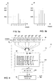
- a group of impulse response tabs is calculated in the processing unit 11, but usually all these are not fed to the equalizer 9. So, the calculated impulse response tabs are subject to selection and the tabs that give the best channel impulse response are selected. The selection is implemented in the processing unit 11 so that among all calculated impulse response tabs those are selected that include the most of energy. Further, it must be noticed that the selected tabs always form a group, that is, the correlator 11 can't select one tab here and one tab there. In this respect reference is made to figures 3a and 3b.
- Figure 3a shows how the magnitudes of nine impulse response tabs have been calculated and figure 3b shows the group of five tabs selected among those.
- the I D and Q D outputs of the correlator 8 are combined into the equalizer 9.
- the received signal a(t) is also fed to the equalizer 9.
- the purpose of the equalizer 9 is to equalize the received signal a(t) with help of the estimated channel impulse response.
- the technique in itself is widely known. It employs a matched filter and a modified Viterbi algorithm for signal processing.
- the estimated impulse response tabs are fed to the matched filter and processed.
- the output of the equalizer 9 gives an equalized signal b(t) for the decryption unit 4 (compare figure 1).
- the position signal maxpos calculated in the correlator 8 expresses the position of the maximum energy (that is, the position of the impulse response, the energy content of which is the biggest) in the received TDMA (like GSM) burst. For one received burst one position signal is received.
- the position signal maxpos is fed to the timing unit 6.
- This timing unit 6 comprises two filter units 14, 15 that are series connected with each other.
- the position signal output of the correlator 8 is connected to the input 12 of the first filter unit.
- the output 13 of the timing unit 6, which is also the output of the second filter unit, is further connected to the control unit 7.
- the first filter unit 14 comprises a first filter 16 and a separator 18 following this. By the separator 18, only desired output signals of the first filter 16 are allowed to pass to the second filter unit 15.
- the second filter unit 15 comprises a second filter 17 and a scaler 19.
- the output signal corr of the timing unit 6 is set to the suitable scaling window for the purpose of compensating the timing errors.
- the first filter 16 comprises an n state floating register 20 (figure 4), that is preferably a fifo-register (that is, a floating register where one signal sample comes in whereby another goes out).
- the position signal maxpos received from the correlator 8 is fed to the first filter 16, that is, in this case to the input 12 of the fifo register 20.
- the maxpos value of the position signal expresses the position of the maximum energy of the impulse response, and it can be calculated in connection with the calculation of the impulse response in the correlator 8, as described above.
- the calculated position signals maxpos are fed one after another to the fifo register 20 of the first filter 16, and after input of each signal the sum of the signal samples in the register 20 is calculated by the summer 21, after which the received sum "sum” is further fed to the decision unit 22, where the sum is compared with the decision parameters, and the intermediate output signal is given, based on the comparison, further to the separator 18.
- the sum "sum” of the position signals present in the register 20 at a certain moment is compared in the decision unit 22 with the decision parameters.
- the information of the nominal stage of the position signal is required. It can be in principle any signal value, so let it be nom, which is an integral number.
- the first decision parameter is formed from the sum of the nominal values of the position signals.
- the other decision parameters a n , b n are integral numbers that are suitably selected depending on the application. This is illustrated in figure 4 by the decision table 22a included in the decision unit 22, in accordance with the following table 7:
- the fifo register 20 consists of eight memory elements 20 1 , 20 2 , ..., 20 8 (Pos1, Pos2, Pos3, ..., Pos8) where eight successive position signals are saved into.
- the values of the other decision parameters a n , b n are 11, 7, 3 and the corresponding values of the intermediate signals ot: -3, -2, -1, 0, 1, 2, 3. From the decision table 22a of the decision unit 22 can be derived the intermediate signal ot, the value of which is one of said integral numbers: -3, -2, -1, 0, 1, 2, 3.
- the decision unit 22 comprises in addition to the decision table 22a also the summer 22b.
- the cumulative intermediate signal op represents the output signal of the decision unit 22.
- the cumulative intermediate signal op can be used as output signal of the first filter unit 14, but in most cases it is preferable to smoothen the output signal by feeding it first to the separator 18.
- the correction signal corr is received every other time, when the maxpos signal is entered.
- the correction of the timing is attenuated and smoothened so that it does not happen too fast and suddenly with respect of the units following it, especially those of the control unit 7 and the MLSE receiver 5.
- the second filter unit 15 includes an m state floating register 23.
- This floating register is preferably a fifo-register and its structure corresponds to the fifo register 20 of the first filter.
- the output signal op; D of the first filter unit 14 is fed into the input of the register 23.
- the successive op; D values of the output signals are saved to the memory elements 23 1 , 23 2 , 23 3 , ...23 m (Pos1, Pos2, Pos3, ..., Posm) of the floating register 23.
- the content of the register 23 is averaged, that is, the mean value is calculated from the op; D values of the included output signals of the first filter unit: the sum of the signals suml is calculated with the summer 24 and the result is divided by the number m of the elements 23 1 , 23 2 , 23 3 , ...23 m of the register 24 in the averaging unit 25.
- the signal ave 1 is the output signal of the second filter unit 15.
- a scaler 19 to the second filter unit 15, where the intermediate signal ave 1 of the second filter unit is fed to. So it is just the output signal corr of the scaler 19 that forms the output signal of the second filter unit 15 and at the same time the output signal of the timing unit 6, that is the timing correction signal. In this way the timing error correction is made more slowly in order to prevent the system from falling into an unstable state.
- the correction signal corr is received from the timing unit 6 every other time, when the position signal maxpos is entered and the range of this correction signal corr is limited to the half of the range of the intermediate signal ave 1.
- the output signal of the timing unit 6, that is, the correction signal corr is fed into the control unit 7 of the mobile station.
- the correction signal corr includes in principal information, whether the timing is OK, and if not, how big the error is and in which direction.
- the fast normal clock of the sleep clock system can be replaced between two pages by the sleep clock and the right timing of the mobile station is still maintained. It must be noticed, that the sleep clock can operate also at another time than between two pages (e.g. when the mobile station is used for communication).
- the correction signal corr of the timing unit 6 is processed in the control unit e.g. in the following way.
- the control unit 7 comprises a derivation unit 26 (figure 2), where the correction signal corr is fed to.
- the correction signal corr is derived, whereby it is possible to find out, when the timing of the clock system must be changed and to which direction.
- the output signal of the deriving unit 26, in turn, is fed to the clock unit like e.g. sleep clock system 27 in order to correct the timing so that the starting point of the page is synchronized with the clock signal.
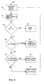
- the internal timing of the mobile station is corrected in the embodiment described above in the following way (compare flow diagram of figure 6).
- the position signal maxpos values are calculated in the correlator 8, as described above (phase 30). In the embodiment described above, these are integral numbers the range of which depends on the width of the correlating window of the correlator 8.
- the position signal maxpos values can range e.g. between -4, -3, ..., 3, 4 or 0, 1, 2, 3, 4. From these position signal values the correction signal corr is calculated in the timing unit 6 (phase 31).
- the correction signal calculated from the position signals maxpos with help of the timing unit 6 is corr0. This is noticed at the testing phase of the correction signal (phase 32).
- the correction signal corr of the timing unit 6 indicates that the frequency of the mobile station clock has changed and the timing of the clock system must be corrected.
- the output signal corr received from the timing unit 6 is one indicator relating to the timing error correction in the control unit 17; additionally, also other information relating to the timing error correction can be used for controlling and synchronizing the timing.
Landscapes
- Engineering & Computer Science (AREA)
- Computer Networks & Wireless Communication (AREA)
- Signal Processing (AREA)
- Synchronisation In Digital Transmission Systems (AREA)
- Mobile Radio Communication Systems (AREA)
Applications Claiming Priority (2)
| Application Number | Priority Date | Filing Date | Title |
|---|---|---|---|
| FI955045 | 1995-10-23 | ||
| FI955045A FI111582B (fi) | 1995-10-23 | 1995-10-23 | Menetelmä ja piirijärjestely matkaviestimen sisäisten ajatusvirheiden kompensoimiseksi |
Publications (3)
| Publication Number | Publication Date |
|---|---|
| EP0771128A2 true EP0771128A2 (fr) | 1997-05-02 |
| EP0771128A3 EP0771128A3 (fr) | 2003-07-09 |
| EP0771128B1 EP0771128B1 (fr) | 2005-08-03 |
Family
ID=8544244
Family Applications (1)
| Application Number | Title | Priority Date | Filing Date |
|---|---|---|---|
| EP96660064A Expired - Lifetime EP0771128B1 (fr) | 1995-10-23 | 1996-10-01 | Procédé et circuit de compensation des erreurs de temporisation interne dans une station mobile |
Country Status (5)
| Country | Link |
|---|---|
| US (1) | US5917868A (fr) |
| EP (1) | EP0771128B1 (fr) |
| JP (1) | JP3923571B2 (fr) |
| DE (1) | DE69635011T2 (fr) |
| FI (1) | FI111582B (fr) |
Cited By (1)
| Publication number | Priority date | Publication date | Assignee | Title |
|---|---|---|---|---|
| EP1392009A4 (fr) * | 2001-05-25 | 2009-08-26 | Mitsubishi Electric Corp | Dispositif et procede de commande de synchronisation |
Families Citing this family (6)
| Publication number | Priority date | Publication date | Assignee | Title |
|---|---|---|---|---|
| JP3907704B2 (ja) * | 1996-10-24 | 2007-04-18 | コーニンクレッカ フィリップス エレクトロニクス エヌ ヴィ | ディジタルワイヤレス通信システム及びワイヤレス無線局 |
| DE69708925T2 (de) * | 1997-02-04 | 2002-06-20 | Nokia Networks Oy, Espoo | Kompensation der dopplerverschiebung in einem mobilkommunikationssystem |
| GB2323187B (en) * | 1997-03-14 | 2001-09-19 | Nokia Mobile Phones Ltd | Data processing circuit using both edges of a clock signal |
| US6370160B1 (en) * | 1998-12-29 | 2002-04-09 | Thomson Licensing S. A. | Base to handset epoch synchronization in multi-line wireless telephone |
| US7653828B2 (en) * | 2004-05-28 | 2010-01-26 | Sap Ag | Timeout manager |
| JP5838350B2 (ja) * | 2011-02-09 | 2016-01-06 | パナソニックIpマネジメント株式会社 | 無線機及び無線通信システム |
Family Cites Families (6)
| Publication number | Priority date | Publication date | Assignee | Title |
|---|---|---|---|---|
| US5263026A (en) * | 1991-06-27 | 1993-11-16 | Hughes Aircraft Company | Maximum likelihood sequence estimation based equalization within a mobile digital cellular receiver |
| SE469678B (sv) * | 1992-01-13 | 1993-08-16 | Ericsson Telefon Ab L M | Saett foer synkronisering och kanalestimering i tdma- radiosystem |
| US5317595A (en) * | 1992-06-30 | 1994-05-31 | Nokia Mobile Phones Ltd. | Rapidly adaptable channel equalizer |
| US5428820A (en) * | 1993-10-01 | 1995-06-27 | Motorola | Adaptive radio receiver controller method and apparatus |
| FI96257C (fi) * | 1994-04-13 | 1996-05-27 | Nokia Telecommunications Oy | Menetelmä radiotaajuisen signaalin vaihevirheen määrittämiseksi, sekä vastaanotin |
| US5706314A (en) * | 1995-01-04 | 1998-01-06 | Hughes Electronics | Joint maximum likelihood channel and timing error estimation |
-
1995
- 1995-10-23 FI FI955045A patent/FI111582B/fi not_active IP Right Cessation
-
1996
- 1996-09-23 US US08/717,570 patent/US5917868A/en not_active Expired - Lifetime
- 1996-10-01 DE DE69635011T patent/DE69635011T2/de not_active Expired - Lifetime
- 1996-10-01 EP EP96660064A patent/EP0771128B1/fr not_active Expired - Lifetime
- 1996-10-17 JP JP27496296A patent/JP3923571B2/ja not_active Expired - Fee Related
Cited By (1)
| Publication number | Priority date | Publication date | Assignee | Title |
|---|---|---|---|---|
| EP1392009A4 (fr) * | 2001-05-25 | 2009-08-26 | Mitsubishi Electric Corp | Dispositif et procede de commande de synchronisation |
Also Published As
| Publication number | Publication date |
|---|---|
| EP0771128B1 (fr) | 2005-08-03 |
| US5917868A (en) | 1999-06-29 |
| EP0771128A3 (fr) | 2003-07-09 |
| FI111582B (fi) | 2003-08-15 |
| DE69635011D1 (de) | 2005-09-08 |
| JP3923571B2 (ja) | 2007-06-06 |
| FI955045L (fi) | 1997-04-24 |
| DE69635011T2 (de) | 2006-02-09 |
| FI955045A0 (fi) | 1995-10-23 |
| JPH09139710A (ja) | 1997-05-27 |
Similar Documents
| Publication | Publication Date | Title |
|---|---|---|
| EP2051558B1 (fr) | Sélection du mode de canal d'appel | |
| US6606490B1 (en) | Battery operated radio receivers having power save by reducing active reception time | |
| EP0715440A1 (fr) | Detecteur synchrone et procede de synchronisation pour un recepteur numerique de telecommunications | |
| US5621737A (en) | Communication system with link margin control and method | |
| KR20120030342A (ko) | 마이크로 전력 모드에서 gps 디바이스를 작동시키는 시스템 및 방법 | |
| CN101305572A (zh) | 无线通信系统中信令的快速检测 | |
| US6493360B1 (en) | Reception synchronization circuit, receiver using the same, and digital communication system | |
| EP0771128A2 (fr) | Procédé et circuit de compensation des erreurs de temporisation interne dans une station mobile | |
| US20030103588A1 (en) | Frequency error estimating receiver, and frequency error estimating method | |
| JP2000261357A (ja) | チャネル推定方法 | |
| JP4814698B2 (ja) | スペクトラム拡散受信機およびその方法 | |
| US6614860B1 (en) | Compensation of doppler shift in a mobile communication system | |
| CN102347918B (zh) | 精细频偏估计方法及装置 | |
| EP1364503B1 (fr) | Estimation de decalage de frequence | |
| CN101316135B (zh) | 一种td-scdma包络检波同步方法、系统及终端 | |
| SE504792C2 (sv) | Frekvens- och tidsluckesynkronisering med användning av adaptiv filtrering | |
| EP1261144A1 (fr) | Méthode et système pour l'optimisation de la longueur d'une fenêtre de recherche | |
| JP2006191583A (ja) | 受信機のパイロット・シンボル誤り率におけるバイアスの除去 | |
| JP5283182B2 (ja) | シンボル同期装置及びシンボル同期方法 | |
| JPH05508989A (ja) | 適応フィルタによる自動周波数制御 | |
| JPH09284249A (ja) | 受信同期位置制御方式 | |
| WO2002098009A1 (fr) | Procede et systeme permettant d'optimiser la longueur d'une fenetre de recherche | |
| JP3553915B2 (ja) | 無線基地局装置、dcオフセットトレーニング方法およびdcオフセットトレーニングプログラム | |
| JP4273880B2 (ja) | チャネル推定装置及びチャネル推定方法 | |
| WO2004002092A1 (fr) | Procede permettant d'estimer l'auto-correlation du bruit |
Legal Events
| Date | Code | Title | Description |
|---|---|---|---|
| PUAI | Public reference made under article 153(3) epc to a published international application that has entered the european phase |
Free format text: ORIGINAL CODE: 0009012 |
|
| AK | Designated contracting states |
Kind code of ref document: A2 Designated state(s): DE FR GB SE |
|
| RAP1 | Party data changed (applicant data changed or rights of an application transferred) |
Owner name: NOKIA CORPORATION |
|
| PUAL | Search report despatched |
Free format text: ORIGINAL CODE: 0009013 |
|
| AK | Designated contracting states |
Designated state(s): DE FR GB SE |
|
| 17P | Request for examination filed |
Effective date: 20031125 |
|
| 17Q | First examination report despatched |
Effective date: 20040220 |
|
| GRAP | Despatch of communication of intention to grant a patent |
Free format text: ORIGINAL CODE: EPIDOSNIGR1 |
|
| GRAS | Grant fee paid |
Free format text: ORIGINAL CODE: EPIDOSNIGR3 |
|
| GRAA | (expected) grant |
Free format text: ORIGINAL CODE: 0009210 |
|
| AK | Designated contracting states |
Kind code of ref document: B1 Designated state(s): DE FR GB SE |
|
| REG | Reference to a national code |
Ref country code: GB Ref legal event code: FG4D |
|
| REF | Corresponds to: |
Ref document number: 69635011 Country of ref document: DE Date of ref document: 20050908 Kind code of ref document: P |
|
| REG | Reference to a national code |
Ref country code: SE Ref legal event code: TRGR |
|
| ET | Fr: translation filed | ||
| PLBE | No opposition filed within time limit |
Free format text: ORIGINAL CODE: 0009261 |
|
| STAA | Information on the status of an ep patent application or granted ep patent |
Free format text: STATUS: NO OPPOSITION FILED WITHIN TIME LIMIT |
|
| 26N | No opposition filed |
Effective date: 20060504 |
|
| REG | Reference to a national code |
Ref country code: FR Ref legal event code: TP |
|
| REG | Reference to a national code |
Ref country code: FR Ref legal event code: CD Owner name: 2011 INTELLECTUAL PROPERTY ASSET TRUST, US Effective date: 20111123 |
|
| REG | Reference to a national code |
Ref country code: DE Ref legal event code: R082 Ref document number: 69635011 Country of ref document: DE Representative=s name: COHAUSZ & FLORACK PATENT- UND RECHTSANWAELTE P, DE |
|
| REG | Reference to a national code |
Ref country code: DE Ref legal event code: R082 Ref document number: 69635011 Country of ref document: DE Representative=s name: TBK, DE Effective date: 20120215 Ref country code: DE Ref legal event code: R081 Ref document number: 69635011 Country of ref document: DE Owner name: CORE WIRELESS LICENSING S.A.R.L., LU Free format text: FORMER OWNER: NOKIA CORP., 02610 ESPOO, FI Effective date: 20120215 Ref country code: DE Ref legal event code: R081 Ref document number: 69635011 Country of ref document: DE Owner name: CORE WIRELESS LICENSING S.A.R.L., LU Free format text: FORMER OWNER: NOKIA CORP., ESPOO, FI Effective date: 20120215 |
|
| REG | Reference to a national code |
Ref country code: GB Ref legal event code: 732E Free format text: REGISTERED BETWEEN 20120322 AND 20120328 |
|
| REG | Reference to a national code |
Ref country code: FR Ref legal event code: TP Owner name: CORE WIRELESS LICENSING S.A.R.L., LU Effective date: 20120316 |
|
| REG | Reference to a national code |
Ref country code: DE Ref legal event code: R082 Ref document number: 69635011 Country of ref document: DE Representative=s name: TBK, DE |
|
| REG | Reference to a national code |
Ref country code: DE Ref legal event code: R082 Ref document number: 69635011 Country of ref document: DE Representative=s name: TBK, DE Effective date: 20120511 Ref country code: DE Ref legal event code: R081 Ref document number: 69635011 Country of ref document: DE Owner name: CORE WIRELESS LICENSING S.A.R.L., LU Free format text: FORMER OWNER: 2011 INTELLECTUAL PROPERTY ASSET TRUST, WILMINGTON, DEL., US Effective date: 20120511 |
|
| REG | Reference to a national code |
Ref country code: GB Ref legal event code: 732E Free format text: REGISTERED BETWEEN 20120614 AND 20120620 |
|
| PGFP | Annual fee paid to national office [announced via postgrant information from national office to epo] |
Ref country code: GB Payment date: 20141001 Year of fee payment: 19 Ref country code: DE Payment date: 20140923 Year of fee payment: 19 Ref country code: FR Payment date: 20141008 Year of fee payment: 19 Ref country code: SE Payment date: 20141013 Year of fee payment: 19 |
|
| REG | Reference to a national code |
Ref country code: DE Ref legal event code: R119 Ref document number: 69635011 Country of ref document: DE |
|
| REG | Reference to a national code |
Ref country code: SE Ref legal event code: EUG |
|
| GBPC | Gb: european patent ceased through non-payment of renewal fee |
Effective date: 20151001 |
|
| PG25 | Lapsed in a contracting state [announced via postgrant information from national office to epo] |
Ref country code: DE Free format text: LAPSE BECAUSE OF NON-PAYMENT OF DUE FEES Effective date: 20160503 Ref country code: GB Free format text: LAPSE BECAUSE OF NON-PAYMENT OF DUE FEES Effective date: 20151001 |
|
| REG | Reference to a national code |
Ref country code: FR Ref legal event code: ST Effective date: 20160630 |
|
| PG25 | Lapsed in a contracting state [announced via postgrant information from national office to epo] |
Ref country code: SE Free format text: LAPSE BECAUSE OF NON-PAYMENT OF DUE FEES Effective date: 20151002 Ref country code: FR Free format text: LAPSE BECAUSE OF NON-PAYMENT OF DUE FEES Effective date: 20151102 |