EP0771418B1 - Gerät und methode zur messung der reaktionsfähigen komponenten in gasen - Google Patents
Gerät und methode zur messung der reaktionsfähigen komponenten in gasen Download PDFInfo
- Publication number
- EP0771418B1 EP0771418B1 EP95925922A EP95925922A EP0771418B1 EP 0771418 B1 EP0771418 B1 EP 0771418B1 EP 95925922 A EP95925922 A EP 95925922A EP 95925922 A EP95925922 A EP 95925922A EP 0771418 B1 EP0771418 B1 EP 0771418B1
- Authority
- EP
- European Patent Office
- Prior art keywords
- gas
- catalyst
- mixture
- reactive component
- gases
- Prior art date
- Legal status (The legal status is an assumption and is not a legal conclusion. Google has not performed a legal analysis and makes no representation as to the accuracy of the status listed.)
- Expired - Lifetime
Links
Images



Classifications
-
- G—PHYSICS
- G01—MEASURING; TESTING
- G01N—INVESTIGATING OR ANALYSING MATERIALS BY DETERMINING THEIR CHEMICAL OR PHYSICAL PROPERTIES
- G01N27/00—Investigating or analysing materials by the use of electric, electrochemical, or magnetic means
- G01N27/02—Investigating or analysing materials by the use of electric, electrochemical, or magnetic means by investigating impedance
- G01N27/04—Investigating or analysing materials by the use of electric, electrochemical, or magnetic means by investigating impedance by investigating resistance
- G01N27/14—Investigating or analysing materials by the use of electric, electrochemical, or magnetic means by investigating impedance by investigating resistance of an electrically-heated body in dependence upon change of temperature
- G01N27/16—Investigating or analysing materials by the use of electric, electrochemical, or magnetic means by investigating impedance by investigating resistance of an electrically-heated body in dependence upon change of temperature caused by burning or catalytic oxidation of surrounding material to be tested, e.g. of gas
-
- G—PHYSICS
- G01—MEASURING; TESTING
- G01N—INVESTIGATING OR ANALYSING MATERIALS BY DETERMINING THEIR CHEMICAL OR PHYSICAL PROPERTIES
- G01N25/00—Investigating or analyzing materials by the use of thermal means
- G01N25/20—Investigating or analyzing materials by the use of thermal means by investigating the development of heat, i.e. calorimetry, e.g. by measuring specific heat, by measuring thermal conductivity
- G01N25/22—Investigating or analyzing materials by the use of thermal means by investigating the development of heat, i.e. calorimetry, e.g. by measuring specific heat, by measuring thermal conductivity on combustion or catalytic oxidation, e.g. of components of gas mixtures
-
- Y—GENERAL TAGGING OF NEW TECHNOLOGICAL DEVELOPMENTS; GENERAL TAGGING OF CROSS-SECTIONAL TECHNOLOGIES SPANNING OVER SEVERAL SECTIONS OF THE IPC; TECHNICAL SUBJECTS COVERED BY FORMER USPC CROSS-REFERENCE ART COLLECTIONS [XRACs] AND DIGESTS
- Y02—TECHNOLOGIES OR APPLICATIONS FOR MITIGATION OR ADAPTATION AGAINST CLIMATE CHANGE
- Y02E—REDUCTION OF GREENHOUSE GAS [GHG] EMISSIONS, RELATED TO ENERGY GENERATION, TRANSMISSION OR DISTRIBUTION
- Y02E30/00—Energy generation of nuclear origin
- Y02E30/10—Nuclear fusion reactors
Definitions
- the invention relates to a device and method for detecting and for measuring the amount of a reactive gaseous component in a gas or in a mixture of two or more reactive gases.
- the device is useful particularly, but not exclusively, for the detection of potentially explosive gas mixtures. In some applications the action of the device may render "safe" a gas mixture which would otherwise be an explosive hazard.
- the present inventors have addressed the problem of detection and measurement of reactive components in relation to the processing of waste gases from a thermonuclear fusion reactor.
- Thermonuclear fusion produces waste gas mixtures which include the hydrogen isotopes deuterium and tritium. Whilst in the actual reactor these gases are at very low pressures e.g. 10 -5 to 10 -1 mbar, but are raised to higher pressures e.g. approximately lbar, in auxiliary gas purification and isotope separation systems. Such pressure changes expose the process to the risk of formation of explosive hydrogen/air mixtures by in-leakage of air in the low pressure section of the process loop and then subsequent compression to atmospheric pressure. Further, in this situation explosive destruction of the process loop is doubly hazardous because the gas mixture contains radioactive isotopes.
- the present inventors have now developed a sensing and measuring device and method which is able to detect and measure small amounts of oxygen in hydrogen, deuterium and tritium or a mixture thereof when the gas is at very low pressure i.e. less than 10mbar.
- the device of the invention it can be predicted whether the gas mixture is potentially explosive before it is compressed for purification and separation.
- the device and method of the invention rely for the measurement of the amount of the reactive component on the heat of reaction released or absorbed when said component reacts, under controlled conditions using a suitable catalyst, with another component in the mixture.
- a device for measuring the amount of any reactive gaseous component in a single gas or in a mixture of two or more gases, at least one of which reacts with said reactive component comprising a reaction chamber for receipt of said gas or mixture of gases, means for supportinq a catalyst suitable for catalysing the reaction between said reactive component and said gas or gases at two locations within the reaction chamber and heat sensing means at each of said locations characterised in that at one of said locations the support includes a means which limits the gas exchange rate between the catalyst at that location and the gas whose reactive component is to be measured to 0.1 to 5% of the exchange rate at the other said location.
- the receptacle which form the catalyst and thermopile supports may be at the bottom of the reaction chamber, for example formed from a suitable seal for the chamber such as a vacuum flange.
- the thermopiles may be disposed in a depression in the flange and the removable catalysts, which conveniently may be in granular or pellet form rest immediately thereabove. Wire mesh may cover the catalysts to prevent loss from the support.
- the catalysts are not chemically adhered to the thermopile heat sensors.
- the reaction chamber preferably includes a separate inlet and outlet for the gas or mixture of gases to be tested. This allows the device to be used for batch testing of a gas mixture or for continuous monitoring of a gas stream. In either case it is preferable if the chamber includes a pressure gauge in order that the chamber may be filled with gas to a pre-determined pressure or blown through the chamber at a constant pressure.
- the reaction chamber may be made of a variety of materials depending on the gases to be tested. Metal or ceramic materials are suitable as well as some plastics although these may need to be heat-resistant and/or radiation-resistant depending on the particular application.
- the above device is suitable for the detection and measurement of small amounts of oxygen i.e. 5%v/v or less, in a hydrogen, deuterium or tritium stream over a range of pressures from (10 mbar to above atmospheric. It is also suitable for detection of small amounts of hydrogen in an oxygen stream.
- the device is sensitive enough to detect amounts of oxygen or hydrogen well below the explosive threshold. It can also be used for the detection of methane in air.
- suitable catalysts to be included in the device are platinum or palladium "deoxo" catalyst, preferably supported on an alumina carrier.
- the operating temperature needs to be about 350°C or higher whereas detection of oxygen in air can be carried out at room temperatures.
- the standard catalyst mentioned above can deactivate when used at room temperature due to the catalyst surface becoming coated with the reaction product H 2 O. Therefore it is preferable to use a catalyst which has been "wet-proofed" by a proprietary process and can therefore operate at room temperature.
- a catalyst can be obtained from AECL Canada.
- the above described embodiment of the invention has sufficient sensitivity that it is able to generate a signal of greater than 5mV for 4% air in hydrogen at 10mbar pressure.
- the entire device is surrounded by an insulating housing. This then renders it suitable for use in systems where the majority gas constituent e.g. air, is not subjected to pressure changes which cause "undesirable" signals due to adsorption/desorption of gas on the catalyst surface.
- the majority gas constituent e.g. air
- the catalyst and heat sensors may be supported on a vertically disposed block of good thermal conductivity, such as, for example, aluminium or copper.
- the vertical block may support the heat sensors in receptacles, i.e. depressions or hollows in each side of the block.
- the catalyst may be placed immediately adjacent the heat sensors within the receptacles, with means provided, for example, wire mesh, to retain the catalyst in place.
- the vertical block is arranged to protrude into a reaction chamber to dispose the catalyst and heat sensors therein.
- the invention comprises a method for measuring the amount of any reactive gaseous component in a single gas or in a mixture of two or more gases, at least one of which reacts with said reactive component which comprises the steps of:-
- a differential device as described above is used and the gas or mixture of gases to be tested is brought into full contact with catalyst at one location but substantially blocked from contact with the catalyst at a second location except for a small proportion of the catalyst area.
- the signals from the heat sensors adjacent the catalysts at the two locations are arranged to cancel each other out so that the only variable between the two catalysts is the degree of exposure to any chemical reaction. Measurement of the signal therefore provides an indication of the amount of reactive component.
- the invention provides a method for measuring the amount of a reactive gaseous component in a single gas or a mixture of two or more gases, at least one of which reacts with said reactive component which comprises the steps of:
- the devices described above include a reaction chamber in which the catalysed reaction can take place, the heat sensor or sensors and catalysts are all that are essential for performing the invention.
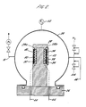
- a decive according to the invention is shown in Figure 2 and comprises a similar spherical reaction chamber 24 sealed at the base with a vacuum flange 26.
- An aluminium block 28 in the form of a column is disposed within the chamber 24 and is provided with two recesses 29a and 29b which provide support for a main thermopile 30, a main catalyst 32, a reference thermopile 34 and a reference catalyst 36.
- the catalysts 32 and 36 are retained in position by wire mesh 40.
- the reference catalyst and sensor 34,36 are covered by a gas impermeable material e.g metal foil 38 with a small hole 42. The hole admits direct exchange with the ambient gas mixture for only about 1% of the catalyst surface area.
- the outputs 44 from the main thermopile 30 and the reference thermopile 34 are connected to a mV-meter (not shown).
- the reaction chamber includes an inlet 46 for the gas to be tested and an outlet 50 as well as a pressure gauge for the chamber 52.
- thermopiles 48 and 50 are each disposed in recesses 52 and 54 respectively in a standard vacuum flange fitted in the base of the reaction chamber as in Figure 1.
- Catalyst 56 is placed on top of each of the thermopiles 48 and 52.
- the catalyst on top of the thermopile 48 is retained in position with wire mesh 62.
- the catalyst on top of the thermopile 50 is overlayed with a gas impermeable material e.g. metal foil 58.
- the foil is punctured with a small hole 60 which exposes about 1% of the catalyst surface to the gas in the reaction chamber.
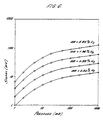
- Figure 6 shows the results of a test in which air is the majority gas in the mixture and hydrogen is included at 0.50, 0.99, 1.96 and 3.85% respectively.
- the sensitivity of the device at lbar pressure is 2.9 ⁇ V ppm hydrogen.
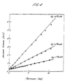
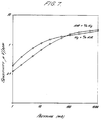
- Figure 7 shows the averaged values of Figures 3, 4 and 6 for air in hydrogen and hydrogen in air.
Landscapes
- Chemical & Material Sciences (AREA)
- Biochemistry (AREA)
- General Physics & Mathematics (AREA)
- Pathology (AREA)
- Physics & Mathematics (AREA)
- Health & Medical Sciences (AREA)
- Life Sciences & Earth Sciences (AREA)
- Analytical Chemistry (AREA)
- General Health & Medical Sciences (AREA)
- Chemical Kinetics & Catalysis (AREA)
- Immunology (AREA)
- Engineering & Computer Science (AREA)
- Combustion & Propulsion (AREA)
- Electrochemistry (AREA)
- Investigating Or Analyzing Materials Using Thermal Means (AREA)
- Investigating Or Analyzing Non-Biological Materials By The Use Of Chemical Means (AREA)
- Sampling And Sample Adjustment (AREA)
- Investigating Or Analyzing Materials By The Use Of Electric Means (AREA)
Claims (25)
- Vorrichtung zum Messen der Menge einer reaktionfähigen Gaskomponente in einem Gas oder in einer Mischung aus zwei oder mehreren Gasen, von denen mindestens eines mit der reaktionsfähigen Komponente reagiert, wobei die Vorrichtung eine Reaktionskammer (24) zur Aufnahme des Gases oder der Gasmischung aufweist, eine Einrichtung (28) zum Tragen eines Katalysators (32, 36), der zur Katalyse der Reaktion zwischen der reaktionsfähigen Komponente und dem Gas oder den Gasen geeignet ist, an zwei Stellen innerhalb der Reaktionskammer, und Wärmemesser (30, 34) an jeder dieser Stellen, dadurch gekennzeichnet, daß an einer der Stellen der Träger Mittel aufweist, die die Gasaustauschgeschwindigkeit zwischen dem Katalysator an dieser Stelle und dem Gas, dessen reaktionsfähige Komponente gemessen werden soll, auf 0,1 bis 5 % der Austauschgeschwindigkeit an der anderen Stelle beschränkt.
- Vorrichtung nach Anspruch 1, dadurch gekennzeichnet, daß das Mittel an dieser Stelle die Gasaustauschgeschwindigkeit auf 1 % der Austauschgeschwindigkeit an der anderen Stelle beschränkt.
- Vorrichtung nach Anspruch 1, dadurch gekennzeichnet, daß der Wärmemesser (34, 36) die Reaktionswärme in ein elektrisches Signal umwandelt.
- Vorrichtung nach Anspruch 1 oder 3, dadurch gekennzeichnet, daß die Signale von den zwei Wärmemessern (30, 34) elektrisch substrahiert werden können, um sich in Abwesenheit einer katalysierten Reaktion zwischen der reaktionsfähigen Komponente und einem oder mehreren Gasen gegenseitig zu löschen.
- Vorrichung nach einem der Ansprüche 1 bis 4, dadurch gekennzeichnet, daß die zwei Stellen zum Tragen des Katalysators sich auf einer Metallsäule (28) befinden, die in die Reaktionskammer (24) hineinragt.
- Vorrichtung nach Anspruch 5, dadurch gekennzeichnet, daß die Säule so ausgebildet ist, daß sie ein Gefäß (29) zur Aufnahme des Katalysators bildet.
- Vorrichtung nach Anspruch 5, dadurch gekennzeichnet, daß die Säule (28) aus Kupfer oder Aluminium besteht.
- Vorrichtung nach einem der vorherigen Ansprüche, dadurch gekennzeichnet, daß der Wärmemesser (30, 34) eine Halbleiter-Thermosäule, wie z. B. ein Pelletier-Element oder eine thermoelektrische Wärmepumpe, ist.
- Vorrichtung nach einem der vorherigen Ansprüche, dadurch gekennzeichnet, daß der Katalysator in der Katalysatorträgereinrichung (29) vorgesehen ist.
- Vorrichtung nach einem der vorherigen Ansprüche, dadurch gekennzeichnet, daß die Reaktionskammer (24) aus Metall, einem Keramikmaterial oder einem gegen Strahlung oder Wärme beständigen Kunststoff besteht.
- Vorrichtung nach einem der vorherigen Ansprüche, dadurch gekennzeichnet, daß sie eine Einrichtung zum Füllen der Kammer mit dem zu testenden Gas bis zu einem bestimmten Druck (52) aufweist.
- Vorrichtung nach einem der vorherigen Ansprüche, dadurch gekennzeichnet, daß sie ausgestaltet ist zur Bestimmung von Sauerstoff in einem Gasstrom aus Wasserstoff, Deuterium oder Tritium, oder einer Mischung von zwei oder mehreren davon.
- Vorrichtung nach einem der Ansprüche 1 bis 12, dadurch gekennzeichnet, daß sie ausgestaltet ist zur Bestimmung von Wasserstoff, Deuterium oder Tritium oder einer Mischung davon in einem Gasstrom aus Sauerstoff oder Luft.
- Vorrichtung nach Anspruch 12 oder 13, dadurch gekennzeichnet, daß sie ausgestaltet ist, um bei Gasdrucken von 1 bar oder weniger, und vorzugsweise von weniger als 10 mbar betrieben zu werden.
- Verfahren zum Messen der Menge einer reaktionsfähigen Gaskomponente in einem Gas oder einer Mischung aus zwei oder mehreren Gasen, von denen mindestens eines mit der reaktionsfähigen Komponente reagiert, dadurch gekennzeichnet, daß das Verfahren die Stufen umfaßt:a) in-Kontakt-bringen des Gases oder der Gasmischung mit einem Katalysator (32, 36), der zur Katalyse der Reaktion zwischen der reaktionsfähigen Komponente und einem oder mehreren anderen Gasen in der Mischung geeignet ist, in einer in einem der Ansprüche 1 bis 14 beanspruchten Vorrichtung,b) Bestimmen und Messen der durch die katalysierte Reaktion gebildeten oder verbrauchten Wärme, die proportional zur Menge der reaktionsfähigen Komponente ist, undc) Umwandeln der Menge der gebildeten oder verbrauchten Wärme in ein elektrisches Signal.
- Verfahren nach Anspruch 15, dadurch gekennzeichnet, daß das Gas Wasserstoff, Deuterium oder Tritium oder eine Mischung von zwei oder mehreren davon ist, und die zu bestimmende reaktionsfähige Komponente Sauerstoff ist.
- Verfahren nach Anspruch 15, dadurch gekennzeichnet, daß das Gas Sauerstoff oder Luft ist, und die zu besitmmende reaktionsfähige Komponente Wasserstoff, Deuterium oder Tritium oder eine Mischung von zwei oder mehreren davon ist.
- Verfahren nach Anspruch 15, dadurch gekennzeichnet, daß die Gasmischung Luft ist und die zu bestimmende reaktionfähige Komponente Methan ist.
- Verfahren nach einem der Ansprüche 16 bis 18, dadurch gekennzeichnet, daß der Katalysator ein Platin- oder Palladium-"Deoxo"-Katalysator ist, der sich gegebenenfalls auf einem Aluminiumoxid-Träger befindet.
- Verfahren zum Messen der Menge einer reaktionfähigen Gaskomponente in einem Gas oder einer Mischung aus zwei oder mehreren Gasen, von denen mindestens eines mit der reaktionsfähigen Komponente reagiert, dadurch gekennzeichnet, daß das Verfahren die Stufen umfaßt:a) Bereitstellen eines Katalysators (32, 36) der zur Katalyse der Reaktion zwischen der reaktionsfähigen Komponente und dem Gas oder den Gasen geeignet ist, an zwei getrennten Stellen innerhalb einer Reaktionskammer (24) zum in Kontakt bringen mit dem zu bestimmenden Gas,b) Bereitstellen eines Mittels, das die Gasaustauschgeschwindigkeit zwischen dam Katalysator an einer der Stellen (38) und dem Gas, dessen reaktionsfähige Komponente gemessen werden soll, auf 0,1 bis 5 % der Austauschgeschwindigkeit an der anderen Stelle beschränktc) Bereitstellen eines Wäremmessers (30, 34) unmittelbar neben jeder Katalysator-Stelled) elektrisches Substrahieren der Signale von den jeweiligen Wärmemessern (30, 34), um sich gegenseitig auszulöschen,e) Einführen des zu bestimmenden Gases in die Umgebung der zwei Katalysator-Stellen, undf) Bestimmen eines Signals von den Wärmemessern (30, 34), das proportional ist zur Menge der reaktionfähigen Komponente in der Mischung.
- Verfahren nach Anspruch 20, dadurch gekennzeichnet, daß das Gas Wasserstoff, Deuterium oder Tritium oder einer Mischung von zwei oder mehreren davon ist, und die zu bestimmende reaktionsfähige Komponente Sauerstoff ist.
- Verfahren nach Anspruch 20, dadurch gekennzeichnet, daß das Gas Sauerstoff oder Luft ist, und die zu bestimmende reaktionsfähige Komponente Wasserstoff, Deuterium oder Tritium oder eine Mischung aus zwei oder mehreren davon ist.
- Verfahren nach Anspruch 20, dadurch gekennzeichnet, daß die Gasmischung Luft ist und die zu bestimmende reaktionsfähige Komponente Methan ist.
- Verfahren nach einem der Ansprüche 21 bis 23, dadurch gekennzeichnet, daß der Katalysator ein Platin- oder Palladium-"Deoxo"-Katalysator ist, der sich gegebenenfalls auf einem Aluminiumoxid-Träger befindet.
- Vefahren nach einen der Ansprüche 15 bis 24, dadurch gekenneichnet, daß das zu bestimmende Gas oder die Gasmischung mit dem Katalysator bei einem Druck von weniger als 1 bar, vorzugsweise weniger als 10 mbar, in Kontakt gebracht wird.
Applications Claiming Priority (3)
| Application Number | Priority Date | Filing Date | Title |
|---|---|---|---|
| GB9414582 | 1994-07-19 | ||
| GB9414582A GB9414582D0 (en) | 1994-07-19 | 1994-07-19 | Device and method for measuring reactive components in gases |
| PCT/GB1995/001707 WO1996002826A1 (en) | 1994-07-19 | 1995-07-19 | Device and method for measuring reactive components in gases |
Publications (2)
| Publication Number | Publication Date |
|---|---|
| EP0771418A1 EP0771418A1 (de) | 1997-05-07 |
| EP0771418B1 true EP0771418B1 (de) | 1999-08-18 |
Family
ID=10758577
Family Applications (1)
| Application Number | Title | Priority Date | Filing Date |
|---|---|---|---|
| EP95925922A Expired - Lifetime EP0771418B1 (de) | 1994-07-19 | 1995-07-19 | Gerät und methode zur messung der reaktionsfähigen komponenten in gasen |
Country Status (7)
| Country | Link |
|---|---|
| EP (1) | EP0771418B1 (de) |
| JP (1) | JPH10503013A (de) |
| AT (1) | ATE183583T1 (de) |
| CA (1) | CA2195327A1 (de) |
| DE (1) | DE69511562D1 (de) |
| GB (1) | GB9414582D0 (de) |
| WO (1) | WO1996002826A1 (de) |
Families Citing this family (4)
| Publication number | Priority date | Publication date | Assignee | Title |
|---|---|---|---|---|
| JP4183281B2 (ja) * | 1996-10-22 | 2008-11-19 | ハッチ ウルトラ アナリティクス ジニーヴァ ソシエテ アノニム | 可燃性モニタおよび監視方法 |
| KR100487668B1 (ko) | 2000-06-05 | 2005-05-04 | 마쯔시다덴기산교 가부시키가이샤 | 가스농도검지기, 이것을 사용한 수소정제장치 및연료전지시스템 |
| JP4216237B2 (ja) * | 2004-09-24 | 2009-01-28 | シチズンホールディングス株式会社 | 熱電式化学センサの製造方法 |
| DE102012101621B8 (de) * | 2012-02-28 | 2013-06-13 | Rubotherm GmbH | Vorrichtung und Verfahren zur kalorimetrischen Vermessung von Sorptionsvorgängen |
Family Cites Families (6)
| Publication number | Priority date | Publication date | Assignee | Title |
|---|---|---|---|---|
| US3771960A (en) * | 1971-07-28 | 1973-11-13 | Ambac Ind | Gas analyzer |
| GB1427515A (en) * | 1972-03-07 | 1976-03-10 | Secretary Trade Ind Brit | Explosive gas detectors |
| GB1358368A (en) * | 1972-12-22 | 1974-07-03 | Vnii Analitecheskogo Pribo Ros | Apparatus for detection of combustible constituents in gas mixtures |
| US4296399A (en) * | 1977-12-21 | 1981-10-20 | A-T-O Inc. | Microminiature palladium oxide gas detector and method of making same |
| US4614721A (en) * | 1984-12-10 | 1986-09-30 | Rocwell | Heat recovery calorimeter |
| US4870025A (en) * | 1985-09-30 | 1989-09-26 | Ford Motor Company | Method of sensing methane gas-I |
-
1994
- 1994-07-19 GB GB9414582A patent/GB9414582D0/en active Pending
-
1995
- 1995-07-19 JP JP8504835A patent/JPH10503013A/ja active Pending
- 1995-07-19 AT AT95925922T patent/ATE183583T1/de active
- 1995-07-19 EP EP95925922A patent/EP0771418B1/de not_active Expired - Lifetime
- 1995-07-19 WO PCT/GB1995/001707 patent/WO1996002826A1/en not_active Ceased
- 1995-07-19 DE DE69511562T patent/DE69511562D1/de not_active Expired - Lifetime
- 1995-07-19 CA CA002195327A patent/CA2195327A1/en not_active Abandoned
Also Published As
| Publication number | Publication date |
|---|---|
| DE69511562D1 (de) | 1999-09-23 |
| GB9414582D0 (en) | 1994-09-07 |
| JPH10503013A (ja) | 1998-03-17 |
| CA2195327A1 (en) | 1996-02-01 |
| WO1996002826A1 (en) | 1996-02-01 |
| EP0771418A1 (de) | 1997-05-07 |
| ATE183583T1 (de) | 1999-09-15 |
Similar Documents
| Publication | Publication Date | Title |
|---|---|---|
| US3943751A (en) | Method and apparatus for continuously measuring hydrogen concentration in argon gas | |
| EP0763200B1 (de) | Vorrichtung zur feststellung von gasen | |
| KR100585570B1 (ko) | 유전성 유체 내의 가스 검출 방법 및 장치 | |
| US8537020B2 (en) | Visual indicator of gas sensor impairment | |
| US5055266A (en) | Method for detecting toxic gases | |
| JP2011149954A (ja) | 入力ガス流中の不純物の濃度レベルを測定する装置およびその方法、入力ガス流中の酸素の濃度レベルを測定する装置およびその方法 | |
| EP1921445A1 (de) | Wasserstoffgassensor | |
| Seiler et al. | Detection of Carbon Monoxide and Hydrogen by Conversion of Mercury Oxide | |
| US7178384B2 (en) | Method and apparatus for measuring ultralow permeation | |
| US3464797A (en) | Instrument for determining ozone | |
| CA2164438A1 (en) | Gas detection, identification and elemental and quantitative analysis system | |
| US3718434A (en) | Apparatus and method for detecting gaseous contaminants | |
| EP0771418A1 (de) | Gerät und methode zur messung der reaktionsfähigen komponenten in gasen | |
| US4835395A (en) | Continuous aqueous tritium monitor | |
| US3996005A (en) | Detection and measurement of NO2 and O3 | |
| US4858461A (en) | Permeation cell gas detector | |
| US5260585A (en) | Endpoint and/or back diffusion gas impurity detector, and method of using the same | |
| US3426579A (en) | Continuous monitor for the rapid detection of hydrogen and oxygen | |
| CA1261720A (en) | Combined sensor device for detecting toxic gases | |
| US4582991A (en) | Method of measuring the density of a material | |
| GB2527867A (en) | Detection of organics in water | |
| US4838098A (en) | Contained radiological analytical chemistry module | |
| GB2103806A (en) | Improvements relating to gas detectors | |
| GB2312279A (en) | Hydrogen detecting system | |
| US3660036A (en) | Analytical method and apparatus |
Legal Events
| Date | Code | Title | Description |
|---|---|---|---|
| PUAI | Public reference made under article 153(3) epc to a published international application that has entered the european phase |
Free format text: ORIGINAL CODE: 0009012 |
|
| 17P | Request for examination filed |
Effective date: 19970122 |
|
| AK | Designated contracting states |
Kind code of ref document: A1 Designated state(s): AT BE CH DE DK ES FR GB GR IE IT LI LU MC NL PT SE |
|
| 17Q | First examination report despatched |
Effective date: 19970605 |
|
| GRAG | Despatch of communication of intention to grant |
Free format text: ORIGINAL CODE: EPIDOS AGRA |
|
| GRAG | Despatch of communication of intention to grant |
Free format text: ORIGINAL CODE: EPIDOS AGRA |
|
| GRAH | Despatch of communication of intention to grant a patent |
Free format text: ORIGINAL CODE: EPIDOS IGRA |
|
| GRAH | Despatch of communication of intention to grant a patent |
Free format text: ORIGINAL CODE: EPIDOS IGRA |
|
| GRAA | (expected) grant |
Free format text: ORIGINAL CODE: 0009210 |
|
| AK | Designated contracting states |
Kind code of ref document: B1 Designated state(s): AT BE CH DE DK ES FR GB GR IE IT LI LU MC NL PT SE |
|
| PG25 | Lapsed in a contracting state [announced via postgrant information from national office to epo] |
Ref country code: SE Free format text: THE PATENT HAS BEEN ANNULLED BY A DECISION OF A NATIONAL AUTHORITY Effective date: 19990818 Ref country code: NL Free format text: LAPSE BECAUSE OF FAILURE TO SUBMIT A TRANSLATION OF THE DESCRIPTION OR TO PAY THE FEE WITHIN THE PRESCRIBED TIME-LIMIT Effective date: 19990818 Ref country code: LI Free format text: LAPSE BECAUSE OF FAILURE TO SUBMIT A TRANSLATION OF THE DESCRIPTION OR TO PAY THE FEE WITHIN THE PRESCRIBED TIME-LIMIT Effective date: 19990818 Ref country code: IT Free format text: LAPSE BECAUSE OF FAILURE TO SUBMIT A TRANSLATION OF THE DESCRIPTION OR TO PAY THE FEE WITHIN THE PRESCRIBED TIME-LIMIT;WARNING: LAPSES OF ITALIAN PATENTS WITH EFFECTIVE DATE BEFORE 2007 MAY HAVE OCCURRED AT ANY TIME BEFORE 2007. THE CORRECT EFFECTIVE DATE MAY BE DIFFERENT FROM THE ONE RECORDED. Effective date: 19990818 Ref country code: GR Free format text: LAPSE BECAUSE OF NON-PAYMENT OF DUE FEES Effective date: 19990818 Ref country code: FR Free format text: LAPSE BECAUSE OF FAILURE TO SUBMIT A TRANSLATION OF THE DESCRIPTION OR TO PAY THE FEE WITHIN THE PRESCRIBED TIME-LIMIT Effective date: 19990818 Ref country code: ES Free format text: THE PATENT HAS BEEN ANNULLED BY A DECISION OF A NATIONAL AUTHORITY Effective date: 19990818 Ref country code: CH Free format text: LAPSE BECAUSE OF FAILURE TO SUBMIT A TRANSLATION OF THE DESCRIPTION OR TO PAY THE FEE WITHIN THE PRESCRIBED TIME-LIMIT Effective date: 19990818 Ref country code: BE Free format text: LAPSE BECAUSE OF FAILURE TO SUBMIT A TRANSLATION OF THE DESCRIPTION OR TO PAY THE FEE WITHIN THE PRESCRIBED TIME-LIMIT Effective date: 19990818 Ref country code: AT Free format text: LAPSE BECAUSE OF FAILURE TO SUBMIT A TRANSLATION OF THE DESCRIPTION OR TO PAY THE FEE WITHIN THE PRESCRIBED TIME-LIMIT Effective date: 19990818 |
|
| REF | Corresponds to: |
Ref document number: 183583 Country of ref document: AT Date of ref document: 19990915 Kind code of ref document: T |
|
| REG | Reference to a national code |
Ref country code: CH Ref legal event code: EP |
|
| REF | Corresponds to: |
Ref document number: 69511562 Country of ref document: DE Date of ref document: 19990923 |
|
| REG | Reference to a national code |
Ref country code: IE Ref legal event code: FG4D |
|
| PG25 | Lapsed in a contracting state [announced via postgrant information from national office to epo] |
Ref country code: PT Free format text: LAPSE BECAUSE OF FAILURE TO SUBMIT A TRANSLATION OF THE DESCRIPTION OR TO PAY THE FEE WITHIN THE PRESCRIBED TIME-LIMIT Effective date: 19991118 Ref country code: DK Free format text: LAPSE BECAUSE OF FAILURE TO SUBMIT A TRANSLATION OF THE DESCRIPTION OR TO PAY THE FEE WITHIN THE PRESCRIBED TIME-LIMIT Effective date: 19991118 |
|
| PG25 | Lapsed in a contracting state [announced via postgrant information from national office to epo] |
Ref country code: DE Free format text: LAPSE BECAUSE OF FAILURE TO SUBMIT A TRANSLATION OF THE DESCRIPTION OR TO PAY THE FEE WITHIN THE PRESCRIBED TIME-LIMIT Effective date: 19991119 |
|
| EN | Fr: translation not filed | ||
| NLV1 | Nl: lapsed or annulled due to failure to fulfill the requirements of art. 29p and 29m of the patents act | ||
| REG | Reference to a national code |
Ref country code: CH Ref legal event code: PL |
|
| PLBE | No opposition filed within time limit |
Free format text: ORIGINAL CODE: 0009261 |
|
| STAA | Information on the status of an ep patent application or granted ep patent |
Free format text: STATUS: NO OPPOSITION FILED WITHIN TIME LIMIT |
|
| PG25 | Lapsed in a contracting state [announced via postgrant information from national office to epo] |
Ref country code: LU Free format text: LAPSE BECAUSE OF NON-PAYMENT OF DUE FEES Effective date: 20000719 Ref country code: IE Free format text: LAPSE BECAUSE OF NON-PAYMENT OF DUE FEES Effective date: 20000719 Ref country code: GB Free format text: LAPSE BECAUSE OF NON-PAYMENT OF DUE FEES Effective date: 20000719 |
|
| PG25 | Lapsed in a contracting state [announced via postgrant information from national office to epo] |
Ref country code: MC Free format text: THE PATENT HAS BEEN ANNULLED BY A DECISION OF A NATIONAL AUTHORITY Effective date: 20000731 |
|
| 26N | No opposition filed | ||
| GBPC | Gb: european patent ceased through non-payment of renewal fee |
Effective date: 20000719 |
|
| REG | Reference to a national code |
Ref country code: IE Ref legal event code: MM4A |