EP0771485B1 - Dispositif de fermeture d'enveloppes telles que des gaines de cables - Google Patents
Dispositif de fermeture d'enveloppes telles que des gaines de cables Download PDFInfo
- Publication number
- EP0771485B1 EP0771485B1 EP95924283A EP95924283A EP0771485B1 EP 0771485 B1 EP0771485 B1 EP 0771485B1 EP 95924283 A EP95924283 A EP 95924283A EP 95924283 A EP95924283 A EP 95924283A EP 0771485 B1 EP0771485 B1 EP 0771485B1
- Authority
- EP
- European Patent Office
- Prior art keywords
- accordance
- tool
- elements
- cable
- closure
- Prior art date
- Legal status (The legal status is an assumption and is not a legal conclusion. Google has not performed a legal analysis and makes no representation as to the accuracy of the status listed.)
- Expired - Lifetime
Links
Images




Classifications
-
- A—HUMAN NECESSITIES
- A44—HABERDASHERY; JEWELLERY
- A44B—BUTTONS, PINS, BUCKLES, SLIDE FASTENERS, OR THE LIKE
- A44B19/00—Slide fasteners
- A44B19/24—Details
- A44B19/26—Sliders
- A44B19/28—Sliders constructed to be removable from at least one stringer ; Sliders with movable parts to permit releasing of the slider in the event of jamming or obstruction
- A44B19/285—Tools for opening or closing slide fasteners
-
- B—PERFORMING OPERATIONS; TRANSPORTING
- B25—HAND TOOLS; PORTABLE POWER-DRIVEN TOOLS; MANIPULATORS
- B25B—TOOLS OR BENCH DEVICES NOT OTHERWISE PROVIDED FOR, FOR FASTENING, CONNECTING, DISENGAGING, OR HOLDING
- B25B25/00—Implements for fastening, connecting or tensioning of wire or strip
- B25B25/005—Implements for fastening, connecting or tensioning of wire or strip for applying wire clasps to hose couplings
-
- B—PERFORMING OPERATIONS; TRANSPORTING
- B25—HAND TOOLS; PORTABLE POWER-DRIVEN TOOLS; MANIPULATORS
- B25B—TOOLS OR BENCH DEVICES NOT OTHERWISE PROVIDED FOR, FOR FASTENING, CONNECTING, DISENGAGING, OR HOLDING
- B25B27/00—Hand tools, specially adapted for fitting together or separating parts or objects whether or not involving some deformation, not otherwise provided for
- B25B27/14—Hand tools, specially adapted for fitting together or separating parts or objects whether or not involving some deformation, not otherwise provided for for assembling objects other than by press fit or detaching same
- B25B27/146—Clip clamping hand tools
-
- H—ELECTRICITY
- H02—GENERATION; CONVERSION OR DISTRIBUTION OF ELECTRIC POWER
- H02G—INSTALLATION OF ELECTRIC CABLES OR LINES, OR OF COMBINED OPTICAL AND ELECTRIC CABLES OR LINES
- H02G1/00—Methods or apparatus specially adapted for installing, maintaining, repairing or dismantling electric cables or lines
-
- Y—GENERAL TAGGING OF NEW TECHNOLOGICAL DEVELOPMENTS; GENERAL TAGGING OF CROSS-SECTIONAL TECHNOLOGIES SPANNING OVER SEVERAL SECTIONS OF THE IPC; TECHNICAL SUBJECTS COVERED BY FORMER USPC CROSS-REFERENCE ART COLLECTIONS [XRACs] AND DIGESTS
- Y10—TECHNICAL SUBJECTS COVERED BY FORMER USPC
- Y10T—TECHNICAL SUBJECTS COVERED BY FORMER US CLASSIFICATION
- Y10T29/00—Metal working
- Y10T29/49—Method of mechanical manufacture
- Y10T29/49764—Method of mechanical manufacture with testing or indicating
- Y10T29/49771—Quantitative measuring or gauging
-
- Y—GENERAL TAGGING OF NEW TECHNOLOGICAL DEVELOPMENTS; GENERAL TAGGING OF CROSS-SECTIONAL TECHNOLOGIES SPANNING OVER SEVERAL SECTIONS OF THE IPC; TECHNICAL SUBJECTS COVERED BY FORMER USPC CROSS-REFERENCE ART COLLECTIONS [XRACs] AND DIGESTS
- Y10—TECHNICAL SUBJECTS COVERED BY FORMER USPC
- Y10T—TECHNICAL SUBJECTS COVERED BY FORMER US CLASSIFICATION
- Y10T29/00—Metal working
- Y10T29/49—Method of mechanical manufacture
- Y10T29/49826—Assembling or joining
- Y10T29/49833—Punching, piercing or reaming part by surface of second part
- Y10T29/49835—Punching, piercing or reaming part by surface of second part with shaping
-
- Y—GENERAL TAGGING OF NEW TECHNOLOGICAL DEVELOPMENTS; GENERAL TAGGING OF CROSS-SECTIONAL TECHNOLOGIES SPANNING OVER SEVERAL SECTIONS OF THE IPC; TECHNICAL SUBJECTS COVERED BY FORMER USPC CROSS-REFERENCE ART COLLECTIONS [XRACs] AND DIGESTS
- Y10—TECHNICAL SUBJECTS COVERED BY FORMER USPC
- Y10T—TECHNICAL SUBJECTS COVERED BY FORMER US CLASSIFICATION
- Y10T29/00—Metal working
- Y10T29/49—Method of mechanical manufacture
- Y10T29/49826—Assembling or joining
- Y10T29/49947—Assembling or joining by applying separate fastener
- Y10T29/49954—Fastener deformed after application
- Y10T29/49956—Riveting
- Y10T29/49957—At least one part nonmetallic
-
- Y—GENERAL TAGGING OF NEW TECHNOLOGICAL DEVELOPMENTS; GENERAL TAGGING OF CROSS-SECTIONAL TECHNOLOGIES SPANNING OVER SEVERAL SECTIONS OF THE IPC; TECHNICAL SUBJECTS COVERED BY FORMER USPC CROSS-REFERENCE ART COLLECTIONS [XRACs] AND DIGESTS
- Y10—TECHNICAL SUBJECTS COVERED BY FORMER USPC
- Y10T—TECHNICAL SUBJECTS COVERED BY FORMER US CLASSIFICATION
- Y10T29/00—Metal working
- Y10T29/49—Method of mechanical manufacture
- Y10T29/49826—Assembling or joining
- Y10T29/49947—Assembling or joining by applying separate fastener
- Y10T29/49959—Nonresilient fastener
-
- Y—GENERAL TAGGING OF NEW TECHNOLOGICAL DEVELOPMENTS; GENERAL TAGGING OF CROSS-SECTIONAL TECHNOLOGIES SPANNING OVER SEVERAL SECTIONS OF THE IPC; TECHNICAL SUBJECTS COVERED BY FORMER USPC CROSS-REFERENCE ART COLLECTIONS [XRACs] AND DIGESTS
- Y10—TECHNICAL SUBJECTS COVERED BY FORMER USPC
- Y10T—TECHNICAL SUBJECTS COVERED BY FORMER US CLASSIFICATION
- Y10T29/00—Metal working
- Y10T29/49—Method of mechanical manufacture
- Y10T29/49826—Assembling or joining
- Y10T29/49947—Assembling or joining by applying separate fastener
- Y10T29/49966—Assembling or joining by applying separate fastener with supplemental joining
- Y10T29/4997—At least one part nonmetallic
-
- Y—GENERAL TAGGING OF NEW TECHNOLOGICAL DEVELOPMENTS; GENERAL TAGGING OF CROSS-SECTIONAL TECHNOLOGIES SPANNING OVER SEVERAL SECTIONS OF THE IPC; TECHNICAL SUBJECTS COVERED BY FORMER USPC CROSS-REFERENCE ART COLLECTIONS [XRACs] AND DIGESTS
- Y10—TECHNICAL SUBJECTS COVERED BY FORMER USPC
- Y10T—TECHNICAL SUBJECTS COVERED BY FORMER US CLASSIFICATION
- Y10T29/00—Metal working
- Y10T29/53—Means to assemble or disassemble
- Y10T29/53039—Means to assemble or disassemble with control means energized in response to activator stimulated by condition sensor
- Y10T29/53061—Responsive to work or work-related machine element
- Y10T29/53065—Responsive to work or work-related machine element with means to fasten by deformation
- Y10T29/5307—Self-piercing work part
-
- Y—GENERAL TAGGING OF NEW TECHNOLOGICAL DEVELOPMENTS; GENERAL TAGGING OF CROSS-SECTIONAL TECHNOLOGIES SPANNING OVER SEVERAL SECTIONS OF THE IPC; TECHNICAL SUBJECTS COVERED BY FORMER USPC CROSS-REFERENCE ART COLLECTIONS [XRACs] AND DIGESTS
- Y10—TECHNICAL SUBJECTS COVERED BY FORMER USPC
- Y10T—TECHNICAL SUBJECTS COVERED BY FORMER US CLASSIFICATION
- Y10T29/00—Metal working
- Y10T29/53—Means to assemble or disassemble
- Y10T29/53709—Overedge assembling means
- Y10T29/53783—Clip applier
Definitions
- the invention relates to a device for Closing wrappings such as cable hoses, flexible Pipelines or container elements using a closure device provided on a tool, on the two opposite edge parts of the casing via a slide arranged on the tool Locking elements alternate with each other and when opening be hooked apart or separated.
- a coil spring zipper is made of plastic for closing slits in duvet covers or Pillowcases (DE PS 10 46 539) known, where the dome end point after picking up the Slider from the coupled lock by a removable, connecting both straps and insertable into these Connection clamp lockable against tearing is.
- the assembly of such a zipper for cable hoses is very time-consuming because the closure element for the zipper with the associated Slider can only be operated by hand. Therefore it takes a lot of time to use cable conduits to close such a slide. Since the in the inserted cables on the cable wall exerting a relatively large amount of pressure is beyond that a very large effort is required, so that the locking mechanism is very difficult and in some Cases does not move at all.
- the invention is based on the object the device for sealing envelopes, such as Cable hoses to train and arrange such that the locking elements easily with a single tool and can be assembled and secured very quickly can.
- the object is achieved in that one tool to hold the slide another Device for securing the assembled locking elements or connecting elements provided is independent of the position of the slide can be activated. Due to the advantageous training and arrangement of the tool, the closing elements, for example a zipper, easily in put together in a single operation and by means of the same tool can be secured so that at the closing elements acting tensile forces an opening the closing elements is not possible. This can So the working procedure for closing tear zipper connections to cable hoses are significantly cheaper.
- the closing elements for example a zipper
- the device for Secure the assembled locking elements in the area the slider is provided. Since the device for Securing the assembled locking elements relatively is provided close to the slide, is prevented the locking elements assembled by the slide open again automatically if this is the case Securing element used on the locking elements is.
- An additional option is according to a training the device according to the invention that the device to secure the assembled locking elements or a zipper with cover on the direction of movement of the slide in front or behind the slider is provided.
- the device from a guided on the tool Stamp and an anvil cooperating with this or a matrix that is formed over a Actuating element can be activated.
- the stamp and of the anvil interacting with the stamp brackets in the Insert the zipper that the assembled Closing elements of the zipper against separation to back up.
- the device via an actuator can be activated, which interacts with an encoder, that after covering a certain distance of the tool triggers an actuating pulse and an adjustment of the stamp.
- an actuator By using an im
- the area of the stamp provided can automatically an actuating pulse is triggered via the encoder.
- the device for securing the assembled Closing elements of a zipper with a hydraulic, pneumatic or electric actuator is in operative connection with the actuator and / or the stamp is in operative connection.
- the electrical actuator By means of hydraulic or pneumatic respectively also the electrical actuator the device for securing the locking elements optimal use and also via an external encoder activate when the tool is a certain distance and for example at a node has arrived, in the area of the zipper or the associated locking elements should be secured. This also makes it possible always use the backup device automatically, if a certain position on the zipper is reached.
- the closure device and / or the device for securing the assembled A measuring device is assigned to locking elements, which can be connected to a computer, and that the measuring device from a measuring wheel or a pulse generator consists of one covered by the tool Distance covered and at a certain Sends a position information to the encoder, which causes the stamp to be adjusted.
- a measuring device which is advantageous Way provided in the area of the closure device is the distance between two specific ones Points or connection points of cable hoses determine in a cost-effective manner and thereby create the ability to automatically create a backup of two interlocking locking elements reach when a certain distance traveled is or a corresponding node above the tool was activated, so that the encoder due to a corresponding impulse the closure device activated.
- the measuring device, the Locking device and the device for securing of the assembled locking elements in one unit are summarized.
- the measuring device, the closure device and the device for Secure the assembled locking elements in one electrical module are summarized, the measuring device, the locking device and the device to secure the assembled locking elements in operative connection with an electrical control device stand.
- the computer belongs to the control device, via its control program stored in the database the device for securing the assembled Locking elements depending on the distance traveled Distance of the tool is controllable and that Tool with a device for recording various Data is equipped with a cable set that in connection with a power supply device stands.
- the tool with a acoustic and / or optical display device or a display.
- the calculator can all in the Production recordable cable sets and record accordingly design the customer's wishes so that they can be used individually for certain types of motor vehicles are. This creates the opportunity the operator of the tool all important information to make available so that this just pull the tool through the zipper must to the individual locking elements to each other connect and in the area of a node two merged Secure cable hoses. So it is no longer necessary before using the work tool to carry out complex measuring work in order to achieve a desired Place the securing element.
- the tool can be used fully automatically, so that on the usual preparations can be dispensed with.
- the tool has a Has unlocking device that over the encoder is controllable and releases locking elements when in a created wiring harness another turn inserted or to the main cable junction to be connected, and that the tool with equipped with several devices for securing the clips is.
- the radius R is a size between 1 and 50 mm having. Due to the advantageous design of the individual Closing elements, either as pass elements or can be designed as tongue and groove elements, is obtained using the tool that the individual Closing elements put together, a very tearproof Cable hose, which can also withstand high pressure loads does not open further. Leave the locking elements through the tool with little effort assemble in a very short time and by using the measuring organs are only closed as much cable hose as required for a certain distance is. Even if there are such cable hoses do not always close the individual cables easily let the capping work through the used tool much easier.
- the opposite Fasteners can be brought into contact with one another Have surfaces on which the adhesive can be applied is and that the opposite fasteners treated in this way on their opposite surfaces that they form a firm connection with each other.
- the tool assembled locking elements in the area of a node before and / or after a node and / or in the area of a closing element via a fastening element or a bracket can be secured using the facility between two opposite Closing elements are used.
- 24 denotes a tool, that as a device for sealing envelopes, such as cable hoses 23, flexible pipes or container elements serves.
- the tool 24 consists of a fixed handle 1 and one articulated with the handle 1 Handle 2, which has a hinge pin 15 with the Handle 1 is pivotally connected.
- the handle 1 has a housing part 22 for receiving a display 17 to reproduce parts of the drawing or Data information, a device 29 for securing assembled Locking elements 26 one shown in Figure 5 Zipper 57 on.
- a magazine 33 for receiving the closing elements 26 is in the housing part 22 .
- the magazine 33 is a component the device for securing the assembled Locking elements 26.
- the individual locking elements respectively Brackets 26 received in the magazine 33 are by means of a clamping device 4th and a spring not shown in the drawing Magazine 33 towards the outlet opening of the device 29 pressed.
- the device 29, also called Stapler can be called is over a hinge pin 7 in the housing part 22 between a starting position and a working position against the Effect of a spring 6 pivotally added.
- the Handle 2 also has an actuator 58, the in operative connection with a triggering device 55 stands so that when actuating the actuator 58 Means 29 for securing the assembled Closing elements 26 is activated and thereby fasteners or brackets 62 by means of a Anvil or stamp 54 according to Figure 10 and a die cooperating with the die 10 in the zipper 57 are used so that the already assembled closing elements 26 against loosening can be secured.
- the fastening elements 62 can be made from a U-shape Braces are made with their two legs each on the back of the closing elements 26 in the cable tube 23 pressed in and then by means of Anvil or the die 10 according to FIG. 11 be angled.
- the radius R should at least be between 5 and 50 mm in size.
- a slide 27 provided, which consists of two opposite walls 51st is formed and from a corresponding middle part consists of the assembled locking elements 26 can be unhooked again if the slide 27 is moved downward according to FIG. If the slide 27 is moved upwards according to FIG. 5, then the opposing locking elements 26 hooked together.
- the device 29 by means of the return spring 6 after a tacker operation in the in Figure 1 shown moved back and remains in this position until the control element 58 is operated.
- the device 29 is for this pivotable about the hinge pin 7 in the housing part 22 added.
- the device 29 is also above a Hinge pin 63 with the control element 58 in operative connection.
- the closing elements 26 of the Zipper 57 are assembled according to FIG. 5, the slide 27 is moved upwards.
- the slide 27 has one Cable set one of the nodes shown in Figure 7 between 100 and 103 respectively Closing end 104 is reached, the control element 58 actuated and thereby the device 29 activated and the corresponding closing element 26 in the cable hose 23 introduced.
- the stamp 54 of the device advantageously lies 29 close to or behind the slide 27 respectively the associated spreading tongue 64 for opening of the closing elements 26.
- the spreading tongue 64 as already mentioned, the closing elements 26 again be hooked apart when the slide 27 according to Figure 5 is adjusted downwards.
- the tool 24 or the Means 29 for securing the assembled Closing elements 26 of the zipper 57 with a electrical, hydraulic or pneumatic actuator or an actuating cylinder 21 in Active connection So the device 29 should be activated the actuating cylinder 21 pressurized with compressed air so that the pneumatic Actuating cylinder with the associated trigger device activated and the stamp 54 according to Figure 10 down is moved and thereby the fasteners respectively the clips 62 are pressed into the cable hose will.
- the actuating cylinder or the stamp 54 is an electrical one optically appealing encoder 56 (FIG. 10) assigned, which after driving a certain Distance of the tool 24 triggers an actuating pulse, for example when node 101 reaches is and thereby an adjustment of the stamp 54th is effected.
- the device 29 for Securing the assembled locking elements 26 a Measuring device 13 ( Figure 1) or according to FIG. 8 is associated with an odometer 40 which the exact distance between two nodes 101 and 102 or 102 and 103 detected and after detection each of these nodes then an actuating pulse triggers via encoder 56 when a particular one Distance traveled or the encoder 56 has reached or passed node 103.
- the triggering process of a closure device 25 or The device 29 can therefore always be addressed when a certain distance is covered or, as already mentioned, the Encoder 56 a corresponding node point 102 or 103 happens.
- the tool 24 with a device for detecting various Data is equipped by a cable set 61, which by means of a power supply device 18 Energy is supplied.
- Displays 17 can also be an optical warning device or a diode is provided on the tool 24 be that responds when a certain Distance traveled or one of the Nodes 101 or 102 or 103 passes has been.
- Another improvement to tool 24 will also achieved in that different in a database Dimensions of cable hose assemblies 60 and different branches or separate strands or Distances are recorded, so that based on this data a cable set with its individual branches via the computer created for a specific vehicle type can be.
- This cable set 61 can then also on made visible on a screen or over one Printer can be printed out.
- All data relating to the cable harness can be recorded create different cable sets 61, which according to Customer request for a specific vehicle type in the form a printout of the operator and the tool 24 be made accessible.
- FIG. 7 shows the cable set 61 already mentioned, the one from a main harness 110 with numerous branched cable harnesses 105, 106, 107, 108 and 109 may exist, hereinafter referred to as cable branches be designated.
- cable branches be designated.
- the individual Cable branches 105 to 109 pre-assembled and with each covered a cable tube 23. So far, the prefabricated cable branches on one with marking elements provided assembly table and then after extensive measurement work with the main cable harness 110 connected. After this assembly preparation was hit, the main harness 110 with the Cable hose 23 are provided. This was the Tool 24 used. Because of the invention Training the tool 24, it is no longer necessary the cable harness in the manner described measured, assembled or completed.
- the assembly process or the creation of the Cable set 61 results from the two functional representations according to FIGS. 8 and 9.
- a database 30 first all functions or criteria a cable harness for the motor vehicles to be created is recorded, for example, database 30 entered which harnesses to the alternator, to the tail lights, the controls or the control hydraulics or to be connected to the airbag. Every motor vehicle can have numerous functional groups have that over the individual cable runs with the Power supply 18 and the control respectively Control devices are connected. Are such data or information about the cable set 61, so you can according to a graphic preparation 31 can be displayed as a structure diagram. After investigation of customer request 32 becomes the corresponding one Retrieved cable set and in a production planning 34 brought in.
- the Operator after covering this distance either optically or acoustically via a display device, for example via the display 17 and can now connect the first cable harness 105 with the Connect main wiring harness 110 or out of hose 23 lead out if the harness 105 has been parallel was routed to the main wiring harness 110.
- the Area of node 101 is according to the graph Representation (according to FIG. 8 at 39) by means of the tool 24 and the device 29 for securing the assembled Closing elements 26, the clip 62 in the Cable hose 23 inserted so that after this operation the closing elements 26 are no longer unhooked can be.
- a securing element before and after the node 101 or a bracket 62 is used.
- Such clips 62 are to be retrofitted can be solved by one in the drawing Not shown lifting device, the Tool 24 can be provided, removed again, without damaging the cable hose 23 becomes.
- the workflow for creating the Cable set 61 can be further improved.
- According to 8 shows all the data of a cable set, can be processed using a CAD system 46 and are provided at 47 according to FIG. 9, order the production order (server) 48 of the to set individual cable sets 61.
- the transfer of the Data 49 from the server 48 to the tool 24 can be sent via Radio, diskette or EPROM can be transmitted. To this This gives you optimal control of the tool 24 when creating a cable set 61.
- the individual Information can be provided by the operator can be read on the display 17 (see Info Closing 50 according to Figure 8). After driving a certain one The operator is driven by means of Display 17 (according to distance display 52 according to FIG.
- the cable hose shown in Figure 14 or the envelope serves to hold parts such as e.g. Cables, electrical parts or other electrical Share that from moisture or splashing water should be protected.
- the wrapping respectively the cable hose 23 'can be according to FIGS. 13 and 14 consist of two curved side walls, the one with reference to Figures 13 and 14 horizontally extending wall part are connected.
- an expansion part 122 In the lateral, opposite wall parts of the casing 23 'or in the horizontal Wall part is an expansion part 122, so that if the pressure is excessive, the cross-section when the image is taken the cable parts can be changed and thus better the outer contour of the individual cable elements adjusts.
- the expansion part 122 can be, for example, an accordion be trained. However, it is also possible the expansion part 122 is Z-shaped in a certain area train, so that this area at more pressure until a continuous one one-piece, not folded wall forms.
- the cable hose itself can also be expanded from one be made of stretchable material that the Outer contours of the parts arranged in the cable hose adjusts.
- the two opposite wall parts with their respective ends 121 at two opposite ones Closing elements 113 firmly connected The end of the wall part 121 can for example over a thermal connection or an adhesive connection firmly connected to the closing element 113 will.
- the two can be joined together Closing elements 113 from a fitting element respectively hook-shaped spring element 115, the in a corresponding, adapted to the contour of the spring element Groove 116 is inserted if this Tool 24 with corresponding sliding elements 112 against the back of the two opposing locking elements 113 is pressed.
- the rear 113 be approximately V-shaped, into which the sliding elements 112 are pushed in and then on the Drive the outer contour of the sliding elements 112 along so that during this operation, the closing elements 113 are inserted into one another become a solid connection produce with each other.
- a tab 123 is located above the assembled closing elements 113 a tab 123, at least when starting work on a closing element, according to FIG. 3 the left closing element 113, is firmly connected.
- This tab 123 overlaps the entire upper surface of the two joined closing elements 113 and covers a groove or a space 117 formed between surfaces 118 becomes.
- the assembled opposite adhesive surfaces 118 are at a distance from each other, so that in this space or in this groove 117 an adhesive 119 can be introduced.
- the adhesive 119 is according to FIG. 14 via an injection mold fed. Only the spray nozzle 120 is shown in FIG. 14 of the injection mold not shown.
- the adhesive 119 is inserted into the upper groove 117 and closes the interior of the cable hose 23 'sealingly, so that no splashing water respectively no moisture in the interior of the Cable hose 23 'can penetrate. Should the cable hose must be absolutely watertight Wall of the cable hose can be designed accordingly, so that they can withstand a corresponding pressure can.
- the tab 123 can only the tab 123 a tight and tight connection produce between the two closing elements 113.
- the tab 123 can for example with the Welding surface 124 of the right closing element 113 an adhesive be connected.
- the tab 123 via an ultrasonic welding process to be sealingly connected to the welding surface 124.
- welding tool 111 used, the an ultrasonic weld between the adhesive surfaces manufactures.
- the expansion part 122 is zigzag Course with corresponding depressions that form an angle Have ⁇ or ⁇ , which is between 45 ° and 110 ° or advantageously between 50 ° and 95 ° can be.
- FIG. 14 there are four in a row arranged depressions through the zigzag Course of the expansion part 122 shown. Depending on Cross-sectional size can also extend the expansion part and then has a correspondingly larger number from wells.
- the expansion part 122 provided in the lower wall part can also in the side parts of the wall elements of the envelope to get integrated.
- the advantageously trained hereby Envelope or the cable hose 23 ' with the easily assembled locking elements can be done in a short time using the appropriate tool Assemble the time very precisely without great effort.
- the cable hose 23, 23 if the cable hose 23, 23 'again be opened, so only the individual closure elements or the adhesive connection is removed, and then take the locking elements apart.
- the opening of the cable hose 23 can in particular make it particularly easy if there is no adhesive connection but just a pluggable respectively interconnectable connection is selected.
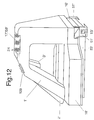
- the tool 24 be equipped with controls 129 which in Handle 2 are integrated and in connection with one not shown calculator on the tool a control function trigger so that - as described at the beginning - the cable tube 23 'is assembled.
- the individual connecting elements 26 can according to 16 by means of a 128 provided in an adhesive tank Glue are connected. It is also possible the connecting elements 26 by means of a welding transformer ( Figure 15) to connect.
Landscapes
- Engineering & Computer Science (AREA)
- Mechanical Engineering (AREA)
- Installation Of Indoor Wiring (AREA)
- Electric Cable Installation (AREA)
- Insulated Conductors (AREA)
- Details Of Indoor Wiring (AREA)
- Hand Tools For Fitting Together And Separating, Or Other Hand Tools (AREA)
- Cable Accessories (AREA)
- Load-Engaging Elements For Cranes (AREA)
Claims (34)
- Dispositif pour la fermeture d'enveloppes telles que des gaines de câble (23), des conduits de tuyaux flexibles ou d'éléments de contenants au moyen d'un dispositif de fermeture (25) monté sur un outil (24), dispositif par lequel des éléments de fermeture (26) sur deux parties en bordure de l'enveloppe qui se font face sont assemblés en alternance et défaits pour l'ouverture par un curseur (27) disposé sur l'outil (24), caractérisé en ce que sur l'outil (24) qui reçoit le curseur (27) est prévu un autre dispositif (29) pour arrêter les éléments de fermeture assemblés ou les éléments de jointure (26), dispositif activable indépendamment de la position du curseur (27).
- Dispositif selon la revendication 1, caractérisé en ce que le dispositif (29) destiné à arrêter les éléments de fermeture (26) assemblés est prévu dans la zone du curseur.
- Dispositif selon la revendication 1 ou 2, caractérisé en ce que le dispositif (29) pour arrêter les éléments de fermeture (26) assemblés, ou une fermeture à glissière, est prévu en amont ou en aval du curseur (27) en tenant compte du sens de déplacement du curseur (27).
- Dispositif selon la revendication 1, caractérisé en ce que le dispositif (29) est constitué par un poinçon (54) guidé par l'outil (24) et par une enclume ou une matrice (10) en interdépendance avec le poinçon, ledit dispositif étant activable par l'élément actionneur (58).
- Dispositif selon l'une ou plusieurs des revendications ci-avant, caractérisé en ce que le dispositif (29) pour arrêter les éléments de fermeture (26) assemblés consiste en un poinçon (54) guidé par l'outil (24) et en une enclume ou une matrice (10) en interdépendance avec le poinçon, le dispositif (29) étant activable par un élément actionneur (58) en interaction avec un capteur (56) qui, une fois que l'outil (24) a parcouru une certaine distance, déclenche une impulsion d'actionnement et un changement de position du poinçon (54).
- Dispositif selon l'une ou plusieurs des revendications ci-avant, caractérisé en ce que le dispositif (29) pour l'arrêt des éléments de fermeture (26) assemblés d'une fermeture à glissière (57) est en interdépendance avec un dispositif actionneur (21) hydraulique, pneumatique ou électrique en interaction avec l'élément actionneur (58) et/ou le poinçon (54).
- Dispositif selon l'une ou plusieurs des revendications ci-avant, caractérisé en ce que le dispositif (29) pour arrêter les éléments de fermeture (26) assemblés consiste en un cylindre actionneur (21) hydraulique ou pneumatique relié en interdépendance active avec un dispositif déclencheur (55) du poinçon (54).
- Dispositif selon la revendication 1, caractérisé en ce qu'un dispositif de mesure (13) connectable à un calculateur est assigné au dispositif de fermeture (25) et/ou au dispositif pour l'arrêt des éléments de fermeture (26) assemblés.
- Dispositif selon la revendication 1, caractérisé en ce que le dispositif de mesure (13) consiste en une roue mesureuse ou un générateur d'impulsion qui enregistre une distance parcourue par l'outil (24) et, à un endroit défini, transmet une information d'actionnement au capteur (56), qui a pour effet le changement de position du poinçon (54).
- Dispositif selon la revendication 1, caractérisé en ce que le dispositif de mesure (13), le dispositif de fermeture (25) et le dispositif pour l'arrêt des éléments de fermeture (26) assemblés sont regroupés dans une unité de construction.
- Disposiitf selon la revendication 1, caractérisé en ce que le dispositif de mesure (13), le dispositif de fermeture (25) et le dispositif pour l'arrêt des éléments de fermeture (26) assemblés sont regroupés dans un module électrique.
- Dispositif selon la revendication 1, caractérisé en ce que le dispositif de mesure (13), le dispositif de fermeture (25) et le dispositif pour l'arrêt des éléments de fermeture (26) assemblés sont regroupés dans un module électrique, le dispositif de mesure (13), le dispositif de fermeture (25) et le dispositif destiné à arrêter les éléments de fermeture (26) assemblés étant connectés à un dispositif de commande électrique (59).
- Dispositif selon la revendication 1, caractérisé en ce que le calculateur (30) fait partie du dispositif de commande (59), calculateur par le biais du programme de commande stocké en mémoire duquel le dispositif (29) destiné à l'arrêt des éléments de fermeture (26) assemblés peut être commandé en fonction d'une distance parcourue par l'outil (24).
- Dispositif selon la revendication 1, caractérisé en ce que l'outil (24) est équipé d'un dispositif pour la saisie de différentes données relatives à un jeu de câbles (61), dispositf relié à un dispositif d'alimentation en courant (18).
- Dispositif selon la revendication 1, caractérisé en ce que l'outil (24) est doté d'un dispositif d'indication sonore et/ou optique, ou d'un affichage (17).
- Dispositif selon l'une ou plusieurs des revendications ci-avant, caractérisé en ce que l'outil (24) présente un dispositif de déblocage activable par le capteur (56) et qui défait les éléments de fermeture (29) lorsque une nouvelle dérivation (106) doit être insérée dans un jeu de câble fini (61) ou doit être raccordée à la dérivation de câble principale (110).
- Dispositif selon la revendication 2, caractérisé en ce que l'outil (24) est équipé de différents dispositifs pour l'arrêt des agrafes (62).
- Dispositif selon la revendication 5, caractérisé en ce que les deux extrémités opposées de l'enclume (10) peuvent présenter une courbure.
- Dispositif selon la revendication 5, caractérisé en ce que la courbure est déterminée par le rayon = R qui est inférieur de moitié à l'épaisseur = D de l'enclume (10).
- Dispositif selon la revendication 5, caractérisé en ce que le rayon R présente une dimension comprise entre 1 et 50 mm.
- Enveloppe réalisée avec le dispositif selon la revendication 1, caractérisée en ce que l'enveloppe ou la gaine de câble (23) fabriquée avec ce dispositif, présente, en tant qu'éléments de fermeture (26) une fermeture à glissière (57) avec des dents qui s'engrènent ou des éléments emboítables en languettes et rainures (114, 115), ou bien des éléments de jointure pouvant être appliqués les uns contre les autres par collage ou par soudage.
- Enveloppe réalisée avec le dispositif selon la revendication 1, caractérisée en ce que la clavette (115) constitue un fermoir qui s'emboíte dans la rainure (114).
- Enveloppe réalisée avec le dispositif selon la revendication 1, caractérisée en ce que les éléments de jointure opposés de l'élément de fermeture (26) peuvent être reliés l'un à l'autre par une colle.
- Enveloppe réalisée avec le dispositif selon la revendication 1, caractérisée en ce que les éléments de jointure opposés de l'élément de fermeture (26) peuvent être reliés par voie thermique.
- Enveloppe réalisée avec le dispositif selon la revendication 1, caractérisée en ce que les éléments de jointure opposés présentent des surfaces pouvant être mises à plat et sur lesquelles la colle peut être appliquée.
- Enveloppe réalisée avec le dispositif selon la revendication 1, caractérisée en ce que les éléments de jointure (26) subissent sur leurs surfaces opposées un traitement tel qu'elles soient rendues fermement solidaires.
- Enveloppe réalisée avec le dispositif selon la revendication 1, caractérisée en ce que l'enveloppe (23) présente des éléments extensibles (122) pour la modification de sa section.
- Procédé pour la fermeture d'enveloppes, telles que des gaines de câbles (23), des conduits de tuyaux flexibles ou des éléments de contenants, convenant à un dispositif selon la revendication 1, caractérisé en ce que, au moyen de l'outil (24), les éléments de fermeture (26) sont d'abord assemblés et rendus fermement solidaires au moyen d'un dispositif (29) destiné à arrêter les éléments de fermeture (26) assemblés, un, deux ou plusieurs éléments de fermeture (26) pouvant être mis en place dans la gaine de câble dans la zone du point de ramification (101).
- Procédé pour la fermeture d'enveloppes, telles que des gaines de câbles (23), des conduits de tuyaux flexibles ou des éléments de contenants, convenant à un dispositif selon la revendication 1, caractérisé en ce que sont stockées dans une banque de données (30) différentes cotes relatives à des configurations de câbles (60) et à diverses ramifications (105 à 109) ou à des faisceaux séparés (110 à 103) et/ou les distances entre deux points de jonction de configurations de câbles (60), données qui sont mises à disposition du dispositif de commande (59) de l'outil (24).
- Procédé convenant pour un dispositif selon l'une des revendications 1 ou 15, caractérisé par les étapes de process suivantes:a) entrée dans la banque de données (30) du numéro de la clé d'un type de véhicule défini conformément aux desiderata du client,b) choix du jeu de câbles (61) conformément au type de véhicule et aux desiderata du client (32),c) détermination de l'ordre chronologique des véhicules à monter (34) dans un ordre défini de 1 à n,d) assemblage de la fermeture à glissière au moyen de l'outil (24),e) détermination de la distance entre deux points de ramification (100 et 101) du jeu de câbles (61),f) arrêt des éléments de fermeture (26) de la fermeture à glissière (57) au moyen du dispositif (29).
- Procédé convenant à un dispositif selon l'une des revendications 1 ou 15, caractérisé par les étapes de process suivantes:a) entrée dans la banque de données (30) du numéro de la clé d'un type de véhicule défini conformément aux desiderata du client,b) choix du faisceau de câbles (61) conformément au type de véhicule et au desiderata du client (32),c) détermination de l'ordre chronologique des voitures à monter (34) dans un ordre déterminé de 1 à n,d) établissement d'un schéma (35) du jeu de câbles (61) et reproduction sur un affichage (38),e) assemblage de la fermeture à glissière à l'aide du dispositif (24),f) détermination de la distance entre deux points de ramification (100 et 101) du jeu de câbles (61),g) arrêt des éléments de fermeture (26) de la fermeture à glissière (57) à l'aide du dispositif (29).
- Procédé convenant à un dispositif selon l'une des revendications 1 ou 15, caractérisé en ce que les informations stockées dans la banque de données (30) concernant un jeu de câbles (61) pour un type de véhicule défini peuvent être traitées en mode graphique et visualisées sur écran et/ou être éditées sous forme de dessin.
- Procédé convenant à un dispositif selon l'une des revendications 1 ou 15, caractérisé en ce que les informations stockées dans la banque de données (30) concernant un jeu de câbles (61) peuvent être traitées en mode graphique (31) et mises à disposition pour la planification de la production (34) après entrée d'un numéro d'identification défini d'un type de véhicule et détermination des écarts entre deux points de ramification.
- Procédé convenant à un dispositif selon l'une des revendications 1 ou 15, caractérisé en ce que les éléments de fermeture assemblés par l'outil (24) sont arrêtés dans la zone d'un point de ramification (101) en amont et /ou en aval d'un point de ramification et/ou dans la zone d'un élément de fermeture, par un élément de fixation ou une agrafe (62) implanté au moyen du dispositif (29) entre deux éléments de fermeture (26) opposés.
Applications Claiming Priority (5)
| Application Number | Priority Date | Filing Date | Title |
|---|---|---|---|
| DE4425257 | 1994-07-16 | ||
| DE4425257 | 1994-07-16 | ||
| DE19519849 | 1995-05-31 | ||
| DE19519849A DE19519849C1 (de) | 1994-07-16 | 1995-05-31 | Vorrichtung zum Verschließen von Umhüllungen wie Kabelschläuche |
| PCT/EP1995/002368 WO1996002967A1 (fr) | 1994-07-16 | 1995-06-19 | Dispositif de fermeture d'enveloppes telles que des gaines de cables |
Publications (2)
| Publication Number | Publication Date |
|---|---|
| EP0771485A1 EP0771485A1 (fr) | 1997-05-07 |
| EP0771485B1 true EP0771485B1 (fr) | 1998-02-04 |
Family
ID=25938436
Family Applications (1)
| Application Number | Title | Priority Date | Filing Date |
|---|---|---|---|
| EP95924283A Expired - Lifetime EP0771485B1 (fr) | 1994-07-16 | 1995-06-19 | Dispositif de fermeture d'enveloppes telles que des gaines de cables |
Country Status (9)
| Country | Link |
|---|---|
| US (1) | US6154943A (fr) |
| EP (1) | EP0771485B1 (fr) |
| JP (1) | JPH10505284A (fr) |
| CN (1) | CN1084942C (fr) |
| AT (1) | ATE163109T1 (fr) |
| BR (1) | BR9506942A (fr) |
| ES (1) | ES2112065T3 (fr) |
| TR (1) | TR199500839A2 (fr) |
| WO (1) | WO1996002967A1 (fr) |
Families Citing this family (7)
| Publication number | Priority date | Publication date | Assignee | Title |
|---|---|---|---|---|
| US8960520B2 (en) * | 2007-10-05 | 2015-02-24 | Covidien Lp | Method and apparatus for determining parameters of linear motion in a surgical instrument |
| CN104824925B (zh) * | 2015-05-28 | 2017-11-17 | 福建浔兴拉链科技股份有限公司 | 一种拉链快速合链装置 |
| AT518545B1 (de) * | 2016-10-17 | 2017-11-15 | Blum Gmbh Julius | Möbelantrieb |
| CN112436443A (zh) * | 2020-11-19 | 2021-03-02 | 中建八局轨道交通建设有限公司 | 用于拉运电缆的辅助结构及其拉运方法 |
| WO2023237776A1 (fr) * | 2022-06-10 | 2023-12-14 | Gustav Klauke Gmbh | Outil à main |
| CN119173358A (zh) * | 2022-06-10 | 2024-12-20 | 古斯塔夫·克劳克有限责任公司 | 手持式工具 |
| CN116453751B (zh) * | 2023-03-31 | 2024-06-04 | 江苏赛特电气有限公司 | 轨道交通用综合防护b1级阻燃电缆 |
Family Cites Families (7)
| Publication number | Priority date | Publication date | Assignee | Title |
|---|---|---|---|---|
| US2666916A (en) * | 1950-11-02 | 1954-01-26 | Spiegel William | Combined stretching and stapling device |
| DE1046539B (de) * | 1956-09-14 | 1958-12-18 | Opti Werk G M B H & Co | Schraubenfederreissverschluss aus Kunststoff zum Verschliessen von Schlitzen in Bettbezuegen, Kissenbezuegen u. dgl. |
| US3650009A (en) * | 1968-08-15 | 1972-03-21 | Flexigrip Inc | Zippertubing closing tool |
| US4224731A (en) * | 1978-09-15 | 1980-09-30 | Hartco Company | Method of and apparatus for applying pronged sheet metal spring anchoring clips to furniture rails |
| US4218814A (en) * | 1979-04-09 | 1980-08-26 | Dart Industries Inc. | Method of insulating conduit |
| US4891256A (en) * | 1983-04-26 | 1990-01-02 | The Bentley-Harris Manufacturing Co. | Wraparound closure device and a method of making same |
| US5208962A (en) * | 1992-02-04 | 1993-05-11 | Tag-Matic, Inc. | Method and apparatus for affixing tags on lumber |
-
1995
- 1995-06-19 US US08/702,662 patent/US6154943A/en not_active Expired - Lifetime
- 1995-06-19 BR BR9506942A patent/BR9506942A/pt not_active IP Right Cessation
- 1995-06-19 WO PCT/EP1995/002368 patent/WO1996002967A1/fr not_active Ceased
- 1995-06-19 JP JP8504623A patent/JPH10505284A/ja active Pending
- 1995-06-19 ES ES95924283T patent/ES2112065T3/es not_active Expired - Lifetime
- 1995-06-19 CN CN95192221A patent/CN1084942C/zh not_active Expired - Lifetime
- 1995-06-19 EP EP95924283A patent/EP0771485B1/fr not_active Expired - Lifetime
- 1995-06-19 AT AT95924283T patent/ATE163109T1/de active
- 1995-07-10 TR TR95/00839A patent/TR199500839A2/xx unknown
Also Published As
| Publication number | Publication date |
|---|---|
| TR199500839A2 (tr) | 1996-06-21 |
| WO1996002967A1 (fr) | 1996-02-01 |
| JPH10505284A (ja) | 1998-05-26 |
| BR9506942A (pt) | 1997-09-09 |
| CN1084942C (zh) | 2002-05-15 |
| EP0771485A1 (fr) | 1997-05-07 |
| US6154943A (en) | 2000-12-05 |
| CN1144575A (zh) | 1997-03-05 |
| ATE163109T1 (de) | 1998-02-15 |
| ES2112065T3 (es) | 1998-03-16 |
Similar Documents
| Publication | Publication Date | Title |
|---|---|---|
| DE10113621C1 (de) | Laderaumabdeckung für Kraftwagen, wie für Kombinations-Personenkraftwagen od. dgl. | |
| EP2994392B1 (fr) | Dispositif de cerclage pourvu d'un dispositif d'affichage et de commande | |
| DE69702676T2 (de) | Kraftfahrzeug-Innenbekleidung | |
| EP0771485B1 (fr) | Dispositif de fermeture d'enveloppes telles que des gaines de cables | |
| EP2640612A1 (fr) | Ensemble balai d'essuie-glace et système de raccordement présentant un ensemble balai d'essuie-glace et un bras d'essuie-glace | |
| EP1295793A1 (fr) | Appareil automatique pour le cerclage de faisceaux de câbles | |
| DE3828595C2 (fr) | ||
| DE3902979A1 (de) | Falzmaschine zum falzen von dachblechen | |
| EP1793151A1 (fr) | Couplage de ligne | |
| DE202008003757U1 (de) | Drehanschlusskupplung | |
| DE3823218C1 (fr) | ||
| CH699404A1 (de) | Energieträgerkupplung, sowie Kupplung mit Energieträgerkupplung. | |
| DE102018110184A1 (de) | Bindegerät und Verfahren zum automatisierten Bündeln von Kabelsträngen | |
| DE19519849C1 (de) | Vorrichtung zum Verschließen von Umhüllungen wie Kabelschläuche | |
| DE19529521C2 (de) | Wasserablauf am Rahmen eines öffnungsfähigen Fahrzeugdaches | |
| AT393817B (de) | Motorhaube, insbesondere fuer ein nutzfahrzeug | |
| DE69710831T2 (de) | Heizgerät zum Heissiegeln von Behälterbodenteilen | |
| EP1285296B1 (fr) | Dispositif permettant d'actionner les volets d'un appareil d'epissure de guides d'ondes optiques | |
| DE1482693A1 (de) | Vollautomatische Tankstelle fuer Motorkraftstoffe | |
| DE10242440A1 (de) | Dachkonstruktion für Fahrzeuge | |
| DE202005021619U1 (de) | Filterbeutel | |
| DE2639361B2 (de) | Vorrichtung zum verspannen einer fahrbaren schraemmaschine zum auffahren von untertaegigen strecken | |
| DE10353009B4 (de) | Schiebehebedach mit wenigstens zwei Deckeln für Fahrzeuge | |
| AT501644A2 (de) | Kabelkanalelement | |
| DE19816652B4 (de) | Einkaufswagen, insbesondere Kindereinkaufswagen, mit Fahnenstange |
Legal Events
| Date | Code | Title | Description |
|---|---|---|---|
| PUAI | Public reference made under article 153(3) epc to a published international application that has entered the european phase |
Free format text: ORIGINAL CODE: 0009012 |
|
| 17P | Request for examination filed |
Effective date: 19961025 |
|
| AK | Designated contracting states |
Kind code of ref document: A1 Designated state(s): AT ES FR GB IT NL |
|
| GRAG | Despatch of communication of intention to grant |
Free format text: ORIGINAL CODE: EPIDOS AGRA |
|
| 17Q | First examination report despatched |
Effective date: 19970530 |
|
| GRAG | Despatch of communication of intention to grant |
Free format text: ORIGINAL CODE: EPIDOS AGRA |
|
| GRAH | Despatch of communication of intention to grant a patent |
Free format text: ORIGINAL CODE: EPIDOS IGRA |
|
| GRAH | Despatch of communication of intention to grant a patent |
Free format text: ORIGINAL CODE: EPIDOS IGRA |
|
| ITF | It: translation for a ep patent filed | ||
| GRAA | (expected) grant |
Free format text: ORIGINAL CODE: 0009210 |
|
| AK | Designated contracting states |
Kind code of ref document: B1 Designated state(s): AT ES FR GB IT NL |
|
| REF | Corresponds to: |
Ref document number: 163109 Country of ref document: AT Date of ref document: 19980215 Kind code of ref document: T |
|
| GBT | Gb: translation of ep patent filed (gb section 77(6)(a)/1977) |
Effective date: 19980211 |
|
| REG | Reference to a national code |
Ref country code: ES Ref legal event code: FG2A Ref document number: 2112065 Country of ref document: ES Kind code of ref document: T3 |
|
| ET | Fr: translation filed | ||
| PLBE | No opposition filed within time limit |
Free format text: ORIGINAL CODE: 0009261 |
|
| STAA | Information on the status of an ep patent application or granted ep patent |
Free format text: STATUS: NO OPPOSITION FILED WITHIN TIME LIMIT |
|
| 26N | No opposition filed | ||
| REG | Reference to a national code |
Ref country code: GB Ref legal event code: IF02 |
|
| PGFP | Annual fee paid to national office [announced via postgrant information from national office to epo] |
Ref country code: GB Payment date: 20140618 Year of fee payment: 20 |
|
| PGFP | Annual fee paid to national office [announced via postgrant information from national office to epo] |
Ref country code: NL Payment date: 20140618 Year of fee payment: 20 Ref country code: ES Payment date: 20140624 Year of fee payment: 20 Ref country code: AT Payment date: 20140611 Year of fee payment: 20 |
|
| PGFP | Annual fee paid to national office [announced via postgrant information from national office to epo] |
Ref country code: FR Payment date: 20140619 Year of fee payment: 20 |
|
| PGFP | Annual fee paid to national office [announced via postgrant information from national office to epo] |
Ref country code: IT Payment date: 20140630 Year of fee payment: 20 |
|
| REG | Reference to a national code |
Ref country code: NL Ref legal event code: V4 Effective date: 20150619 |
|
| REG | Reference to a national code |
Ref country code: GB Ref legal event code: PE20 Expiry date: 20150618 |
|
| PG25 | Lapsed in a contracting state [announced via postgrant information from national office to epo] |
Ref country code: GB Free format text: LAPSE BECAUSE OF EXPIRATION OF PROTECTION Effective date: 20150618 |
|
| REG | Reference to a national code |
Ref country code: AT Ref legal event code: MK07 Ref document number: 163109 Country of ref document: AT Kind code of ref document: T Effective date: 20150619 |
|
| REG | Reference to a national code |
Ref country code: ES Ref legal event code: FD2A Effective date: 20150925 |
|
| PG25 | Lapsed in a contracting state [announced via postgrant information from national office to epo] |
Ref country code: ES Free format text: LAPSE BECAUSE OF EXPIRATION OF PROTECTION Effective date: 20150620 |