EP0771507B1 - Verfahren und vorrichtung zur rauschunterdrückung in komprimierten bilddaten - Google Patents
Verfahren und vorrichtung zur rauschunterdrückung in komprimierten bilddaten Download PDFInfo
- Publication number
- EP0771507B1 EP0771507B1 EP96920209A EP96920209A EP0771507B1 EP 0771507 B1 EP0771507 B1 EP 0771507B1 EP 96920209 A EP96920209 A EP 96920209A EP 96920209 A EP96920209 A EP 96920209A EP 0771507 B1 EP0771507 B1 EP 0771507B1
- Authority
- EP
- European Patent Office
- Prior art keywords
- image
- data
- filtered
- terms
- matrix
- Prior art date
- Legal status (The legal status is an assumption and is not a legal conclusion. Google has not performed a legal analysis and makes no representation as to the accuracy of the status listed.)
- Expired - Lifetime
Links
- 238000000034 method Methods 0.000 title claims abstract description 60
- 238000013144 data compression Methods 0.000 title claims description 12
- 239000011159 matrix material Substances 0.000 claims abstract description 93
- 238000013139 quantization Methods 0.000 claims abstract description 74
- 238000001914 filtration Methods 0.000 claims abstract description 25
- 230000000903 blocking effect Effects 0.000 claims abstract description 24
- 238000012545 processing Methods 0.000 claims description 24
- 238000007906 compression Methods 0.000 claims description 12
- 230000006835 compression Effects 0.000 claims description 12
- 230000008569 process Effects 0.000 claims description 12
- 230000001131 transforming effect Effects 0.000 claims description 9
- 230000000694 effects Effects 0.000 claims description 8
- 238000012935 Averaging Methods 0.000 claims 1
- 230000004048 modification Effects 0.000 abstract description 5
- 238000012986 modification Methods 0.000 abstract description 5
- 230000005540 biological transmission Effects 0.000 description 7
- 238000010586 diagram Methods 0.000 description 4
- 230000009466 transformation Effects 0.000 description 4
- 238000006243 chemical reaction Methods 0.000 description 3
- 238000004891 communication Methods 0.000 description 2
- 238000011156 evaluation Methods 0.000 description 2
- 238000013459 approach Methods 0.000 description 1
- 239000002131 composite material Substances 0.000 description 1
- 230000003247 decreasing effect Effects 0.000 description 1
- 230000003111 delayed effect Effects 0.000 description 1
- 230000003287 optical effect Effects 0.000 description 1
- 230000008520 organization Effects 0.000 description 1
- 238000012163 sequencing technique Methods 0.000 description 1
Images


Classifications
-
- H—ELECTRICITY
- H04—ELECTRIC COMMUNICATION TECHNIQUE
- H04N—PICTORIAL COMMUNICATION, e.g. TELEVISION
- H04N19/00—Methods or arrangements for coding, decoding, compressing or decompressing digital video signals
- H04N19/85—Methods or arrangements for coding, decoding, compressing or decompressing digital video signals using pre-processing or post-processing specially adapted for video compression
- H04N19/86—Methods or arrangements for coding, decoding, compressing or decompressing digital video signals using pre-processing or post-processing specially adapted for video compression involving reduction of coding artifacts, e.g. of blockiness
-
- H—ELECTRICITY
- H04—ELECTRIC COMMUNICATION TECHNIQUE
- H04N—PICTORIAL COMMUNICATION, e.g. TELEVISION
- H04N19/00—Methods or arrangements for coding, decoding, compressing or decompressing digital video signals
- H04N19/50—Methods or arrangements for coding, decoding, compressing or decompressing digital video signals using predictive coding
- H04N19/503—Methods or arrangements for coding, decoding, compressing or decompressing digital video signals using predictive coding involving temporal prediction
- H04N19/51—Motion estimation or motion compensation
- H04N19/527—Global motion vector estimation
Definitions
- This invention relates to image processing and, more particularly, to a method and apparatus for reducing the effects of blocking artifacts which can be attributed to image data compression noise resulting from quantization-induced error in transform image coding processes.
- the image processing procedures of transform image coding is employed in various applications, including the electronic conversion of photographic images, the reproduction of graphical information in a printing operation, and the transmittal of digital image data by means of electronic communication systems.
- the coding is performed upon an original source image which has been provided as a series of electrical image signals, where each signal corresponds to the characteristic of an element, or pixel, of the original source image.
- the electrical image signals are converted into a two-dimensional set of numerical values representing the source image pixels.
- a separate set of numerical values is provided for each color band used. For example, in a 'yuv' configuration three sets are provided, and the u- and v-sets are downsampled, as is well-known in the art, before further processing is performed.
- the digital source image comprises an image data array of 640 columns and 480 rows of numerical values.
- Transform image coding generates a new set of H ⁇ V processed numerical values, commonly denoted as reconstructed image data terms, which have been computationally derived from the digital source image.
- the processed numerical values are converted into a new series of electrical signals from which a processed digital image can be generated.
- Transform image coding procedures makes use of orthogonal transforms, such as the discrete cosine transform (DCT), to convert image data terms into frequency coefficient terms and thus simplify subsequent processing computations.
- Cosine transform image coding is an image processing procedure in which the digital source image terms are subjected to a two-dimensional forward discrete cosine transform (FDCT), the results divided by terms from a quantization table, and are entropy encoded by a process such as Huffman encoding. The encoded data is then stored or transmitted, usually much more efficiently than if the original image data terms had been used. The encoded data is subsequently decoded, multiplied by the quantization terms, and converted into reconstructed image data terms by the application of an inverse cosine transform (IDCT). A processed digital image is subsequently obtained from the reconstructed image data terms.
- FDCT two-dimensional forward discrete cosine transform
- IDC inverse cosine transform
- the orthogonal transforms applied in the process of transform image coding are commonly the FDCT and the IDCT. These transforms are applied in accordance with an industrial standard established by the Joint Photographic Experts Group (JPEG).
- JPEG Joint Photographic Experts Group
- the ISO Draft International Standard 10918-1 for JPEG is described in Appendix A of the reference text, "JPEG Still Image Data Compression Standard,” by William B. Pennebaker and Joan L. Mitchell.
- JPEG Joint Photographic Experts Group
- a digitized source image is provided as a series of image-data matrices, usually formatted as 8 ⁇ 8 matrices, and the FDCT is applied to produce a series of frequency-coefficient matrices.
- the frequency coefficient terms are, typically, divided by the quantization terms and the resulting quotients rounded, before transmittal or storage.
- the difference between the quotients as computed and the quotients as rounded is a source of computational error induced by the rounding operation. This results in image data compression noise which produces blocking artifacts at moderate to high compression levels.
- r(j,i) C T ⁇ R( ⁇ , ⁇ ) ⁇ C
- R( ⁇ , ⁇ ) are dequantized frequency coefficient terms.
- U.S. Patent No. 4,754,492 issued to H. Malvar, discloses a method and apparatus for processing n-dimensional digitized signals containing at least two adjacent blocks of digitized sample values.
- the apparatus taught by the reference comprises a composite spatial operator utilizing basis functions similar to conventional DCT/IDCT basis functions, but which are characterized by slight extensions into the neighboring blocks in the input signal.
- U.S. Patent No. 5,357,584, issued to Yamaoka discloses an apparatus for compressing and expanding an image comprising an evaluation circuit for evaluating a predetermined compression factor and providing an optimum compression factor by comparing blocks of original image data with processed image data.
- the reference evaluation circuit comprises means for performing this comparison in each image data block, pixel by pixel, to provide block noise data.
- a method and apparatus for removing blocking artifacts in which a blocking artifact measurer is included in the encoder unit is disclosed in U.S. Patent No. 5,384,849, issued to Jeong.
- the blocking artifact measurer receives delayed original frame data and generates a frame data error corresponding to the difference between the original frame data and the received restored frame data.
- US-A-5168375 describes a method for filtering a two-dimensional decoded image signal such that the effects of blocking artefacts attributable to quantization are reduced, the blocking artefacts arising in the decoded image as a consequence of there having been performed transform image coding, data compression and quantization on an antecedent image signal, the antecedent image signal having been provided as a series of electrical signals, each electrical signals corresponding to a characteristic of an element of the antecedent image, where the compression operation utilized a scaling factor and quantization terms obtained from a quantization table, and where the decoded image signal has been configured as two-dimensional set of image-data terms, said method comprising the steps of:
- the coded-image data are decoded by means of an orthogonal transform basis matrix and converted into a plurality of frequency coefficient terms.
- the present invention therefore is an image encoding/decoding apparatus for performing transform coding by a method in which blocking artifacts are suppressed or eliminated.
- the encoded data is transmitted and converted into received image data terms which are subsequently overlap transformed into frequency coefficients for modification by means of a filtering operation utilizing a quantization error matrix.
- the quantization error matrix can be derived from quantization error data generated in the encoding unit, or can be provided as a look-up table in the decoding unit.
- the modified frequency coefficients are converted into reduced-noise image data terms for reconstruction into a digital image.
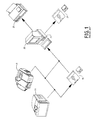
- Fig. 1 is a diagram illustrating a conventional image processing system used to perform image data compression by means of transform image encoding and decoding.
- An original source image is converted into a digital source image comprising image data terms by means of an image digitizer, such as an optical scanner 11 or a video camera 13.
- the image data terms are either stored by means of an image-data disc 15 or similar storage medium, or sent directly to a transform image coding unit 21 for conversion into compressed image data.
- transform image coding unit 21 subsequently reconstructs a digital image which is sent to an image output unit such as a monitor 23 or a printing device 25.
- the compressed image data can be stored within unit 21, or be archived onto a compressed-data disc 27, or be transmitted to a remote image processing system for image reconstruction.
- an image encoding module 35 and an image decoding module 37 perform the image data compression and decoding functions of a conventional transform image coding unit.
- An image digitizer 10 converts an original source image 31 into one or more sets of color-band data, each of which is separately identified as a digital source image 33.
- Digital source image 33 is provided to image encoding module 35 as a two-dimensional H ⁇ V set of image data terms.
- Image encoding module 35 transforms digital source image 33 into compressed image data which is transmitted to image decoding module 37 by means of a transmission medium 19, which can be an electronic network or other communication system.
- the compressed image data is received by image decoding module 37 which transforms the compressed image data into a reduced-noise digital image 39.
- An image output unit 20 converts reduced-noise digital image 39 into a reconstructed reduced-noise image 41.
- compressed image data produced by image encoding module 35 may be stored or archived in an interim storage medium 29, such as a magnetic disc, before being sent on to image decoding module 37.
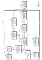
- Digital source image 33 comprises an H ⁇ V set of image data terms, denoted by s 0 (z,y). This set of image data terms is divided into a two-dimensional array ofN ⁇ N image-data matrices 51 as is well-known in the art. Each image-data matrix 51 comprises N 2 terms denoted by s(j,i), where 0 ⁇ i,j ⁇ N-1.
- the frequency coefficient terms S( ⁇ , ⁇ ) in frequency-coefficient matrix 53 are each divided by a corresponding scaled quantization term Q( ⁇ , ⁇ ), at operation 62, where the scaled quantization term is obtained from an N ⁇ N quantization table 73 used in conjunction with a scaling factor 71, denoted here as K.
- the degree of image data compression performed by image encoding module 35 is proportional to the value of scaling factor 71.
- the value of scaling factor 71 is also used to determine the numerical values for filter parameters ⁇ k and ⁇ k , which are obtained from a look-up table in filter parameter set 75.
- Table I specifies filter parameters ⁇ k and ⁇ k for image-data bands y, u, and v, when a value for ⁇ is given or determined.
- Filter parameter set 75 is transmitted to image decoding module 37 for use in the attenuation of quantization noise, as described in greater detail below.
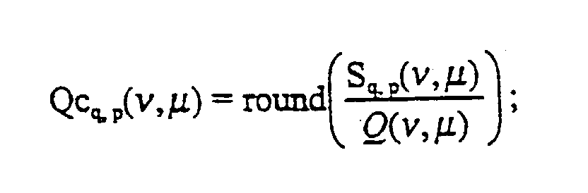
- the quotient terms Qu q,p ( ⁇ , ⁇ ) are rounded to less precise values, at operation 63, to yield quantized-coefficient matrices 57 comprising quantized-quotient terms Qc q,p ( ⁇ , ⁇ ) given by the expression
- Difference-coefficient matrix 77 contains difference terms Dc q,p ( ⁇ , ⁇ ) obtained by subtracting each quantized-quotient term Qc q,p ( ⁇ , ⁇ ) in quantized-coefficient matrix 57 from the corresponding quotient term Qu q,p ( ⁇ , ⁇ ) in quotient-coefficient matrix 55 in accordance with the equation,
- a series of difference-coefficient matrices 77 are derived, one for each frequency-coefficient matrix 53 in the matrix array.
- the difference-coefficient matrices 77 are summed, averaged, and multiplied by a corresponding quantization term, at operation 66, to produce an N ⁇ N quantization error matrix 79 comprising terms E 0 ( ⁇ , ⁇ ) derived in accordance with the equation, where M is the total number of difference-coefficient matrices 77 summed.
- quantization error matrix 79 comprises terms E 1 ( ⁇ , ⁇ ) derived as root-mean-square error terms in accordance with the equation,
- Each quantized-coefficient matrix 57 is transmission-encoded, at operation 64, by a process such as zig-zag sequencing with Huffman encoding, to yield a transmission-encoded data set 59.
- Transmission-encoded data set 59 is then transmitted to image decoding module 37 via transmission medium 19.
- Quantization error matrix 79, filter parameter set 75, and quantization table 73 are similarly transmitted to image decoding module 37 via transmission medium 19.
- Transmission-encoded data set 59 is decoded into a set of received quantized transform coefficients, denoted by Sr q,p ( ⁇ , ⁇ ).
- Execution of operation 91 yields a series of N ⁇ N received coefficient matrices 81 comprising mask-multiplied transform coefficients R q,p ( ⁇ , ⁇ ), where each transform coefficient R q,p ( ⁇ , ⁇ ) corresponds to a quantized-quotient term Qc q,p ( ⁇ , ⁇ ) previously processed in image encoder module 35.
- Each received image data term r q,p (j,i) corresponds to an image data term s 0 (z,y) from H ⁇ V digital source image 33. Accordingly, received image data terms r q,p (j,i) can be formatted into an H ⁇ V received image-data set 83 comprising terms denoted by s R (z,y).
- received image data set 83 would next be reconstructed, at conventional operation 93, to form a received digital image 43, denoted by phantom lines. It is received digital image 43 which commonly exhibits blocking artifacts at moderate to high ratios of image compression. The blocking artifacts result from errors introduced by the quantization of quotient terms at operation 63 in image encoding module 35.
- One procedure employed to solve this problem of quantization noise is to reduce scaling factor 71 such that the quantization performed on the quotient terms is decreased and the occurrence of blocking artifacts is reduced.
- this approach is undesirable because a lesser degree of image data compression results and the computational resources and transmission time required to process the compressed data are correspondingly increased.
- the present invention suppresses or eliminates the occurrence of blocking artifacts by means of a corrective process which compensates for the errors introduced by the prior quantization operation.
- the terms s R (z,y) comprising received image-data set 83 are modified by a filtering process before a digital image is reconstructed.
- the filtering is accomplished by means of the following sequence of operations: i) overlap-transforming the terms s R (z,y) of received image-data set 83 into the frequency domain to form a two-dimensional array of N ⁇ N modified frequency-coefficient matrices 85, at operation 94, ii) filtering the modified frequency-coefficient matrices 85 to produce a series of filtered coefficient matrices 87, at operation 95, iii) inverse transforming the filtered coefficient matrices 87 into the spatial domain to produce a filtered image-data matrix 88, at operation 96, iv) extracting selected reduced-noise terms from filtered image-data matrices 88, to form a two-dimensional H ⁇ V reduced noise image-data set 89 at operation 98, and v) forming reduced-noise digital image 39 from reduced-noise image-data set 89, at operation 99.
- Overlap-transformation of received image-data set 83 refers to the process of applying a forward orthogonal transformation to an array of N ⁇ N matrices which have been obtained from image-data set 83 by an 'overlap' process.
- the image data terms comprising the overlapped image-data matrix in the r-th column and s-th row of the overlapped image-data matrix array are denoted by v s,r (j,i).
- the amount of overlap used in the overlap procedure is determined by the value of integer constant ⁇ , which is an overlap parameter 84 provided by image decoding module 37.
- ⁇ is set to N / 2. It can be seen that application of the overlapping process results in a matrix array in which certain rows and columns of image data terms are common to corresponding pairs of overlapped image data matrices.
- a filtering computation, utilizing filter parameter set 75 and quantization error matrix 79, is performed upon the modified coefficient matrices, at operation 95, to yield N ⁇ N filtered coefficient matrices 87, comprising filtered frequency-coefficient terms Sf s,r ( ⁇ , ⁇ ), obtained in accordance with the equation
- Numerical values for ⁇ and ⁇ are obtained from filter parameter set 75 and E X ( ⁇ , ⁇ ) is quantization error matrix 79, such as E 0 ( ⁇ , ⁇ ) or E 1 ⁇ , ⁇ ) defined above.
- Each core submatrix rk s,r (m,n) is obtained by deleting the image data terms in rows 0 through ( ⁇ / 2-1) and (N- ⁇ / 2) through (N-1), and the filtered image data terms in columns 0 through ( ⁇ / 2-1) and (N- ⁇ / 2) through (N-1) of a corresponding filtered image data matrix rf s,r (j,i).
- the relationship between core submatrix terms rk s,r (n,m) and filtered image data terms in the corresponding filtered image-data matrix rf s,r (j,i) is given by the expression, for
- Reduced-noise image-data set 89 which corresponds to received image-data set 83, is reconstructed, at operation 99, to form reduced-noise digital image 39.
- the effects of blocking artifacts attributable to quantization have been reduced or eliminated in reduced-noise digital image 39 as a consequence of filtering operation 95.
- image decoding is accomplished by means of an alternative image decoding module 101, shown in Fig. 5.
- the conventional image encoding module provides a quantization table 105, but no quantization error matrix or filter parameters, via transmission medium 19.
- image decoding module 101 utilizes a quantization error table 109 as a quantization error matrix, in operation 95.
- Filtering parameters used in operation 95 are provided by obtaining numerical values for ⁇ k and ⁇ k from a filter parameter set 75' by means of a decoding parameter table, such as Table II.
- Transmission encoded data set 103 is converted into a series of modified coefficient matrices 85, by means of operations 92 and 94, as described above for the preferred embodiment.
- An estimated scaling factor 107 denoted by ⁇ ', is obtained as the DC scaled quantization term (i.e., scaled quantization term Q(0,0)in the first row and first column) of quantization table 105, at operation 121.
- Scaling factor 107 is applied to filter parameter set 75' to produce numerical values for ⁇ k and ⁇ k in accordance with Table II.
- Scaling factor 107 is also applied to quantization-error table 109 from which an estimated quantization error matrix E ⁇ ( ⁇ , ⁇ ), comprising a table of N ⁇ N noise-mask terms, is selected.
- the noise-mask terms contained in quantization error matrices E ⁇ ( ⁇ , ⁇ ) are derived from empirical data and estimation methods and take into account various image attributes typically considered by an image processing operator.
- Quantization Error Tables III through V are examples of such empirically-derived noise masks used for 8 ⁇ 8 frequency-coefficient matrices.
- Estimated quantization error matrix E ⁇ ( ⁇ , ⁇ ) and the numerical values obtained for ⁇ k and ⁇ k from filter parameter set 75' are applied with the filtering operation performed on modified coefficient matrix 85, at operation 95, to produce filtered coefficient matrix 87.
- Reduced-noise digital image 39 is obtained by execution of operations 96, 98, and 99, as in the preferred embodiment.
- the present invention is advantageously adapted to provide an apparatus which accomplishes moderate levels of image data compression without incurring blocking artifacts in a more efficient method than is presently available in conventional image processing devices. While there have been described preferred embodiments of the present invention, it will be readily apparent to those skilled in the art that various changes and modifications may be made therein without departing from the invention, and it is intended in the wording of the appended claims to include such changes and modifications as would be encompassed by the true spirit and scope of the invention.
Landscapes
- Engineering & Computer Science (AREA)
- Multimedia (AREA)
- Signal Processing (AREA)
- Compression Or Coding Systems Of Tv Signals (AREA)
- Compression Of Band Width Or Redundancy In Fax (AREA)
- Image Processing (AREA)
- Compression, Expansion, Code Conversion, And Decoders (AREA)
Claims (29)
- Verfahren zur Verminderung der Wirkungen blockierender Bildfehler, die auftreten als Folge einer Quantisierung bei der Transformationsbild-Kodierung und Kompression eines zweidimensionalen Bildsignals in ein digitales Bild, wobei das Ausmaß der Kompression durch einen Skalierungsfaktor κ und eine Quantisierungstabelle bestimmt wird, und wobei das Bildsignal in Form einer Reihe elektrischer Signale vorhanden ist und jedes elektrische Signal einer Charakteristik eines Elementes eines zweidimensionalen Bildes entspricht und wobei die Bildelemente als zweidimensionales H x V-Feld ausgebildet sind und wobei das Verfahren die folgenden Schritte umfaßt:Es wird eine Reihe elektrischer Signale in eine Gruppe numerischer Werte umgewandelt, wobei jeder numerische Wert quantitativ eine Merkmals-Charakteristik eines entsprechenden Bildelementes beschreibt und die numerischen Werte weiter durch s0(z,y) beschrieben sind, wobei 0 ≤ y ≤ H-1 und 0 ≤ z ≤ V-1;es wird die Gruppe numerischer Werte in eine Mehrzahl von N x N-Bilddatenmatrizen formatiert, die identifiziert sind durch Indizes "p" und "q", wobei jede Bilddatenmatrix Bilddatenausdrücke aufweist, die mit sq,p(j,i) bezeichnet sind und jeder Bilddatenausdruck aus einem numerischen Wert besteht, der gemäß der folgenden Beziehung bestimmt ist:es wird jede Bilddatenmatrix in eine N x N-Frequenz-Koeffizienten-Matrix transformiert, die Frequenz-Koeffizienten-Ausdrücke aufweist, die mit Sq,p(ν,µ) bezeichnet sind, wobei der Schritt der Transformation einer jeden Bilddatenmatrix mittels einer orthogonalen Transformations-Basismatrix C gemäß dem folgenden Ausdruck durchgeführt wird:es wird jeder Frequenz-Koeffizienten-Ausdruck Sq,p(ν,µ) durch einen skalierten Quantisierungsausdruck dividiert, der mit Q(ν,µ) bezeichnet ist, wobei der skalierte Quantisierungsausdruck aus der Quantisierungstabelle entnommen und durch den Skalierungsfaktor modifiziert wird, um mehrere N x N-Quotienten-Koeffizienten-Matrizen zu bilden, die Quotientenausdrücke umfassen, welche mit Quq,p(ν,µ) bezeichnet sind und gemäß dem folgenden Ausdruck abgeleitet wurdenes wird jeder Quotientenausdruck auf einen weniger präzisen Wert abgerundet, um eine quantisierte Koeffizientenmatrix zu schaffen, die quantisierte Quotientenausdrücke umfaßt, die mit Qcq,p(ν,µ) gemäß dem folgenden Ausdruck bezeichnet sind
 es wird jeder quantisierte Koeffizientenausdruck Qcq,p(ν,µ) von einem entsprechenden Quotientenausdruck Quq,p(ν,µ) subtrahiert, um mehrere N x N-Differenz-Koeffizienten-Matrizen zu schaffen, die Differenzausdrücke Dcq,p(ν,µ) umfassen, wel che gemäß dem folgenden Ausdruck abgeleitet sind:
 es wird eine Quantisierungs-Fehlermatrix abgeleitet, die die Ausdrücke E0(ν,µ) umfaßt, indem Fehlerausdrücke summiert und zu einem Durchschnittswert zusammengefaßt werden, wobei die Fehlerausdrücke Funktionen der Differenz-Koeffizienz-Matrizen umfassen;es wird eine Gruppe von Filterparametern gewählt, die mit α und β bezeichnet sind;es wird jeder quantifizierte Koeffizientenausdruck mit einem entsprechenden Quantisierungsausdruck multipliziert, um mehrere N x N-maskenmultiplizierte Transformations-Koeffizienten-Matrizen zu bilden, die Ausdrücke umfassen, welche mit Rq,p(ν,µ) bezeichnet sind und gemäß der folgenden Beziehung abgeleitet wurdenes wird eine inverse orthogonale Transformation der maskenmultiplizierten Transformations-Koeffizienten-Matrizen durchgeführt, um mehrere N x N-Empfangsbild-Datenmatrizen zu schaffen, die mit rq,p(j,i) bezeichnet sind und gemäß der folgenden inversen Transformationsgleichung abgeleitet wurdenes werden die Empfangsbild-Datenmatrizen in eine H x V-Empfangsbild-Datengruppe formatiert, welche Ausdrücke umfaßt, die mit SR(z,y) bezeichnet sind und gemäß der folgenden Gleichung gebildet sind;es wird die Empfangsbild-Datengruppe in mehrere überlappende N x N-Bilddatenmatrizen umgeformt, die Ausdrücke umfassen, welche mit vs,r(j,i) bezeichnet sind und gemäß der folgenden Gleichung gewonnen wurdenes werden die überlappenden Bilddatenmatrizen in modifizierte Koeffizientenmatrizen transformiert, welche Ausdrücke umfassen, die mit Svs,r(ν,µ) bezeichnet sind und gemäß der folgen den Gleichung gewonnen wurdenes werden die modifizierten Koeffizientenmatrizen in gefilterte Koeffizientenmatrizen durch die Quantisierungs-Fehlermatrix und die Filterparameter in gefilterte Koeffizientenmatrizen umgeformt und die modifizierte Koeffizientenmatrix umfaßt Ausdrücke, die mit Sfs,r(ν,µ) bezeichnet sind, wobei der Schritt der Umwandlung der modifizierten Koeffizientenmatrizen gemäß der folgenden Gleichung durchgeführt wird:
 es werden die gefilterten Koeffizientenmatrizen in gefilterte Bilddatenmatrizen gemäß der folgenden Gleichung transformiert:es werden die gefilterten Bilddatenmatrizen in einer Reihe gefilterter elektrischer Signale umgewandelt, derart, daß die gefilterten elektrischen Signale in ein zweidimensionales H x V-Feld gefilterter Bildelemente konfiguriert werden können und das gefilterte elektrische Signal einer Charakteristik eines der gefilterten Bildelemente entspricht.
 - Verfahren nach Anspruch 1, bei welchem die Quantisierungs-Fehlermatrix E0(ν,µ) gemäß der folgenden Beziehung bestimmt wird:
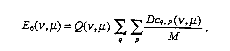
- Verfahren nach Anspruch 1, bei welchem die Quantisierungs-Fehlermatrix E0(ν,µ) gemäß der folgenden Beziehung bestimmt wird:

- Verfahren nach Anspruch 1, bei welchem die orthogonale Transformations-Basismatrix C eine diskrete Cosinus-Transformations-Basismatrix umfaßt.
- Verfahren nach Anspruch 1, bei welchem der Schritt der Umwandlung der gefilterten Bilddatenmatrizen den Schritt umfaßt, eine Kern-Submatrix aus jeder gefilterten Bilddatenmatrix zu extrahieren und mehrere der Kern-Submatrizen zu kombinieren, um das zweidimensionale H x V-Feld gefilterter Bildelemente zu erzeugen.
- Verfahren nach Anspruch 5, bei welchem der Schritt der Extrahierung einer Kern-Submatrix das Löschen der Bilddatenausdrücke in den Zeilen 0 bis ( ω / 2-1) und (N- ω / 2) bis (N-1) der gefilterten Bilddatenmatrizen umfaßt und außerdem das Löschen der gefilterten Bilddatenausdrücke in den Spalten 0 bis ( ω / 2-1) und (N- ω / 2) bis (N-1) der gefilterten Bilddatenmatrix.
- Verfahren nach Anspruch 1, bei welchem ω auf N / 2 gesetzt wird.
- Verfahren nach Anspruch 1, bei welchem N gleich 8 ist.
- Verfahren zur Verminderung der Wirkungen von Blockierungs-Bildfehlern, die als Folge einer Quantisierung bei der Übertragungsbild-Kodierung und Kompression eines zweidimensionalen Bildsignals in ein digitales Bild auftreten, wobei das Ausmaß der Kompression bestimmt wird durch einen Skalierungsfaktor κ und eine Quantisierungstabelle und das Bildsignal als eine Reihe elektrischer Signale vorgesehen ist, wobei jedes elektrische Signal einer Charakteristik eines Elementes eines zweidimensionalen Bildes entspricht und wobei die Bildelemente als zweidimensionales H x V-Feld konfiguriert sind und wobei das Verfahren die folgenden Schritte aufweist:Es wird die Bildkodierung des zweidimensionalen H x V-Feldes von Bildelementen transformiert, um eine kodierte Bilddatengruppe durch eine orthogonale Transformations-Basismatrix zu erhalten, wobei der Schritt der Transformation der Bildkodierung eine Quantisierungsoperation umfaßt;es wird die kodierte Bilddatengruppe durch die orthogonale Transformations-Basismatrix dekodiert, um eine dekodierte Bilddatengruppe zu erhalten;es wird die dekodierte Bilddatengruppe in mehrere Frequenz-Koeffizienz-Ausdrücke durch die orthogonale Transformations-Basismatrix umgewandelt;die Ausdrücke SR(z,y), die die empfangene Bilddatengruppe (83) umfassen, werden durch einen Filterprozeß modifiziert, bevor ein digitales Bild rekonstruiert wird;die Filterung wird mittels der nachstehenden Operationsfolge durchgeführt:i) es werden die Ausdrücke SR(z,y) der empfangenen Bilddatengruppe (83) überlappt transformiert in die Frequenzdomäne, um ein zweidimensionales Feld von N x N modifizierten Frequenz-Koeffizienz-Matrizen (85) während einer Operation (94) zu erhalten;ii) es werden die modifizierten Frequenz-Koeffizienz-Matrizen (85) gefiltert, um eine Reihe von gefilterten Koeffizienzmatrizen (87) während der Operation (95) zu erzeugen;iii) es erfolgt eine inverse Transformation der gefilterten Koeffizienzmatrizen (87) in die räumliche Domäne, um eine gefilterte Bilddatenmatrix (88) während der Operation (96) zu erhalten;iv) es werden gewählte rauschverminderte Ausdrücke aus gefilterten Bilddatenmatrizen (88) extrahiert, um eine zweidimensionale H x V-Bilddatengruppe (89) mit vermindertem Rauschpegel in der Operation (98) zu erhalten; undv) es wird ein rauschvermindertes Digitalbild (39) aus der rauschreduzierten Bilddatengruppe (89) während einer Operation (99) gebildet.
- Verfahren zur Filterung eines zweidimensionalen dekodierten Bildsignals in der Weise, daß die Wirkungen von blockierenden Bildfehlern als Folge der Quantisierung vermindert werden, wobei die blockierenden Bildfehler in dem dekodierten Bildsignal als Folge davon auftreten, daß eine Transformationsbild-Kodierung und Datenkompression und Quantisierung des vorangegangenen Bildsignals stattgefunden hat, wobei das vorangegangene Bildsignal als eine Reihe von elektrischen Signalen geliefert wurde und jedes elektrische Signal einer Charakteristik eines Elementes des vorhergehenden Bildes entspricht, und wobei die Kompressionsoperation einen Skalierungsfaktor K und Quantisierungsausdrücke benutzt, die aus einer Quantisierungstabelle abgeleitet werden, und wobei das dekodierte Bildsignal als eine zweidimensionale H x V-Gruppe von Bilddatenausdrücken gestaltet wurde, die mit SR(z,y) bezeichnet sind, wobei das Verfahren die nachstehenden Schritte aufweist:es wird ein Überlappungsparameter definiert, der mit ω bezeichnet wird;es wird eine dekodierte Bildsignalgruppe in einer Mehrzahl von überlappten N x N-Bilddatenmatrizen erzeugt, die Ausdrücke umfassen, welche mit vs,r(j,i) gemäß der folgenden Beziehung bezeichnet sindes werden die überlappten Bilddatenmatrizen in modifizierte Koeffizientenmatrizen transformiert, die Ausdrücke umfassen, welche mit Svs,r(ν,µ) bezeichnet sind, wobei die Transformation durch eine orthogonale Transformations-Basismatrix C gemäß der folgenden Matrixgleichung bewirkt wird:es wird ein Skalierungsfaktor κ berechnet;es wird ein Filterparameter als Funktion des Skalierungsfaktors bestimmt, wobei die Filterparameter mit α(κ) und β(κ) bezeichnet sind;es wird eine Quantisierungs-Fehlermatrix gewählt, die mit E0 bezeichnet wird;es werden die modifizierten Koeffizientenmatrizen in gefilterte Koeffizientenmatrizen mittels der quantisierten Fehlermatrix und mittels der Filterparameter umgeformt, wobei die modifizierte Koeffizientenmatrix Ausdrücke enthält, die mit Sfs,r(ν,µ) bezeichnet sind und wobei der Schritt der Umwandlung der modifizierten Koeffizientenmatrizen gemäß der folgenden Gleichung durchgeführt wird:
 es werden die gefilterten Koeffizientenmatrizen in gefilterte Bilddatenmatrizen transformiert, die mit rfs,r(j,i) gemäß der folgenden Matrixgleichung bezeichnet sind:es werden die gefilterten Bilddatenmatrizen in einer Reihe gefilterter elektrischer Signale umgewandelt, und zwar derart, daß die gefilterten elektrischen Signale in einem zweidimensionalen H x V-Feld gefilterter Bildelemente konfiguriert werden können, um ein rauschreduziertes Digitalbild zu erzeugen, wobei jedes gefilterte elektrische Signal einer Charakteristik des gefilterten Bildelementes entspricht.
 - Verfahren nach Anspruch 10, bei welchem die orthogonale Transformations-Basismatrix C eine diskrete Cosinus-Transformations-Basismatrix umfaßt.
- Verfahren nach Anspruch 10, bei welchem der Schritt der Umwandlung der gefilterten Bilddatenmatrizen den Schritt umfaßt, eine Kern-Submatrix aus jeder gefilterten Bilddatenmatrix abzuziehen und diese mit mehreren der Kern-Submatrizen zu kombinieren, um eine zweidimensionale H x V-Bilddatengruppe mit vermindertem Rauschen zu erzeugen, aus der das rauschreduzierte digitale Bild erzeugt wird.
- Verfahren nach Anspruch 12, bei welchem der Schritt der Extraktion einer Kern-Submatrix ein Löschen der BilddatenAusdrücke in den Zeilen 0 bis ( ω / 2-1) und (N- ω / 2) bis (N-1) der gefilterten Bilddatenmatrix und ein Löschen der gefilterten Bilddaten-Ausdrücke in den Spalten 0 bis ( ω / 2-1) und (N- ω / 2) bis (N-1) der gefilterten Bilddatenmatrix umfaßt.
- Verfahren nach Anspruch 10, bei welchem ω auf N / 2 gesetzt ist.
- Verfahren nach Anspruch 10, bei welchem der Schritt der Berechnung eines Skalierungsfaktors κ den Schritt umfaßt, κ gleich dem skalierten Gleichstrom-Quantisierungsaudruck der Quantisierungstabelle zu stellen.
- Verfahren nach Anspruch 10, bei welchem der Schritt der Bestimmung der Filterparameter einen Schritt enthält, in dem wenigstens einer der Filterparameter aus einer numerischen Tabelle erlangt wird.
- Verfahren nach Anspruch 10, bei welchem κ ≤ gleich 8 und α(κ) = β(κ) = 0 ist.
- Verfahren nach Anspruch 10, bei welchem 8 < κ ≤ 24 und α(κ), β(κ) ≤ 1 ist.
- Verfahren nach Anspruch 10, bei welchem 24 < κ ≤ 32 und α(κ), β(κ) ≥ 2 ist.
- Verfahren nach Anspruch 10, bei welchem κ >32 und α(κ), β(κ) ≥ 3 ist.
- Verfahren nach Anspruch 10, bei welchem der Schritt der Wahl einer Quantisierungs-Fehlermatrix einen Schritt enthält, bei dem wenigstens ein Quantisierungs-Fehlerausdruck aus einer numerischen Tabelle entnommen wird.
- Vorrichtung zur Verminderung der Wirkungen von Blockierungs-Farbfehlern als Folge einer Quantifizierung, die während der Bildkodierungs-Transformation und Kompression eines zweidimensionalen Bildsignals in ein digitales Bild auftrat, wobei das Ausmaß der Kompression durch einen Skalierungsfaktor und eine Quantisierungstabelle bewirkt wird und das Bildsignal in Form einer Reihe elektrischer Signale geliefert wird, wobei jedes elektrische Signal einer Charakteristik eines Elementes eines zweidimensionalen Bildes entspricht und wobei die Bildelemente als zweidimensionales H x V-Feld ausgebildet sind, wobei die Vorrichtung die folgenden Merkmale aufweist:es sind Mittel vorgesehen, um eine orthogonale Transformations-Basismatrix dem zweidimensionalen H x V-Feld von Bildelementen aufzuprägen, um so eine kodierte Bilddatengruppe zu erzeugen, die quantisierte Ausdrücke enthält;es sind Mittel vorgesehen, um die orthogonale Transformations-Basismatrix der kodierten Bilddatengruppe so zuzuführen, daß eine dekodierte Bilddatengruppe gebildet wird;es sind Mittel vorgesehen, um die Bildkodierung der dekodierten Bilddatengruppe in mehrere Frequenz-Koeffizienz-Ausdrücke zu transformieren;es sind Filter vorgesehen, die in der nachstehenden Arbeitsfolge wirken:i) es erfolgt eine Überlappungs-Transformation der Ausdrücke SR(z,y) der empfangenen Bilddatengruppe (83) in die Frequenzdomäne, um ein zweidimensionales Feld von N x N-modifizierten Frequenz-Koeffizienten-Matrizen (85) mit der Operation (94) durchzuführen;ii) es werden die modifizierten Frequenz-Koeffizienten-Matrizen (85) gefiltert, um eine Reihe gefilterter Koeffizienzmatrizen (87) mit der Operation (95) zu erzeugen;iii) es werden die gefilterten Koeffizienzmatrizen (87) invers in die räumliche Domäne transformiert, um eine gefilterte Bilddatenmatrix (88) mit der Operation (96) zu erzeugen;iv) es werden gewählte rauschreduzierte Ausdrücke aus gefilterten Bilddatenmatrizen (88) abgezogen, um eine zweidimensionale rauschreduzierte H x V-Bilddatengruppe (89) mit der Operation (98) zu bilden; undv) es wird ein rauschreduziertes digitales Bild (39) mit der Operation (99) aus der rauschreduzierten Bilddatengruppe (89) gebildet.
- Vorrichtung zur Bildverarbeitung nach Anspruch 22, bei welcher die Mittel zur Transformation der Bildkodierung der dekodierten Bilddatengruppe Mittel umfassen, um die dekodierte Bilddatengruppe in ein Feld überlappter Bilddatenmatrizen umzuformen, und es sind Mittel vorgesehen, um die Bildkodierung des Feldes überlappter Bilddatenmatrizen in ein Feld von Frequenz-Koeffizienten-Matrizen zu transformieren, die die Frequenz-Koeffizienten-Ausdrücke enthalten.
- Vorrichtung zur Bildverarbeitung nach Anspruch 22, welche außerdem Mittel aufweist, um den Koeffizienz-Filterausdruck abzuleiten.
- Vorrichtung zur Bildverarbeitung nach Anspruch 24, bei welcher die Mittel zur Ableitung des Koeffizienten-Filterausdrucks Mittel umfassen, um eine Quantisierungs-Fehlermatrix zu erzeugen.
- Vorrichtung zur Bildverarbeitung nach Anspruch 25, bei welcher die Mittel zur Erzeugung einer Quantisierungs-Fehlermatrix eine numerische Tabelle enthalten.
- Vorrichtung zur Bildverarbeitung nach Anspruch 22, bei welcher die orthogonale Transformations-Basismatrix eine diskrete Cosinus-Transformations-Basismatrix aufweist.
- Vorrichtung zur Bildverarbeitung nach Anspruch 22, bei welcher die Mittel zur Umwandlung der gefilterten Frequenzkoeffizienten Mittel aufweisen, die die Bildkodierung der gefilterten Frequenzkoeffizienten in gefilterte Bilddatenausdrücke umwandeln und außerdem Mittel zur Umwandlung der gefilterten Bilddatenausdrücke in einer Reihe gefilterter elektrischer Signale derart, daß die gefilterten elektrischen Signale in einem zweidimensionalen H x V-Feld gefilterter Bildelemente konfiguriert werden können, um das rauschreduzierte digitale Bild zu erzeugen, wobei jedes der gefilterten elektrischen Signale einer Charakteristik eines gefilterten Bildelementes entspricht.
- Vorrichtung zur Bildverarbeitung nach Anspruch 28, bei welcher die Mittel zur Umwandlung der gefilterten Bilddatenausdrücke Mittel umfassen, um einen Teil der gefilterten Bilddatenausdrücke abzuziehen und außerdem Mittel, um jenen Teil zu kombinieren, um eine zweidimensionale rauschreduzierte H x V-Bilddatengruppe zu erzeugen, aus der das rauschreduzierte digitale Bild erzeugt wird.
Applications Claiming Priority (3)
| Application Number | Priority Date | Filing Date | Title |
|---|---|---|---|
| US441372 | 1982-11-12 | ||
| US08/441,372 US5629778A (en) | 1995-05-15 | 1995-05-15 | Method and apparatus for reduction of image data compression noise |
| PCT/US1996/006888 WO1996037077A1 (en) | 1995-05-15 | 1996-05-15 | Method and apparatus for reduction of image data compression noise |
Publications (2)
| Publication Number | Publication Date |
|---|---|
| EP0771507A1 EP0771507A1 (de) | 1997-05-07 |
| EP0771507B1 true EP0771507B1 (de) | 2000-01-12 |
Family
ID=23752623
Family Applications (1)
| Application Number | Title | Priority Date | Filing Date |
|---|---|---|---|
| EP96920209A Expired - Lifetime EP0771507B1 (de) | 1995-05-15 | 1996-05-15 | Verfahren und vorrichtung zur rauschunterdrückung in komprimierten bilddaten |
Country Status (8)
| Country | Link |
|---|---|
| US (1) | US5629778A (de) |
| EP (1) | EP0771507B1 (de) |
| JP (1) | JPH10503359A (de) |
| KR (1) | KR970705306A (de) |
| AT (1) | ATE188829T1 (de) |
| CA (1) | CA2194574A1 (de) |
| DE (1) | DE69606139T2 (de) |
| WO (1) | WO1996037077A1 (de) |
Cited By (2)
| Publication number | Priority date | Publication date | Assignee | Title |
|---|---|---|---|---|
| DE102004063300A1 (de) * | 2004-12-29 | 2006-07-20 | Julius-Maximilians-Universität Würzburg | Verfahren und Einrichtung zum Beurteilen einer durch Detektion einer physikalischen Größe aufgenommenen Funktion |
| US8885706B2 (en) | 2011-09-16 | 2014-11-11 | Google Inc. | Apparatus and methodology for a video codec system with noise reduction capability |
Families Citing this family (69)
| Publication number | Priority date | Publication date | Assignee | Title |
|---|---|---|---|---|
| US5936673A (en) * | 1995-05-26 | 1999-08-10 | Intel Corporation | Temporal tile staggering for block based video compression |
| SE509641C2 (sv) * | 1996-05-03 | 1999-02-15 | Allgon Ab | En antennanordning försedd med en matchningsanordning |
| US5828467A (en) * | 1996-10-02 | 1998-10-27 | Fuji Xerox Co., Ltd. | Block noise prevention by selective interpolation of decoded image data |
| US7239755B1 (en) * | 1997-07-30 | 2007-07-03 | Lg Electronics Inc. | Method of reducing a blocking artifact when coding moving picture |
| KR100281099B1 (ko) * | 1997-07-30 | 2001-04-02 | 구자홍 | 동영상의부호화에따른블록화현상제거방법 |
| KR100244290B1 (ko) * | 1997-09-09 | 2000-02-01 | 구자홍 | 저속 전송에서의 동영상을 위한 디블록킹 필터링 방법 |
| US6327307B1 (en) * | 1998-08-07 | 2001-12-04 | Motorola, Inc. | Device, article of manufacture, method, memory, and computer-readable memory for removing video coding errors |
| US6317522B1 (en) * | 1998-12-03 | 2001-11-13 | Philips Electronics North America Corp. | Systems and methods for post-processing decompressed images |
| US6970179B1 (en) * | 2000-05-12 | 2005-11-29 | International Business Machines Corporation | Method and apparatus for the scaling up of data |
| US7062098B1 (en) * | 2000-05-12 | 2006-06-13 | International Business Machines Corporation | Method and apparatus for the scaling down of data |
| EP1193649A1 (de) * | 2000-09-28 | 2002-04-03 | Sony International (Europe) GmbH | Qualitätsbewertungsfunktion von diskreten dekodierten angezeigten Bilddaten |
| US6961473B1 (en) * | 2000-10-23 | 2005-11-01 | International Business Machines Corporation | Faster transforms using early aborts and precision refinements |
| US6606418B2 (en) * | 2001-01-16 | 2003-08-12 | International Business Machines Corporation | Enhanced compression of documents |
| US7123655B2 (en) * | 2001-08-09 | 2006-10-17 | Sharp Laboratories Of America, Inc. | Method for reduced bit-depth quantization |
| EP1303143A3 (de) * | 2001-10-16 | 2004-01-14 | Koninklijke Philips Electronics N.V. | Blockeffektdetektionsverfahren |
| JP3853708B2 (ja) * | 2002-07-10 | 2006-12-06 | Necアクセステクニカ株式会社 | デジタル画像符号化装置および符号化方法ならびにプログラム |
| JP3893099B2 (ja) | 2002-10-03 | 2007-03-14 | オリンパス株式会社 | 撮像システムおよび撮像プログラム |
| US7139437B2 (en) * | 2002-11-12 | 2006-11-21 | Eastman Kodak Company | Method and system for removing artifacts in compressed images |
| US7277592B1 (en) * | 2003-10-21 | 2007-10-02 | Redrock Semiconductory Ltd. | Spacial deblocking method using limited edge differences only to linearly correct blocking artifact |
| US7616829B1 (en) | 2003-10-29 | 2009-11-10 | Apple Inc. | Reducing undesirable block based image processing artifacts by DC image filtering |
| US20070248276A1 (en) * | 2004-06-15 | 2007-10-25 | Yoichiro Yahata | Quantization Table Producing Device, Quantization Table Producing Method, Quantization Table Producing Program, Image Compression Device, Image Compression Method and Image Compression Program |
| US7545988B2 (en) * | 2004-08-09 | 2009-06-09 | George William Meeker | Image blocking artifact reduction via transform pair |
| HUE049974T2 (hu) * | 2005-01-07 | 2020-11-30 | Qualcomm Inc | Képeken lévõ objektumok észlelése és követése |
| US9910341B2 (en) | 2005-01-31 | 2018-03-06 | The Invention Science Fund I, Llc | Shared image device designation |
| US9124729B2 (en) | 2005-01-31 | 2015-09-01 | The Invention Science Fund I, Llc | Shared image device synchronization or designation |
| US20060285150A1 (en) * | 2005-01-31 | 2006-12-21 | Searete Llc, A Limited Liability Corporation Of The State Of Delaware | Regional proximity for shared image device(s) |
| US20060173972A1 (en) * | 2005-01-31 | 2006-08-03 | Searete Llc, A Limited Liability Corporation Of The State Of Delaware | Audio sharing |
| US8606383B2 (en) | 2005-01-31 | 2013-12-10 | The Invention Science Fund I, Llc | Audio sharing |
| US20070236505A1 (en) * | 2005-01-31 | 2007-10-11 | Searete Llc, A Limited Liability Corporation Of The State Of Delaware | Resampling of transformed shared image techniques |
| US20060187227A1 (en) * | 2005-01-31 | 2006-08-24 | Jung Edward K | Storage aspects for imaging device |
| US20060187228A1 (en) * | 2005-01-31 | 2006-08-24 | Searete Llc, A Limited Liability Corporation Of The State Of Delaware | Sharing including peripheral shared image device |
| US7920169B2 (en) * | 2005-01-31 | 2011-04-05 | Invention Science Fund I, Llc | Proximity of shared image devices |
| US7876357B2 (en) * | 2005-01-31 | 2011-01-25 | The Invention Science Fund I, Llc | Estimating shared image device operational capabilities or resources |
| US8902320B2 (en) | 2005-01-31 | 2014-12-02 | The Invention Science Fund I, Llc | Shared image device synchronization or designation |
| US9082456B2 (en) | 2005-01-31 | 2015-07-14 | The Invention Science Fund I Llc | Shared image device designation |
| US20060190968A1 (en) * | 2005-01-31 | 2006-08-24 | Searete Llc, A Limited Corporation Of The State Of The State Of Delaware | Sharing between shared audio devices |
| US20060221197A1 (en) * | 2005-03-30 | 2006-10-05 | Jung Edward K | Image transformation estimator of an imaging device |
| US20060170956A1 (en) | 2005-01-31 | 2006-08-03 | Jung Edward K | Shared image devices |
| US20060171603A1 (en) * | 2005-01-31 | 2006-08-03 | Searete Llc, A Limited Liability Corporation Of The State Of Delaware | Resampling of transformed shared image techniques |
| US20060174203A1 (en) | 2005-01-31 | 2006-08-03 | Searete Llc, A Limited Liability Corporation Of The State Of Delaware | Viewfinder for shared image device |
| US9325781B2 (en) | 2005-01-31 | 2016-04-26 | Invention Science Fund I, Llc | Audio sharing |
| US9489717B2 (en) | 2005-01-31 | 2016-11-08 | Invention Science Fund I, Llc | Shared image device |
| US9819490B2 (en) | 2005-05-04 | 2017-11-14 | Invention Science Fund I, Llc | Regional proximity for shared image device(s) |
| US9191611B2 (en) * | 2005-06-02 | 2015-11-17 | Invention Science Fund I, Llc | Conditional alteration of a saved image |
| US8253821B2 (en) * | 2005-10-31 | 2012-08-28 | The Invention Science Fund I, Llc | Degradation/preservation management of captured data |
| US9621749B2 (en) | 2005-06-02 | 2017-04-11 | Invention Science Fund I, Llc | Capturing selected image objects |
| US10003762B2 (en) | 2005-04-26 | 2018-06-19 | Invention Science Fund I, Llc | Shared image devices |
| US9942511B2 (en) | 2005-10-31 | 2018-04-10 | Invention Science Fund I, Llc | Preservation/degradation of video/audio aspects of a data stream |
| US20070222865A1 (en) | 2006-03-15 | 2007-09-27 | Searete Llc, A Limited Liability Corporation Of The State Of Delaware | Enhanced video/still image correlation |
| US9001215B2 (en) | 2005-06-02 | 2015-04-07 | The Invention Science Fund I, Llc | Estimating shared image device operational capabilities or resources |
| US7782365B2 (en) | 2005-06-02 | 2010-08-24 | Searete Llc | Enhanced video/still image correlation |
| US8233042B2 (en) * | 2005-10-31 | 2012-07-31 | The Invention Science Fund I, Llc | Preservation and/or degradation of a video/audio data stream |
| US20070098348A1 (en) * | 2005-10-31 | 2007-05-03 | Searete Llc, A Limited Liability Corporation Of The State Of Delaware | Degradation/preservation management of captured data |
| US8681225B2 (en) | 2005-06-02 | 2014-03-25 | Royce A. Levien | Storage access technique for captured data |
| US8072501B2 (en) * | 2005-10-31 | 2011-12-06 | The Invention Science Fund I, Llc | Preservation and/or degradation of a video/audio data stream |
| US9451200B2 (en) | 2005-06-02 | 2016-09-20 | Invention Science Fund I, Llc | Storage access technique for captured data |
| US8964054B2 (en) * | 2006-08-18 | 2015-02-24 | The Invention Science Fund I, Llc | Capturing selected image objects |
| US9167195B2 (en) * | 2005-10-31 | 2015-10-20 | Invention Science Fund I, Llc | Preservation/degradation of video/audio aspects of a data stream |
| US7872675B2 (en) * | 2005-06-02 | 2011-01-18 | The Invention Science Fund I, Llc | Saved-image management |
| US9076208B2 (en) * | 2006-02-28 | 2015-07-07 | The Invention Science Fund I, Llc | Imagery processing |
| US9093121B2 (en) | 2006-02-28 | 2015-07-28 | The Invention Science Fund I, Llc | Data management of an audio data stream |
| US9967424B2 (en) | 2005-06-02 | 2018-05-08 | Invention Science Fund I, Llc | Data storage usage protocol |
| US20060274153A1 (en) * | 2005-06-02 | 2006-12-07 | Searete Llc, A Limited Liability Corporation Of The State Of Delaware | Third party storage of captured data |
| EP1741389A1 (de) * | 2005-07-06 | 2007-01-10 | Agfa-Gevaert | Verfahren zur Unterdrückung des Einflusses der Variabilität der physikalischen Eigenschaft auf die Leistung der Bildqualität eines digitalen Bildaufnahmesytem |
| US8237801B2 (en) | 2005-08-05 | 2012-08-07 | The Innovation Science Fund I, LLC | Image processing system and communication method |
| US20070203595A1 (en) * | 2006-02-28 | 2007-08-30 | Searete Llc, A Limited Liability Corporation | Data management of an audio data stream |
| US20070120980A1 (en) | 2005-10-31 | 2007-05-31 | Searete Llc, A Limited Liability Corporation Of The State Of Delaware | Preservation/degradation of video/audio aspects of a data stream |
| EP2495974B1 (de) * | 2009-10-30 | 2017-10-25 | Sun Patent Trust | Codierung von quantizierungsmatrizen |
| US10102613B2 (en) | 2014-09-25 | 2018-10-16 | Google Llc | Frequency-domain denoising |
Family Cites Families (19)
| Publication number | Priority date | Publication date | Assignee | Title |
|---|---|---|---|---|
| US4179709A (en) * | 1978-01-10 | 1979-12-18 | Bell & Howell Company | Video information bandwidth compression |
| US4754492A (en) * | 1985-06-03 | 1988-06-28 | Picturetel Corporation | Method and system for adapting a digitized signal processing system for block processing with minimal blocking artifacts |
| US5054103A (en) * | 1987-09-24 | 1991-10-01 | Matsushita Electric Works, Ltd. | Picture encoding system |
| US5162923A (en) * | 1988-02-22 | 1992-11-10 | Canon Kabushiki Kaisha | Method and apparatus for encoding frequency components of image information |
| JP2639176B2 (ja) * | 1990-05-28 | 1997-08-06 | 日本電気株式会社 | 2次元信号符号化復号化方法とその符号化装置・復号化装置 |
| EP0469855B1 (de) * | 1990-07-31 | 1999-12-01 | Fujitsu Limited | Verfahren und Gerät zur Bilddatenverarbeitung |
| US5227875A (en) * | 1990-08-20 | 1993-07-13 | Kabushiki Kaisha Toshiba | System for transmitting encoded image data with quick image expansion and contraction |
| US5303058A (en) * | 1990-10-22 | 1994-04-12 | Fujitsu Limited | Data processing apparatus for compressing and reconstructing image data |
| GB2253318B (en) * | 1991-02-27 | 1994-07-20 | Stc Plc | Image processing |
| JPH0514735A (ja) * | 1991-07-01 | 1993-01-22 | Kubota Corp | 画像処理装置 |
| US5168375A (en) * | 1991-09-18 | 1992-12-01 | Polaroid Corporation | Image reconstruction by use of discrete cosine and related transforms |
| JP2549479B2 (ja) * | 1991-12-06 | 1996-10-30 | 日本電信電話株式会社 | 動き補償フレーム間帯域分割符号化処理方法 |
| JPH05219385A (ja) * | 1992-02-07 | 1993-08-27 | Hudson Soft Co Ltd | 画像圧縮・伸張方法および装置 |
| US5367385A (en) * | 1992-05-07 | 1994-11-22 | Picturetel Corporation | Method and apparatus for processing block coded image data to reduce boundary artifacts between adjacent image blocks |
| JPH05316360A (ja) * | 1992-05-14 | 1993-11-26 | Fuji Xerox Co Ltd | 画像信号の符号化復号装置 |
| KR0148130B1 (ko) * | 1992-05-18 | 1998-09-15 | 강진구 | 블럭킹아티팩트를 억제시키는 부호화/복호화 방법 및 그 장치 |
| US5379122A (en) * | 1992-10-02 | 1995-01-03 | Xerox Corporation | Decompression of standard ADCT-compressed images |
| US5367629A (en) * | 1992-12-18 | 1994-11-22 | Sharevision Technology, Inc. | Digital video compression system utilizing vector adaptive transform |
| WO1995015530A1 (en) * | 1993-11-30 | 1995-06-08 | Polaroid Corporation | Image coding by use of discrete cosine transforms |
-
1995
- 1995-05-15 US US08/441,372 patent/US5629778A/en not_active Expired - Lifetime
-
1996
- 1996-05-15 KR KR1019970700220A patent/KR970705306A/ko not_active Ceased
- 1996-05-15 DE DE69606139T patent/DE69606139T2/de not_active Expired - Fee Related
- 1996-05-15 CA CA002194574A patent/CA2194574A1/en not_active Abandoned
- 1996-05-15 JP JP8534987A patent/JPH10503359A/ja not_active Ceased
- 1996-05-15 WO PCT/US1996/006888 patent/WO1996037077A1/en not_active Ceased
- 1996-05-15 AT AT96920209T patent/ATE188829T1/de not_active IP Right Cessation
- 1996-05-15 EP EP96920209A patent/EP0771507B1/de not_active Expired - Lifetime
Cited By (2)
| Publication number | Priority date | Publication date | Assignee | Title |
|---|---|---|---|---|
| DE102004063300A1 (de) * | 2004-12-29 | 2006-07-20 | Julius-Maximilians-Universität Würzburg | Verfahren und Einrichtung zum Beurteilen einer durch Detektion einer physikalischen Größe aufgenommenen Funktion |
| US8885706B2 (en) | 2011-09-16 | 2014-11-11 | Google Inc. | Apparatus and methodology for a video codec system with noise reduction capability |
Also Published As
| Publication number | Publication date |
|---|---|
| EP0771507A1 (de) | 1997-05-07 |
| CA2194574A1 (en) | 1996-11-21 |
| DE69606139D1 (de) | 2000-02-17 |
| JPH10503359A (ja) | 1998-03-24 |
| DE69606139T2 (de) | 2000-06-21 |
| US5629778A (en) | 1997-05-13 |
| WO1996037077A1 (en) | 1996-11-21 |
| ATE188829T1 (de) | 2000-01-15 |
| KR970705306A (ko) | 1997-09-06 |
Similar Documents
| Publication | Publication Date | Title |
|---|---|---|
| EP0771507B1 (de) | Verfahren und vorrichtung zur rauschunterdrückung in komprimierten bilddaten | |
| US6493023B1 (en) | Method and apparatus for evaluating the visual quality of processed digital video sequences | |
| US5737451A (en) | Method and apparatus for suppressing blocking artifacts in block-transform coded images | |
| EP0577363B1 (de) | Kompression und Wiederaufbau von radiologischen Bildern | |
| EP0763925B1 (de) | Bildcodierung mit Optimierung der erzeugten Codemenge | |
| US5563718A (en) | Image coding by use of discrete cosine transforms | |
| US5930397A (en) | Apparatus and method for processing image signal | |
| US5675666A (en) | Image data compression method and apparatus with pre-processing to compensate for the blocky effect | |
| US4703349A (en) | Method and apparatus for multi-dimensional signal processing using a Short-Space Fourier transform | |
| JPH10150663A (ja) | ブロッキング効果の最小化方法及び最小化装置 | |
| KR100271994B1 (ko) | 고속2차원코사인변환필터링방법및그장치 | |
| EP0842586A1 (de) | Jpeg-kompressionsschaltung mit filterung | |
| EP1320267B1 (de) | Verfahren zur Kompression von im Farbfilteranordnungsformat (CFA) aufgenommenen digitalen Bildern | |
| EP0714210A2 (de) | Verfahren zum Vermindern von während einer Bilddatendekodierung erzeugtem Mückenrauschen und Vorrichtung zur Dekodierung von ein solches Verfahren verwendenden Bilddaten | |
| US6934420B1 (en) | Wave image compression | |
| WO1995015530A1 (en) | Image coding by use of discrete cosine transforms | |
| Breeuwer et al. | Overlapped transform coding of medical x-ray images | |
| Breeuwer et al. | Data compression of x-ray cardio-angiographic image series | |
| JP2922598B2 (ja) | 画像符号化方式 | |
| US6360018B1 (en) | Image processing apparatus and method | |
| JPH09214967A (ja) | 画像データ圧縮処理方法 | |
| CN1154193A (zh) | 用于降低图象数据压缩噪声的方法和设备 | |
| JP3260008B2 (ja) | 画像データ圧縮処理方法 | |
| JP3282136B2 (ja) | 画像データ圧縮処理方法 | |
| JP2776425B2 (ja) | セル廃棄補償画像復号化方式 |
Legal Events
| Date | Code | Title | Description |
|---|---|---|---|
| PUAI | Public reference made under article 153(3) epc to a published international application that has entered the european phase |
Free format text: ORIGINAL CODE: 0009012 |
|
| 17P | Request for examination filed |
Effective date: 19970213 |
|
| AK | Designated contracting states |
Kind code of ref document: A1 Designated state(s): AT BE DE DK ES FR GB IE IT NL SE |
|
| 17Q | First examination report despatched |
Effective date: 19981211 |
|
| GRAG | Despatch of communication of intention to grant |
Free format text: ORIGINAL CODE: EPIDOS AGRA |
|
| GRAG | Despatch of communication of intention to grant |
Free format text: ORIGINAL CODE: EPIDOS AGRA |
|
| GRAH | Despatch of communication of intention to grant a patent |
Free format text: ORIGINAL CODE: EPIDOS IGRA |
|
| GRAH | Despatch of communication of intention to grant a patent |
Free format text: ORIGINAL CODE: EPIDOS IGRA |
|
| GRAA | (expected) grant |
Free format text: ORIGINAL CODE: 0009210 |
|
| AK | Designated contracting states |
Kind code of ref document: B1 Designated state(s): AT BE DE DK ES FR GB IE IT NL SE |
|
| PG25 | Lapsed in a contracting state [announced via postgrant information from national office to epo] |
Ref country code: NL Free format text: LAPSE BECAUSE OF FAILURE TO SUBMIT A TRANSLATION OF THE DESCRIPTION OR TO PAY THE FEE WITHIN THE PRESCRIBED TIME-LIMIT Effective date: 20000112 Ref country code: IT Free format text: LAPSE BECAUSE OF FAILURE TO SUBMIT A TRANSLATION OF THE DESCRIPTION OR TO PAY THE FEE WITHIN THE PRE;WARNING: LAPSES OF ITALIAN PATENTS WITH EFFECTIVE DATE BEFORE 2007 MAY HAVE OCCURRED AT ANY TIME BEFORE 2007. THE CORRECT EFFECTIVE DATE MAY BE DIFFERENT FROM THE ONE RECORDED.SCRIBED TIME-LIMIT Effective date: 20000112 Ref country code: ES Free format text: THE PATENT HAS BEEN ANNULLED BY A DECISION OF A NATIONAL AUTHORITY Effective date: 20000112 Ref country code: BE Free format text: LAPSE BECAUSE OF FAILURE TO SUBMIT A TRANSLATION OF THE DESCRIPTION OR TO PAY THE FEE WITHIN THE PRESCRIBED TIME-LIMIT Effective date: 20000112 Ref country code: AT Free format text: LAPSE BECAUSE OF FAILURE TO SUBMIT A TRANSLATION OF THE DESCRIPTION OR TO PAY THE FEE WITHIN THE PRESCRIBED TIME-LIMIT Effective date: 20000112 |
|
| REF | Corresponds to: |
Ref document number: 188829 Country of ref document: AT Date of ref document: 20000115 Kind code of ref document: T |
|
| ET | Fr: translation filed | ||
| REF | Corresponds to: |
Ref document number: 69606139 Country of ref document: DE Date of ref document: 20000217 |
|
| REG | Reference to a national code |
Ref country code: IE Ref legal event code: FG4D |
|
| PGFP | Annual fee paid to national office [announced via postgrant information from national office to epo] |
Ref country code: FR Payment date: 20000411 Year of fee payment: 5 |
|
| PG25 | Lapsed in a contracting state [announced via postgrant information from national office to epo] |
Ref country code: DK Free format text: LAPSE BECAUSE OF FAILURE TO SUBMIT A TRANSLATION OF THE DESCRIPTION OR TO PAY THE FEE WITHIN THE PRESCRIBED TIME-LIMIT Effective date: 20000412 |
|
| PGFP | Annual fee paid to national office [announced via postgrant information from national office to epo] |
Ref country code: IE Payment date: 20000413 Year of fee payment: 5 |
|
| PGFP | Annual fee paid to national office [announced via postgrant information from national office to epo] |
Ref country code: SE Payment date: 20000417 Year of fee payment: 5 |
|
| PGFP | Annual fee paid to national office [announced via postgrant information from national office to epo] |
Ref country code: GB Payment date: 20000419 Year of fee payment: 5 |
|
| PGFP | Annual fee paid to national office [announced via postgrant information from national office to epo] |
Ref country code: DE Payment date: 20000425 Year of fee payment: 5 |
|
| PGFP | Annual fee paid to national office [announced via postgrant information from national office to epo] |
Ref country code: BE Payment date: 20000515 Year of fee payment: 5 |
|
| NLV1 | Nl: lapsed or annulled due to failure to fulfill the requirements of art. 29p and 29m of the patents act | ||
| PLBE | No opposition filed within time limit |
Free format text: ORIGINAL CODE: 0009261 |
|
| STAA | Information on the status of an ep patent application or granted ep patent |
Free format text: STATUS: NO OPPOSITION FILED WITHIN TIME LIMIT |
|
| 26N | No opposition filed | ||
| PG25 | Lapsed in a contracting state [announced via postgrant information from national office to epo] |
Ref country code: IE Free format text: LAPSE BECAUSE OF NON-PAYMENT OF DUE FEES Effective date: 20010515 Ref country code: GB Free format text: LAPSE BECAUSE OF NON-PAYMENT OF DUE FEES Effective date: 20010515 |
|
| PG25 | Lapsed in a contracting state [announced via postgrant information from national office to epo] |
Ref country code: SE Free format text: LAPSE BECAUSE OF NON-PAYMENT OF DUE FEES Effective date: 20010531 |
|
| GBPC | Gb: european patent ceased through non-payment of renewal fee |
Effective date: 20010515 |
|
| PG25 | Lapsed in a contracting state [announced via postgrant information from national office to epo] |
Ref country code: FR Free format text: LAPSE BECAUSE OF NON-PAYMENT OF DUE FEES Effective date: 20020131 |
|
| PG25 | Lapsed in a contracting state [announced via postgrant information from national office to epo] |
Ref country code: DE Free format text: LAPSE BECAUSE OF NON-PAYMENT OF DUE FEES Effective date: 20020301 |
|
| REG | Reference to a national code |
Ref country code: IE Ref legal event code: MM4A |