EP0771521A1 - Barre de coupe à disque - Google Patents
Barre de coupe à disque Download PDFInfo
- Publication number
- EP0771521A1 EP0771521A1 EP96116650A EP96116650A EP0771521A1 EP 0771521 A1 EP0771521 A1 EP 0771521A1 EP 96116650 A EP96116650 A EP 96116650A EP 96116650 A EP96116650 A EP 96116650A EP 0771521 A1 EP0771521 A1 EP 0771521A1
- Authority
- EP
- European Patent Office
- Prior art keywords
- mower
- disc
- discs
- mowing
- conveying elements
- Prior art date
- Legal status (The legal status is an assumption and is not a legal conclusion. Google has not performed a legal analysis and makes no representation as to the accuracy of the status listed.)
- Granted
Links
- 230000001154 acute effect Effects 0.000 claims description 3
- 230000000694 effects Effects 0.000 description 6
- 230000006866 deterioration Effects 0.000 description 1
- 230000002349 favourable effect Effects 0.000 description 1
- 230000007704 transition Effects 0.000 description 1
Images



Classifications
-
- A—HUMAN NECESSITIES
- A01—AGRICULTURE; FORESTRY; ANIMAL HUSBANDRY; HUNTING; TRAPPING; FISHING
- A01D—HARVESTING; MOWING
- A01D34/00—Mowers; Mowing apparatus of harvesters
- A01D34/01—Mowers; Mowing apparatus of harvesters characterised by features relating to the type of cutting apparatus
- A01D34/412—Mowers; Mowing apparatus of harvesters characterised by features relating to the type of cutting apparatus having rotating cutters
- A01D34/63—Mowers; Mowing apparatus of harvesters characterised by features relating to the type of cutting apparatus having rotating cutters having cutters rotating about a vertical axis
- A01D34/64—Mowers; Mowing apparatus of harvesters characterised by features relating to the type of cutting apparatus having rotating cutters having cutters rotating about a vertical axis mounted on a vehicle, e.g. a tractor, or drawn by an animal or a vehicle
- A01D34/66—Mowers; Mowing apparatus of harvesters characterised by features relating to the type of cutting apparatus having rotating cutters having cutters rotating about a vertical axis mounted on a vehicle, e.g. a tractor, or drawn by an animal or a vehicle with two or more cutters
- A01D34/664—Disc cutter bars
-
- Y—GENERAL TAGGING OF NEW TECHNOLOGICAL DEVELOPMENTS; GENERAL TAGGING OF CROSS-SECTIONAL TECHNOLOGIES SPANNING OVER SEVERAL SECTIONS OF THE IPC; TECHNICAL SUBJECTS COVERED BY FORMER USPC CROSS-REFERENCE ART COLLECTIONS [XRACs] AND DIGESTS
- Y10—TECHNICAL SUBJECTS COVERED BY FORMER USPC
- Y10S—TECHNICAL SUBJECTS COVERED BY FORMER USPC CROSS-REFERENCE ART COLLECTIONS [XRACs] AND DIGESTS
- Y10S56/00—Harvesters
- Y10S56/17—Cutter details
Definitions
- the invention relates to a disc mower according to the preamble of claim 1.
- a disc mower is known with several identical mower plates, which are adjacent to the direction of travel, which are driven in groups in the same direction and in which the mower plates adjacent to the mower plates are equipped with conveying elements and / or conveying elements.
- the conveying elements designed as conveying ramps should have a constant radius which is larger than the small radius of the elliptical mowing plate.
- the conveyor ramps are firmly connected to the mower disc and the conveyor element and are located in the transition area between the large and the small radius of the elliptical mower disc.
- the object of the invention is to provide a disc mower with improved crop conveyance to a mower swath.
- a disc mower according to the invention has two oppositely rotating groups of mower discs which convey the crop to be cut to one another and thus form a swath.
- the scope of the mown crop increases during the promotion from the outer to the inner mowing discs, so that it must be ensured that the disc mower also works with large quantities of mowing material without clogging and without streaking.
- the invention solves this problem in a simple manner in that the mower discs have different working circles, which are achieved in that the longitudinal dimensions of some mower plates with an elliptical basic shape are larger in their longitudinal dimensions. In order to maintain a straight cut of the disc mower, the cutting blades of the mower discs have the same cutting circles. This has another advantage.
- the protrusion of the cutting knives on the mower discs of larger dimensions is less. As a result, when there is a large amount of material to be cut in the area of these larger mower discs, the risk of the cutting knife evading is reduced without worsening the cutting effect.
- the invention provides that the central mower disc of each group describes an enlarged working circle, that is to say the mowing material which is conveyed in this direction by the outer mower disc receives more contract with the larger disc and thereby an improved one Funding is guaranteed.
- the mower disc of the group which is directed towards the center of the disc mower, does not have any additional conveying elements, since in this area the mown material slides over the mower discs and settles in a swath behind the disc mower.
- the outer mower discs of the groups of the disc mower are provided in a known manner with drum-like conveying elements. According to the invention, additional drivers can be arranged on these conveying elements, depending on the working width of the disc mower and the number of mower discs on one or several drums are arranged distributed. Their size and design depend on the crop to be conveyed.
- the additional conveyor elements in the area of the drum can have different shapes. Due to the higher arrangement to the cutting plane, they grasp the crop further up and thus prevent the stems from tipping over.
- conveyor elements can be arranged on the larger mower discs in the area of the larger longitudinal extension, which convey and raise the crop more. These conveying elements are preferably detachably connected to the respective mower disc.
- the invention provides that both right- and left-turning mower plates can be optionally equipped with the same conveyor elements by screwing.
- the conveying elements have an increasing ramp area counter to the direction of rotation of the mower disc and, with their front edge, form an acute angle with the longitudinal axis of the elliptical mower disc contour.
- the outer contour of the conveying elements essentially corresponds to the adjacent outer contour of the mowing disc and closes with it. This is important for a perfect cutting of the crop in this area.
- the invention further provides that the outer end point of the front edge of the conveyor elements in the direction of the disc rotation leads the inner end point.
- This end point and the ramp of the conveying element should essentially be arranged in the region of the width of the cutting knife of the mowing disc in order to show a particularly effective effect.
- Each larger mower disc like the other mower discs, is equipped with two cutting blades.
- the larger mower discs can also be equipped with two conveyor elements each.
- the invention provides that between the outer mower discs of each group, which are equipped with drum-like conveying members, a transfer device is arranged, which largely closes the space between the drums and above the cutting plane for the crop. This improves the transfer of the crop from the outer to the adjacent mower disc and no crop can be passed between the drums of the mower discs.
- a rear window mower is in the working position shown, which is pulled by a tractor (1) in the direction of travel (F) (Fig. 1; 2). Details that are not essential to the invention have not been shown.
- the mower discs (4,5,6,7,8,9), which are driven by the tractor PTO, are arranged side by side on a cutter bar (3) and each equipped with two cutting blades (10).
- the cutter bar (3) forms a unit with a support frame (2), which is articulated on a boom (12) so that it swings around a pivot point (11).
- the boom (12) is the connection to the trestle (13), which connects the disc mower to the tractor (1) via a three-point linkage (14).
- mower discs (4, 6, 7, 9) are of the same size according to the exemplary embodiment and therefore describe the same working groups (15).
- Other mower discs (5, 8) are larger in their longitudinal extent (17) and describe a larger working group (16).
- the mower discs (4,5,6,7,8,9) are divided into two groups, namely in mower discs (4,5,6) clockwise (18) and mower discs (7,8,9) counterclockwise ( 19). These opposing groups convey the crop to the center of the disc mower, where it glides over the mower discs (6,7) and forms a swath.
- the middle mower disc (5, 8) is designed in its dimensions in such a way that it describes a larger working group (16), which results in an additional conveying effect on the crop.
- the cutting circle (21) of the cutting blades (10) of the mowing discs (4,5,6,7,8,9) is the same.
- the effective cutting length (20) of the cutting blades (10) is, however, smaller for the larger mower discs (5,8) than for the other mower discs (4,6,7,9). This has the advantage that the large swath in this area cannot deflect the cutting knives (10) laterally, which would result in a deterioration in the sectional image.
- all mower discs (4, 5, 6, 7, 8, 9) have an elliptical basic shape and the mower discs (5, 8), which describe an enlarged working group (16) and are shown in FIG. 13, for example greater longitudinal expansion (17).
- a conveyor element (23) is arranged on each side, which is detachably connected to the mower disc (5, 8).
- the conveying element (23) is designed accordingly. Additional mounting holes (24) are provided in the mower discs (5, 8) for mutual attachment.
- the shape of the outer contour (25) of the conveying elements (23) is adapted to the outer contour of the large mower disc (5, 8) in this area, so that it ends with the outer contour of the mower disc (5, 8).
- the outer end point (34) of the front edge (27) of the conveying element (23) preferably leads in the direction of rotation to the inner end point (35) in order to increase the conveying effect.
- the front edge (27) of the conveying element forms an acute angle ( ⁇ ) with the longitudinal axis (28) of the elliptical mower disc contour, as a result of which the additional conveyance of the mowing material is intensified.
- the front edge (27) and thus the outer end point (34) of the conveying element (23) preferably ends in the width range of the cutting knife (10).
- the conveying element (23) has an increasing ramp area (26) against the direction of rotation of the mowing disc (5, 8), whereby the mowing material is additionally conveyed and raised (FIG. 5).
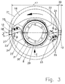
- the conveying effect of the larger mower disc (5, 8) with an elliptical basic shape can be increased in the area of the larger longitudinal extension (17), for example by arranging notches (22) in the direction of rotation (FIG. 3).
- the outer mower discs (4,5; 8,9) of the disc mower are equipped with additional drum-like conveying elements (29) according to the exemplary embodiment, (Fig. 3; 4), which support the promotion above the cutting plane of the cutting knife (10) and the mower disc.
- drum-like conveying members (29) On these drum-like conveying members (29), further conveying members (30, 31) of different shapes are arranged distributed over the circumference. They also help to promote the crop, especially in the upper area of the mowing swath that forms.
- a transfer device (32, 33) is provided according to the invention, the effective part of which preferably consists of flexible material.
Landscapes
- Life Sciences & Earth Sciences (AREA)
- Environmental Sciences (AREA)
- Harvester Elements (AREA)
- Agricultural Chemicals And Associated Chemicals (AREA)
Applications Claiming Priority (2)
| Application Number | Priority Date | Filing Date | Title |
|---|---|---|---|
| DE29517559U | 1995-11-06 | ||
| DE29517559U DE29517559U1 (de) | 1995-11-06 | 1995-11-06 | Scheibenmähwerk |
Publications (2)
| Publication Number | Publication Date |
|---|---|
| EP0771521A1 true EP0771521A1 (fr) | 1997-05-07 |
| EP0771521B1 EP0771521B1 (fr) | 2001-05-30 |
Family
ID=8015058
Family Applications (1)
| Application Number | Title | Priority Date | Filing Date |
|---|---|---|---|
| EP96116650A Expired - Lifetime EP0771521B1 (fr) | 1995-11-06 | 1996-10-17 | Barre de coupe à disque |
Country Status (6)
| Country | Link |
|---|---|
| US (1) | US5884461A (fr) |
| EP (1) | EP0771521B1 (fr) |
| AT (1) | ATE201553T1 (fr) |
| CZ (1) | CZ326296A3 (fr) |
| DE (2) | DE29517559U1 (fr) |
| HU (1) | HUP9602533A3 (fr) |
Cited By (2)
| Publication number | Priority date | Publication date | Assignee | Title |
|---|---|---|---|---|
| EP0891693A1 (fr) * | 1997-07-18 | 1999-01-20 | Deere & Company | Barre de coupe à disque et dispositif de coupe |
| CN108605493A (zh) * | 2018-06-21 | 2018-10-02 | 芜湖易泽中小企业公共服务股份有限公司 | 一种基于物联网的割草机器人 |
Families Citing this family (8)
| Publication number | Priority date | Publication date | Assignee | Title |
|---|---|---|---|---|
| AUPO359796A0 (en) * | 1996-11-12 | 1996-12-05 | Bird, Ronald George | Cutter apparatus |
| GB9721311D0 (en) * | 1997-10-09 | 1997-12-10 | Kverneland Taarup As | Multi-disc mowing machine |
| FR2772551B1 (fr) * | 1997-12-19 | 2000-02-11 | Kuhn Sa | Dispositif elevateur de fourrage destine a equiper un element de coupe rotatif de faucheuse |
| US6311463B1 (en) * | 2000-03-14 | 2001-11-06 | Deere & Company | Rotary mower cutter disc having self-cleaning knife mount shield |
| DE10018391A1 (de) * | 2000-04-13 | 2001-10-25 | Krone Bernard Maschf Gmbh | Mähmaschine |
| US7647758B1 (en) | 2008-10-30 | 2010-01-19 | Cnh America Llc | Device for reducing debris accumulation in a rotary cutterhead |
| DE102015206845B4 (de) * | 2015-04-16 | 2024-08-22 | Maschinenfabrik Kemper Gmbh & Co. Kg | Schneidwerk zur Ganzpflanzenernte |
| US20250024778A1 (en) * | 2023-07-20 | 2025-01-23 | Firefly Automatix, Inc. | Mower cutting unit having blades and lifting devices |
Citations (11)
| Publication number | Priority date | Publication date | Assignee | Title |
|---|---|---|---|---|
| DE2222415A1 (de) * | 1972-05-06 | 1973-11-15 | Hans Grenzebach | Aussenabteiler fuer rotationsmaehwerke |
| FR2297552A1 (fr) * | 1975-01-16 | 1976-08-13 | Fahr Ag Maschf | Faucheuse rotative |
| DE2524348A1 (de) * | 1975-06-02 | 1976-12-16 | Niemeyer Soehne H | Maehmaschine |
| FR2326857A1 (fr) * | 1975-10-10 | 1977-05-06 | Multinorm Bv | Dispositif de coupe perfectionne pour faucheuse |
| DE2703043A1 (de) * | 1977-01-26 | 1978-07-27 | Krone Bernhard Gmbh Maschf | Maehmaschine fuer den seitlichen anbau an einen schlepper |
| FR2380713A1 (fr) * | 1977-02-17 | 1978-09-15 | Texas Industries Inc | Faucheuse |
| DE3324851A1 (de) * | 1983-07-09 | 1985-01-17 | H. Niemeyer Söhne GmbH & Co KG, 4446 Hörstel | Maehmaschine |
| EP0188682A1 (fr) * | 1985-01-15 | 1986-07-30 | GREENLAND GMBH & CO. KG | Faucheuse rotative |
| NL8601559A (nl) * | 1986-06-17 | 1988-01-18 | Bernardus Petrus Antonius Zwee | Maaimachine. |
| EP0358045A1 (fr) * | 1988-09-05 | 1990-03-14 | H. Niemeyer Söhne GmbH & Co. KG | Faucheuse |
| DE4401500C1 (de) * | 1994-01-20 | 1995-01-19 | Moertl Schleppergeraetebau | An einem Schlepper ansetzbares Tellermähwerk |
Family Cites Families (9)
| Publication number | Priority date | Publication date | Assignee | Title |
|---|---|---|---|---|
| US2625784A (en) * | 1948-10-22 | 1953-01-20 | Cadwallader W Kelsey | Multiple windrowing disk type mower |
| NL7513926A (nl) * | 1975-11-28 | 1977-06-01 | Multinorm Bv | Maaiinrichting. |
| FR2377755A1 (fr) * | 1977-01-19 | 1978-08-18 | Vicon Nv | Faucheuse, tondeuse a gazon ou machine analogue |
| EP0200855A1 (fr) * | 1980-08-14 | 1986-11-12 | National Research Development Corporation | Moissonneuse et procédés de mise en oeuvre |
| NL8302556A (nl) * | 1983-07-16 | 1985-02-18 | Zweegers P | Maaimachine. |
| DE3341041A1 (de) * | 1983-11-12 | 1985-05-23 | Maschinenfabrik Bermatingen GmbH & Co, 7775 Bermatingen | Landwirtschaftliche bodenbearbeitungsmaschine |
| US4531349A (en) * | 1984-03-23 | 1985-07-30 | Sperry Corporation | Rotary cutter for disc mower-conditioner |
| US5463852A (en) * | 1994-04-28 | 1995-11-07 | Hay & Forage Industries | Wide cut harvester having rotary cutter bed |
| US5600943A (en) * | 1995-09-29 | 1997-02-11 | Ryan; Cyril A. | High brush mower |
-
1995
- 1995-11-06 DE DE29517559U patent/DE29517559U1/de not_active Expired - Lifetime
-
1996
- 1996-09-16 HU HU9602533A patent/HUP9602533A3/hu unknown
- 1996-10-03 US US08/723,629 patent/US5884461A/en not_active Expired - Fee Related
- 1996-10-17 AT AT96116650T patent/ATE201553T1/de not_active IP Right Cessation
- 1996-10-17 EP EP96116650A patent/EP0771521B1/fr not_active Expired - Lifetime
- 1996-10-17 DE DE59606993T patent/DE59606993D1/de not_active Expired - Fee Related
- 1996-11-06 CZ CZ963262A patent/CZ326296A3/cs unknown
Patent Citations (11)
| Publication number | Priority date | Publication date | Assignee | Title |
|---|---|---|---|---|
| DE2222415A1 (de) * | 1972-05-06 | 1973-11-15 | Hans Grenzebach | Aussenabteiler fuer rotationsmaehwerke |
| FR2297552A1 (fr) * | 1975-01-16 | 1976-08-13 | Fahr Ag Maschf | Faucheuse rotative |
| DE2524348A1 (de) * | 1975-06-02 | 1976-12-16 | Niemeyer Soehne H | Maehmaschine |
| FR2326857A1 (fr) * | 1975-10-10 | 1977-05-06 | Multinorm Bv | Dispositif de coupe perfectionne pour faucheuse |
| DE2703043A1 (de) * | 1977-01-26 | 1978-07-27 | Krone Bernhard Gmbh Maschf | Maehmaschine fuer den seitlichen anbau an einen schlepper |
| FR2380713A1 (fr) * | 1977-02-17 | 1978-09-15 | Texas Industries Inc | Faucheuse |
| DE3324851A1 (de) * | 1983-07-09 | 1985-01-17 | H. Niemeyer Söhne GmbH & Co KG, 4446 Hörstel | Maehmaschine |
| EP0188682A1 (fr) * | 1985-01-15 | 1986-07-30 | GREENLAND GMBH & CO. KG | Faucheuse rotative |
| NL8601559A (nl) * | 1986-06-17 | 1988-01-18 | Bernardus Petrus Antonius Zwee | Maaimachine. |
| EP0358045A1 (fr) * | 1988-09-05 | 1990-03-14 | H. Niemeyer Söhne GmbH & Co. KG | Faucheuse |
| DE4401500C1 (de) * | 1994-01-20 | 1995-01-19 | Moertl Schleppergeraetebau | An einem Schlepper ansetzbares Tellermähwerk |
Cited By (2)
| Publication number | Priority date | Publication date | Assignee | Title |
|---|---|---|---|---|
| EP0891693A1 (fr) * | 1997-07-18 | 1999-01-20 | Deere & Company | Barre de coupe à disque et dispositif de coupe |
| CN108605493A (zh) * | 2018-06-21 | 2018-10-02 | 芜湖易泽中小企业公共服务股份有限公司 | 一种基于物联网的割草机器人 |
Also Published As
| Publication number | Publication date |
|---|---|
| CZ326296A3 (en) | 1997-05-14 |
| US5884461A (en) | 1999-03-23 |
| HUP9602533A3 (en) | 1998-06-29 |
| HU9602533D0 (en) | 1996-11-28 |
| EP0771521B1 (fr) | 2001-05-30 |
| ATE201553T1 (de) | 2001-06-15 |
| DE29517559U1 (de) | 1996-01-25 |
| DE59606993D1 (de) | 2001-07-05 |
| HUP9602533A2 (en) | 1997-08-28 |
Similar Documents
| Publication | Publication Date | Title |
|---|---|---|
| DE19748475C2 (de) | Mähwerk für Rasenmäher | |
| EP0891693B1 (fr) | Barre de coupe à disque et dispositif de coupe | |
| EP1010363B1 (fr) | Machine pour faucher et hacher le mais et les plantes à tiges similaires | |
| DE102004022534B4 (de) | Erntemaschine zum Ernten von stängelartigem Erntegut wie Mais oder dergleichen | |
| DE69511310T2 (de) | Siebausbildung für Mähdrescher | |
| DE1782826A1 (de) | Freischneidendes maehwerk (anordnung eines schwadbildners) | |
| DE3874305T2 (de) | Maehwerk mit versteiftem maehbalken. | |
| DE3017856C2 (fr) | ||
| EP0771521B1 (fr) | Barre de coupe à disque | |
| AT389976B (de) | Foerder- und schneideinrichtung fuer einen ladewagen | |
| EP0097943A1 (fr) | Faucheuse | |
| DE2110622A1 (de) | Kreiselmaeher | |
| CH648987A5 (de) | Erntemaschine zum schwadlegen oder schwadwenden oder zum zett-wenden von schnittgut, insbesondere gras oder heu. | |
| DE2749046B2 (de) | Verteilereinrichtung für Häcksler | |
| DE102020002342A1 (de) | Mulchgerät | |
| DE8014119U1 (de) | Verteileinrichtung für Häcksler | |
| DE2844235A1 (de) | Heuwerbungsmaschine | |
| DE10157289A1 (de) | Mähwerk mit wenigstens zwei gekoppelten Mähbalken | |
| DE2345494A1 (de) | Sammelblech-anordnung bei einem kolbenpflueck-vorsatzgeraet | |
| DE2915245C2 (de) | Mähbalken | |
| EP0664075B1 (fr) | Faucheuse à disques accouplée à un tracteur | |
| DE202017101979U1 (de) | Landwirtschaftliches Bodenbearbeitungsgerät | |
| DE2452659A1 (de) | Schneidevorrichtung fuer pflanzen | |
| DE1582292B2 (de) | Mähmaschine | |
| CH619109A5 (en) | Front-mounted mower for mounting on a drive vehicle |
Legal Events
| Date | Code | Title | Description |
|---|---|---|---|
| PUAI | Public reference made under article 153(3) epc to a published international application that has entered the european phase |
Free format text: ORIGINAL CODE: 0009012 |
|
| AK | Designated contracting states |
Kind code of ref document: A1 Designated state(s): AT CH DE DK ES FR GB IT LI NL |
|
| 17P | Request for examination filed |
Effective date: 19970721 |
|
| RAP1 | Party data changed (applicant data changed or rights of an application transferred) |
Owner name: NIEMEYER LANDMASCHINEN GMBH |
|
| 17Q | First examination report despatched |
Effective date: 19990722 |
|
| GRAG | Despatch of communication of intention to grant |
Free format text: ORIGINAL CODE: EPIDOS AGRA |
|
| GRAG | Despatch of communication of intention to grant |
Free format text: ORIGINAL CODE: EPIDOS AGRA |
|
| GRAH | Despatch of communication of intention to grant a patent |
Free format text: ORIGINAL CODE: EPIDOS IGRA |
|
| GRAH | Despatch of communication of intention to grant a patent |
Free format text: ORIGINAL CODE: EPIDOS IGRA |
|
| GRAA | (expected) grant |
Free format text: ORIGINAL CODE: 0009210 |
|
| AK | Designated contracting states |
Kind code of ref document: B1 Designated state(s): AT CH DE DK ES FR GB IT LI NL |
|
| PG25 | Lapsed in a contracting state [announced via postgrant information from national office to epo] |
Ref country code: NL Free format text: LAPSE BECAUSE OF FAILURE TO SUBMIT A TRANSLATION OF THE DESCRIPTION OR TO PAY THE FEE WITHIN THE PRESCRIBED TIME-LIMIT Effective date: 20010530 Ref country code: IT Free format text: LAPSE BECAUSE OF FAILURE TO SUBMIT A TRANSLATION OF THE DESCRIPTION OR TO PAY THE FEE WITHIN THE PRESCRIBED TIME-LIMIT;WARNING: LAPSES OF ITALIAN PATENTS WITH EFFECTIVE DATE BEFORE 2007 MAY HAVE OCCURRED AT ANY TIME BEFORE 2007. THE CORRECT EFFECTIVE DATE MAY BE DIFFERENT FROM THE ONE RECORDED. Effective date: 20010530 Ref country code: GB Free format text: LAPSE BECAUSE OF FAILURE TO SUBMIT A TRANSLATION OF THE DESCRIPTION OR TO PAY THE FEE WITHIN THE PRESCRIBED TIME-LIMIT Effective date: 20010530 |
|
| REF | Corresponds to: |
Ref document number: 201553 Country of ref document: AT Date of ref document: 20010615 Kind code of ref document: T |
|
| REG | Reference to a national code |
Ref country code: CH Ref legal event code: EP |
|
| REF | Corresponds to: |
Ref document number: 59606993 Country of ref document: DE Date of ref document: 20010705 |
|
| PG25 | Lapsed in a contracting state [announced via postgrant information from national office to epo] |
Ref country code: DK Free format text: LAPSE BECAUSE OF FAILURE TO SUBMIT A TRANSLATION OF THE DESCRIPTION OR TO PAY THE FEE WITHIN THE PRESCRIBED TIME-LIMIT Effective date: 20010830 |
|
| PG25 | Lapsed in a contracting state [announced via postgrant information from national office to epo] |
Ref country code: AT Free format text: LAPSE BECAUSE OF NON-PAYMENT OF DUE FEES Effective date: 20011017 |
|
| PG25 | Lapsed in a contracting state [announced via postgrant information from national office to epo] |
Ref country code: LI Free format text: LAPSE BECAUSE OF NON-PAYMENT OF DUE FEES Effective date: 20011031 Ref country code: CH Free format text: LAPSE BECAUSE OF NON-PAYMENT OF DUE FEES Effective date: 20011031 |
|
| NLV1 | Nl: lapsed or annulled due to failure to fulfill the requirements of art. 29p and 29m of the patents act | ||
| GBV | Gb: ep patent (uk) treated as always having been void in accordance with gb section 77(7)/1977 [no translation filed] |
Effective date: 20010530 |
|
| PG25 | Lapsed in a contracting state [announced via postgrant information from national office to epo] |
Ref country code: ES Free format text: LAPSE BECAUSE OF FAILURE TO SUBMIT A TRANSLATION OF THE DESCRIPTION OR TO PAY THE FEE WITHIN THE PRESCRIBED TIME-LIMIT Effective date: 20011130 |
|
| EN | Fr: translation not filed | ||
| PLBE | No opposition filed within time limit |
Free format text: ORIGINAL CODE: 0009261 |
|
| STAA | Information on the status of an ep patent application or granted ep patent |
Free format text: STATUS: NO OPPOSITION FILED WITHIN TIME LIMIT |
|
| REG | Reference to a national code |
Ref country code: FR Ref legal event code: RN |
|
| 26N | No opposition filed | ||
| REG | Reference to a national code |
Ref country code: CH Ref legal event code: PL |
|
| PG25 | Lapsed in a contracting state [announced via postgrant information from national office to epo] |
Ref country code: DE Free format text: LAPSE BECAUSE OF NON-PAYMENT OF DUE FEES Effective date: 20020702 |
|
| ET | Fr: translation filed | ||
| REG | Reference to a national code |
Ref country code: FR Ref legal event code: FC |
|
| PGFP | Annual fee paid to national office [announced via postgrant information from national office to epo] |
Ref country code: FR Payment date: 20031030 Year of fee payment: 8 |
|
| PG25 | Lapsed in a contracting state [announced via postgrant information from national office to epo] |
Ref country code: FR Free format text: LAPSE BECAUSE OF NON-PAYMENT OF DUE FEES Effective date: 20050630 |
|
| REG | Reference to a national code |
Ref country code: FR Ref legal event code: ST |