EP0771643A2 - Procédé et table de transfert pour transporter en continu une matière plastique en forme de ruban. - Google Patents
Procédé et table de transfert pour transporter en continu une matière plastique en forme de ruban. Download PDFInfo
- Publication number
- EP0771643A2 EP0771643A2 EP96117461A EP96117461A EP0771643A2 EP 0771643 A2 EP0771643 A2 EP 0771643A2 EP 96117461 A EP96117461 A EP 96117461A EP 96117461 A EP96117461 A EP 96117461A EP 0771643 A2 EP0771643 A2 EP 0771643A2
- Authority
- EP
- European Patent Office
- Prior art keywords
- conveying
- conveying direction
- rubber
- band
- belt
- Prior art date
- Legal status (The legal status is an assumption and is not a legal conclusion. Google has not performed a legal analysis and makes no representation as to the accuracy of the status listed.)
- Granted
Links
- 239000000463 material Substances 0.000 title claims abstract description 31
- 239000004033 plastic Substances 0.000 title claims abstract description 20
- 238000000034 method Methods 0.000 title claims abstract description 11
- 238000004519 manufacturing process Methods 0.000 claims description 7
- 230000032258 transport Effects 0.000 abstract 1
- 238000003860 storage Methods 0.000 description 9
- 230000015572 biosynthetic process Effects 0.000 description 5
- 238000006073 displacement reaction Methods 0.000 description 4
- 239000004744 fabric Substances 0.000 description 4
- 238000011144 upstream manufacturing Methods 0.000 description 3
- 238000004804 winding Methods 0.000 description 3
- 238000006243 chemical reaction Methods 0.000 description 2
- 230000001788 irregular Effects 0.000 description 2
- 238000003825 pressing Methods 0.000 description 2
- 238000010276 construction Methods 0.000 description 1
- 238000005520 cutting process Methods 0.000 description 1
- 238000011143 downstream manufacturing Methods 0.000 description 1
- 230000000977 initiatory effect Effects 0.000 description 1
- 238000005259 measurement Methods 0.000 description 1
- 230000007935 neutral effect Effects 0.000 description 1
- 238000005457 optimization Methods 0.000 description 1
- 230000001105 regulatory effect Effects 0.000 description 1
Images


Classifications
-
- B—PERFORMING OPERATIONS; TRANSPORTING
- B29—WORKING OF PLASTICS; WORKING OF SUBSTANCES IN A PLASTIC STATE IN GENERAL
- B29D—PRODUCING PARTICULAR ARTICLES FROM PLASTICS OR FROM SUBSTANCES IN A PLASTIC STATE
- B29D30/00—Producing pneumatic or solid tyres or parts thereof
- B29D30/06—Pneumatic tyres or parts thereof (e.g. produced by casting, moulding, compression moulding, injection moulding, centrifugal casting)
- B29D30/38—Textile inserts, e.g. cord or canvas layers, for tyres; Treatment of inserts prior to building the tyre
- B29D30/44—Stretching or treating the layers before application on the drum
-
- B—PERFORMING OPERATIONS; TRANSPORTING
- B65—CONVEYING; PACKING; STORING; HANDLING THIN OR FILAMENTARY MATERIAL
- B65H—HANDLING THIN OR FILAMENTARY MATERIAL, e.g. SHEETS, WEBS, CABLES
- B65H23/00—Registering, tensioning, smoothing or guiding webs
- B65H23/02—Registering, tensioning, smoothing or guiding webs transversely
- B65H23/032—Controlling transverse register of web
- B65H23/038—Controlling transverse register of web by rollers
-
- B—PERFORMING OPERATIONS; TRANSPORTING
- B29—WORKING OF PLASTICS; WORKING OF SUBSTANCES IN A PLASTIC STATE IN GENERAL
- B29D—PRODUCING PARTICULAR ARTICLES FROM PLASTICS OR FROM SUBSTANCES IN A PLASTIC STATE
- B29D30/00—Producing pneumatic or solid tyres or parts thereof
- B29D30/06—Pneumatic tyres or parts thereof (e.g. produced by casting, moulding, compression moulding, injection moulding, centrifugal casting)
- B29D30/38—Textile inserts, e.g. cord or canvas layers, for tyres; Treatment of inserts prior to building the tyre
- B29D30/44—Stretching or treating the layers before application on the drum
- B29D2030/4406—Adjusting the positions of the layers
-
- B—PERFORMING OPERATIONS; TRANSPORTING
- B29—WORKING OF PLASTICS; WORKING OF SUBSTANCES IN A PLASTIC STATE IN GENERAL
- B29D—PRODUCING PARTICULAR ARTICLES FROM PLASTICS OR FROM SUBSTANCES IN A PLASTIC STATE
- B29D30/00—Producing pneumatic or solid tyres or parts thereof
- B29D30/06—Pneumatic tyres or parts thereof (e.g. produced by casting, moulding, compression moulding, injection moulding, centrifugal casting)
- B29D30/38—Textile inserts, e.g. cord or canvas layers, for tyres; Treatment of inserts prior to building the tyre
- B29D30/44—Stretching or treating the layers before application on the drum
- B29D2030/4437—Adjusting the dimensions of the layers
-
- B—PERFORMING OPERATIONS; TRANSPORTING
- B29—WORKING OF PLASTICS; WORKING OF SUBSTANCES IN A PLASTIC STATE IN GENERAL
- B29D—PRODUCING PARTICULAR ARTICLES FROM PLASTICS OR FROM SUBSTANCES IN A PLASTIC STATE
- B29D30/00—Producing pneumatic or solid tyres or parts thereof
- B29D30/06—Pneumatic tyres or parts thereof (e.g. produced by casting, moulding, compression moulding, injection moulding, centrifugal casting)
- B29D30/38—Textile inserts, e.g. cord or canvas layers, for tyres; Treatment of inserts prior to building the tyre
- B29D30/44—Stretching or treating the layers before application on the drum
- B29D2030/4437—Adjusting the dimensions of the layers
- B29D2030/4443—Increasing the length of the layers, e.g. by stretching
-
- B—PERFORMING OPERATIONS; TRANSPORTING
- B29—WORKING OF PLASTICS; WORKING OF SUBSTANCES IN A PLASTIC STATE IN GENERAL
- B29D—PRODUCING PARTICULAR ARTICLES FROM PLASTICS OR FROM SUBSTANCES IN A PLASTIC STATE
- B29D30/00—Producing pneumatic or solid tyres or parts thereof
- B29D30/06—Pneumatic tyres or parts thereof (e.g. produced by casting, moulding, compression moulding, injection moulding, centrifugal casting)
- B29D30/38—Textile inserts, e.g. cord or canvas layers, for tyres; Treatment of inserts prior to building the tyre
- B29D30/44—Stretching or treating the layers before application on the drum
- B29D2030/4437—Adjusting the dimensions of the layers
- B29D2030/445—Shortening the layers, e.g. by acting on the lateral edges or on the thickness or by cutting
-
- B—PERFORMING OPERATIONS; TRANSPORTING
- B29—WORKING OF PLASTICS; WORKING OF SUBSTANCES IN A PLASTIC STATE IN GENERAL
- B29D—PRODUCING PARTICULAR ARTICLES FROM PLASTICS OR FROM SUBSTANCES IN A PLASTIC STATE
- B29D30/00—Producing pneumatic or solid tyres or parts thereof
- B29D30/06—Pneumatic tyres or parts thereof (e.g. produced by casting, moulding, compression moulding, injection moulding, centrifugal casting)
- B29D30/38—Textile inserts, e.g. cord or canvas layers, for tyres; Treatment of inserts prior to building the tyre
- B29D30/44—Stretching or treating the layers before application on the drum
- B29D2030/4468—Holding the layers
-
- B—PERFORMING OPERATIONS; TRANSPORTING
- B29—WORKING OF PLASTICS; WORKING OF SUBSTANCES IN A PLASTIC STATE IN GENERAL
- B29D—PRODUCING PARTICULAR ARTICLES FROM PLASTICS OR FROM SUBSTANCES IN A PLASTIC STATE
- B29D30/00—Producing pneumatic or solid tyres or parts thereof
- B29D30/06—Pneumatic tyres or parts thereof (e.g. produced by casting, moulding, compression moulding, injection moulding, centrifugal casting)
- B29D30/38—Textile inserts, e.g. cord or canvas layers, for tyres; Treatment of inserts prior to building the tyre
- B29D30/44—Stretching or treating the layers before application on the drum
- B29D2030/4468—Holding the layers
- B29D2030/4487—Holding the layers by using mechanical means, e.g. grippers or pressing bars
-
- B—PERFORMING OPERATIONS; TRANSPORTING
- B65—CONVEYING; PACKING; STORING; HANDLING THIN OR FILAMENTARY MATERIAL
- B65H—HANDLING THIN OR FILAMENTARY MATERIAL, e.g. SHEETS, WEBS, CABLES
- B65H2801/00—Application field
- B65H2801/93—Tyres
Definitions
- the invention relates to a method for conveying a band made of plastic material, in particular a rubber band, to a further processing device and a conveyor table for continuously conveying band-shaped plastic material, in particular rubber material, preferably for producing a tire.
- the individual rubber strips must be placed over the entire circumference of the building drum as precisely as possible in the same axial position. Fluctuations in the axial position, in particular in the connection area between the tread and the side strip, lead to uneven tire properties over the circumference of the tire. For the production, it is therefore known that tire builders pull the strips manually to compensate for fluctuations in the edge line laterally to compensate for the curvilinearity to the right or to the left when manually placing the cut strips on the building drum.
- the invention is based on the object of improving the accuracy in the feeding of a continuously conveyed plastic band material, in particular a rubber band, preferably for tire manufacture, and thus the further processability in a downstream processing device with simple means.
- the object is achieved by the method for conveying a band of plastic material, in particular a rubber band, to a further processing device according to the features of claim 1 and by the formation of a conveyor table for the continuous conveyance of band-shaped plastic material, in particular rubber material, preferably for producing a tire , solved to a further processing device according to the features of claim 5.
- a conveyor table for the continuous conveying of belt-shaped plastic material to a further processing device with a straightening device for straightening a lateral boundary edge of the belt and with a constant conveying direction in the area of the straightening device is made possible by the means for changing the lateral position of the successively trained in the conveying direction perpendicular to the conveying direction Cross-sectional areas of the belt to each other and to align these cross-sectional areas with their one side delimiting the belt in a line parallel to the conveying direction in an adjustable lateral position of the width of the conveyor table, an exact setting of a side delimiting the continuously conveyed band-shaped plastic material in a line parallel to the conveying direction in according to the individual requirements of the further processing device adjustable lateral position in de r Width of the conveyor table.
- the belt made of plastic material can be fed to the further processing device in a precisely defined, constant position across the width of the conveyor table without a great deal of control and regulation work for changing the conveying direction. Elaborate controls and regulation can be
- the processing quality is thus improved by simple means by deforming the rubber band in a straightening device upstream of the processing device in the conveying direction.
- a method is preferred in which, in the straightening device, the rotating body of the rubber band aligned obliquely to the conveying direction presses laterally against the alignment elements of the straightening device while deforming the rubber band in its conveying plane.
- the inclined rotating bodies ensure safe conveying by the straightening device in the conveying direction as well as a lateral displacement of the belt towards the alignment element, against which they press the belt and, due to the continuous conveying, deform it into a straight edge.
- a deflection of the belt with from the belt side, which faces the side alignment elements, to the opposite side of the continuous increase maximum deflection of the belt from the conveyor level and a subsequent re-deflection.
- the continuously changing deflection causes the web to be continuously shifted sideways to the side with the smaller maximum deflection against the lateral alignment elements.
- the cross-sectional areas of the rubber belt arranged one behind the other in the conveying direction and perpendicular to the conveying direction are laterally displaced relative to one another and, with their side pointing towards the lateral alignment element, aligned on a straight line parallel to the conveying direction.
- the ideal measure for the lateral force pressing the plastic band against the alignment elements can be set by suitably adjusting the angle ⁇ of the rotating body.
- the axis of rotation can be formed both at an angle ⁇ to the conveying direction and at an angle ⁇ to the conveying plane in a plane transverse to the conveying direction.
- the rationing body can be freely rotatable, so that the deflection takes place solely on the basis of the conveying speed transmitted by the conveying means to the conveyor belt and the frictional forces acting between the conveyor belt and the freely rotating rotating body.
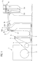
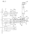
- FIGS. 1 and 2 show the schematic structure of the conveying path of continuously conveyed rubber belts for producing tire side walls from a belt store 1 of a known type to a tire building drum 42 of a known type. Since two essentially identical tire sidewalls are produced in parallel for the production of the vehicle tire, two rubber bands 4 (l), 4 (r) are also conveyed in parallel from the band store 1 to the tire building drum for producing a left and a right tire sidewall. Since the conveying device for both rubber belts 4 (l), 4 (r) are identical and mirrored to the center line between the two conveying paths, the conveying is described below using the example of the right rubber belt 4 (r) designated with the index r.
- the tape store 1 is designed in a known manner with a winding mandrel 3 and with an unwind drum 2. From the unwinding drum 2, the rubber material placed on the separating circulating fabric material of known design is unwound with the fabric material and guided around a deflection roller 5. The separating fabric material is deflected downward behind the deflecting roller 5 and wound up on the winding drum.
- the rubber band 4 is separated from the fabric material in a known manner and is introduced around the deflection roller 6 via a storage loop 7 and around conveyor tables 8 and 10 designed with deflection rollers into a further storage loop 13 with a 90 ° change of direction, from where the rubber band 4 after the change of direction is guided vertically upwards over a conveyor table 19 through a straightening device 16 and is pulled around deflection rollers 14 and over a driven conveyor belt 35 to the building drum 42. If there is sufficient space structurally, the 90 ° change of direction can be omitted.
- axes 20 and 21 are formed in the conveyor table 19 with axes 20 and 21 arranged one behind the other in the conveying direction and on which deflection rollers 22, which are evenly spaced over the width of the conveyor table, are rotatably supported independently of one another.
- the rubber belt 4 is guided by the conveyor belt 35, which is guided around rotatably mounted deflecting rollers, of which only the deflecting roller 36 is shown in FIG. 4, and which is in drive connection with a controllable drive device, via the deflecting rollers 22 and across one across the conveying direction Aligned deflection axis 14 drawn equidistantly from one another and, independently of one another, rotatably mounted rollers 34 distributed over the width of the conveyor table.
- the tangential plane to the deflecting rollers 22 of the axes 20 and 21 and, downstream in the conveying direction, the tangential plane to the deflecting rollers 22 of the axis 21 and to the deflecting rollers 34 of the axis 14 form between the axes 20 and axis 14 the conveyor plane 26 shown in broken lines.
- an axis 23 extending transversely to the conveying direction over the entire conveying table is mounted in the side wall 18 and in a bearing block 38.
- an axis 24 extending transversely to the conveying direction over the entire conveying straightening table is mounted in the side wall 18 and in a bearing block 39 between the axis 21 and the axis 14.
- the axes 23 and 24 each enclose an angle ⁇ and ⁇ 'to the conveying direction.
- the axes 23 and 24 enclose an angle ⁇ or ⁇ 'to the conveying plane in a plane which is perpendicular to the conveying plane.
- the angles ⁇ and ⁇ 'of the axes 23, 24, measured from the conveying direction with a view to the right in the conveying direction, are in each case less than 90 °, for example 84 °. Depending on the coefficients of friction between the rollers and the rubber belt, it is conceivable to limit the angular range to 82 ° to 86 ° to ensure safe conveying.
- the axes 23 and 24 are arranged so that their rollers 25 each extend with their outer diameters to the side of the conveying plane 26 on which the axes 20, 21 and 14 are located.
- the rubber belt is passed between the rollers 22 of the axes 20 and 21 and the rollers 34 of the deflection axis 14 on the one hand and the rollers 25 of the axes 23 and 24 on the other hand and through the rollers 25 out of their conveying plane and through the deflection rollers 22 and 34 back into them steered in.
- the rubber belt and the rollers 22, 25 and 34 are thereby under effective frictional contact.
- the inclined position of the axes 23 and 24 selected by the choice of the angle ⁇ or ⁇ 'cause a transverse displacement from the rollers 25 to the rubber belt 4 to the rotatable stop rollers 31, 32, 33.
- the rubber band is pressed with its edge 37 pointing to these stops 31, 32, 33 against the stops 31, 32, 33 and simultaneously funded in the funding direction.
- the edge 37 is aligned along the tangential plane of the stop rollers 31, 32, 33 parallel to the conveying direction by cross-sectional deformation of the rubber band 4.
- the rubber belt 4 is conveyed in the aligned state around the deflection rollers 34 via the conveyor belt 35 up to the building drum and is supplied to the latter in the aligned state.
- the deflecting rollers 34 which are designed to be rotatable independently of one another and parallel to one another and have a small axial width, the deflecting rollers 34 rotate in accordance with the thickness of the rubber material piled above them and the deflection radius formed thereby, so that the position of the stop edge 37 also adjusts to the neutral line of the rubber material not changed during the deflection around the axis 14 due to different thicknesses of the rubber material.
- the axes 23 and 24, as shown in FIG. 5, can be adjusted by an angle ⁇ or ⁇ 'according to the respective requirements with the aid of the adjusting shaft 40 and the bearing block 38, 39. are rotated out of a plane parallel to the conveying plane, so that the deflection rollers 25 closest to the stop bodies 31, 32, 33 are deflected the least and the rollers 25 which are furthest away from the stop bodies 31, 32, 33 are deflected the most.
- angles ⁇ , ⁇ 'adjustable It is also conceivable to make the angles ⁇ , ⁇ 'adjustable. It is also conceivable to design the actuating axes 23, 24 with a preset angle ⁇ , ⁇ 'and to design only the angles ⁇ , ⁇ ' to be adjustable.
- the new rubber belt 4 is still pulled in the old position of the belt store 1 'through the storage loop 7' around deflection rollers 15 'onto a table top 109' on the conveyor table 8 '. It is conceivable to arrange a straightening device 41 upstream of the deflection rollers 15 in the conveying direction, as is shown schematically in FIGS. 1 and 2.
- the straightening device 41 has essentially the same structure as the straightening device 16 already described.
- the deflecting rollers 34 described for the straightening device 16 instead of the deflecting rollers 34 described for the straightening device 16, the deflecting rollers 15 are rotatably mounted equidistantly parallel to one another independently of one another.
- Such a straightening device 41 enables the rubber belt 4 to be conveyed at a constant position transversely to the conveying direction in the position 1 'of the belt store 1 via the table top 9' and a table plate 11 fixed in a stationary manner. In this state, the conveying is stopped and the rubber belt between the table top 109 'and table 11 cut off with a cut transversely to the conveying direction in its end face.
Landscapes
- Engineering & Computer Science (AREA)
- Textile Engineering (AREA)
- Mechanical Engineering (AREA)
- Tyre Moulding (AREA)
Applications Claiming Priority (2)
| Application Number | Priority Date | Filing Date | Title |
|---|---|---|---|
| DE19541095 | 1995-11-03 | ||
| DE19541095A DE19541095C2 (de) | 1995-11-03 | 1995-11-03 | Verfahren zur Förderung eines Bandes aus plastischem Material und Fördertisch zur kontinuierlichen Förderung von bandförmigem plastischem Material |
Publications (3)
| Publication Number | Publication Date |
|---|---|
| EP0771643A2 true EP0771643A2 (fr) | 1997-05-07 |
| EP0771643A3 EP0771643A3 (fr) | 1997-11-05 |
| EP0771643B1 EP0771643B1 (fr) | 2002-01-16 |
Family
ID=7776594
Family Applications (1)
| Application Number | Title | Priority Date | Filing Date |
|---|---|---|---|
| EP96117461A Expired - Lifetime EP0771643B1 (fr) | 1995-11-03 | 1996-10-31 | Procédé et table de transfert pour transporter en continu une matière plastique en forme de ruban |
Country Status (3)
| Country | Link |
|---|---|
| US (1) | US5775562A (fr) |
| EP (1) | EP0771643B1 (fr) |
| DE (2) | DE19541095C2 (fr) |
Cited By (6)
| Publication number | Priority date | Publication date | Assignee | Title |
|---|---|---|---|---|
| WO1998053983A1 (fr) * | 1997-05-30 | 1998-12-03 | Vmi Epe Holland B.V. | Dispositif destine a appliquer une bande de renforcement |
| WO2007015898A1 (fr) * | 2005-08-01 | 2007-02-08 | The Steelastic Company, Llc | Systeme d'alignement de bande dans une machine de fabrication de ceintures pour pneumatiques |
| WO2014155240A1 (fr) * | 2013-03-27 | 2014-10-02 | Pirelli Tyre S.P.A. | Procédé et appareil pour obtenir des pneus pour roues de véhicule |
| WO2015181740A1 (fr) * | 2014-05-30 | 2015-12-03 | Pirelli Tyre S.P.A. | Appareil pour déposer des paires d'éléments allongés sur un tambour de formage et procédé pour obtenir des pneumatiques pour des roues de véhicule |
| EP3056334A1 (fr) * | 2015-02-12 | 2016-08-17 | Karl Eugen Fischer GmbH | Dispositif de traitement d'une bande collante, en particulier une bande de textile ou d'acier |
| CN106715104A (zh) * | 2014-08-08 | 2017-05-24 | Vmi荷兰公司 | 用于三角填充胶条的拉伸装置和包括该拉伸装置的三角胶条搬运系统 |
Families Citing this family (6)
| Publication number | Priority date | Publication date | Assignee | Title |
|---|---|---|---|---|
| DE102006012972B4 (de) * | 2006-03-21 | 2008-02-28 | Texmag Gmbh Vertriebsgesellschaft Gmbh | Vorrichtung zur Regelung des seitlichen Versatzes von Materialbahnen |
| US20120312451A1 (en) * | 2010-02-22 | 2012-12-13 | Pirelli Tyre S.P.A. | Process and apparatus for unwinding an elongated element provided with two service fabrics in order to build tyres for vehicle wheels |
| IT1398613B1 (it) | 2010-03-16 | 2013-03-08 | C M C Srl | Dispositivo e metodo per l'alimentazione di strisce continue ad una stazione di recisione trasversale di tali strisce |
| CN105253688A (zh) * | 2015-07-20 | 2016-01-20 | 海宁市睿创机械科技有限公司 | 一种钢包供料架装置 |
| CN112297407B (zh) * | 2020-10-19 | 2022-07-22 | 青岛美德橡塑有限公司 | 一种适用于不同规格的汽车密封条裁切前摆直防弯折设备 |
| NL2037030B1 (en) * | 2024-02-15 | 2025-08-25 | Vmi Holland Bv | Pressing device, tire component servicer and method for applying pressure to a tire component during conveyance |
Family Cites Families (13)
| Publication number | Priority date | Publication date | Assignee | Title |
|---|---|---|---|---|
| DE1063110B (de) * | 1957-03-20 | 1959-08-13 | Phoenix Gummiwerke Ag | Vorrichtung zum Ausrichten von fortlaufenden Gewebebahnen |
| US3069056A (en) * | 1960-04-13 | 1962-12-18 | Ind Ovens Inc | Web guiding and edge stretching means |
| US3107036A (en) * | 1961-09-14 | 1963-10-15 | Ind Ovens Inc | Self-adjusting web guiding apparatus |
| US3243089A (en) * | 1963-01-18 | 1966-03-29 | Reynolds Metals Co | Sidewise alignment of a longitudinally moving strip and the like |
| US3171579A (en) * | 1963-08-22 | 1965-03-02 | Mount Hope Machinery Ltd | Sheet guiding and width control apparatus |
| US3373288A (en) * | 1965-08-26 | 1968-03-12 | Web Press Eng Inc | Photosensitive web shifting apparatus |
| US3343737A (en) * | 1965-10-22 | 1967-09-26 | Ind Ovens Inc | Web guiding and edge maintaining means |
| US3664561A (en) * | 1969-11-26 | 1972-05-23 | Fife Corp | Web guiding device |
| US4095731A (en) * | 1977-02-04 | 1978-06-20 | The Goodyear Tire & Rubber Company | Guiding narrow strip |
| NL8007098A (nl) * | 1980-12-30 | 1982-07-16 | Vmi Epe Holland | Centreermechanisme. |
| US4554713A (en) * | 1982-09-07 | 1985-11-26 | Ppg Industries, Inc. | Apparatus for differentially stretching, aligning and cutting sheet material |
| US4666073A (en) * | 1984-07-25 | 1987-05-19 | Dufour Kenneth S | Spring biased spool type valve controller for a pneumatic dual diaphragm control system |
| LU86033A1 (fr) * | 1985-08-02 | 1986-02-18 | Goodyear Tire & Rubber | Appareil en vue d'acheminer des elements a un tambour de confection de bandages pneumatiques |
-
1995
- 1995-11-03 DE DE19541095A patent/DE19541095C2/de not_active Expired - Fee Related
-
1996
- 1996-10-31 EP EP96117461A patent/EP0771643B1/fr not_active Expired - Lifetime
- 1996-10-31 DE DE59608589T patent/DE59608589D1/de not_active Expired - Lifetime
- 1996-11-01 US US08/743,116 patent/US5775562A/en not_active Expired - Lifetime
Non-Patent Citations (1)
| Title |
|---|
| None |
Cited By (9)
| Publication number | Priority date | Publication date | Assignee | Title |
|---|---|---|---|---|
| WO1998053983A1 (fr) * | 1997-05-30 | 1998-12-03 | Vmi Epe Holland B.V. | Dispositif destine a appliquer une bande de renforcement |
| WO2007015898A1 (fr) * | 2005-08-01 | 2007-02-08 | The Steelastic Company, Llc | Systeme d'alignement de bande dans une machine de fabrication de ceintures pour pneumatiques |
| WO2014155240A1 (fr) * | 2013-03-27 | 2014-10-02 | Pirelli Tyre S.P.A. | Procédé et appareil pour obtenir des pneus pour roues de véhicule |
| WO2015181740A1 (fr) * | 2014-05-30 | 2015-12-03 | Pirelli Tyre S.P.A. | Appareil pour déposer des paires d'éléments allongés sur un tambour de formage et procédé pour obtenir des pneumatiques pour des roues de véhicule |
| RU2687944C2 (ru) * | 2014-05-30 | 2019-05-16 | Пирелли Тайр С.П.А. | Установка для укладки пар удлиненных элементов на формовочный барабан и способ получения шин для колес транспортных средств |
| CN106715104A (zh) * | 2014-08-08 | 2017-05-24 | Vmi荷兰公司 | 用于三角填充胶条的拉伸装置和包括该拉伸装置的三角胶条搬运系统 |
| CN106715104B (zh) * | 2014-08-08 | 2019-01-18 | Vmi荷兰公司 | 用于三角填充胶条的拉伸装置和包括该拉伸装置的三角胶条搬运系统 |
| US10647076B2 (en) | 2014-08-08 | 2020-05-12 | Vmi Holland B.V. | Stretching device for an apex filler strip for tire beads and apex handling system comprising the stretching device |
| EP3056334A1 (fr) * | 2015-02-12 | 2016-08-17 | Karl Eugen Fischer GmbH | Dispositif de traitement d'une bande collante, en particulier une bande de textile ou d'acier |
Also Published As
| Publication number | Publication date |
|---|---|
| DE59608589D1 (de) | 2002-02-21 |
| EP0771643B1 (fr) | 2002-01-16 |
| DE19541095C2 (de) | 2000-05-18 |
| US5775562A (en) | 1998-07-07 |
| EP0771643A3 (fr) | 1997-11-05 |
| DE19541095A1 (de) | 1997-05-07 |
Similar Documents
| Publication | Publication Date | Title |
|---|---|---|
| DE19641509C2 (de) | Verfahren zum Transport eines Gürtelaufbaustreifens zum Aufbau eines Gürtels für einen Fahrzeugluftreifen | |
| DE69528224T2 (de) | Gerät und Verfahren zum berührungslosen aktiven Spannen von sich bewegendem bandförmigem Material | |
| EP0498962B1 (fr) | Procédé et dispositif pour réaliser une bobine | |
| EP2949609B1 (fr) | Dispositif d'assemblage | |
| EP2046566B1 (fr) | Dispositif d'alimentation | |
| EP0958867B1 (fr) | Dispositif d'enroulement d'une bande | |
| DE19541095C2 (de) | Verfahren zur Förderung eines Bandes aus plastischem Material und Fördertisch zur kontinuierlichen Förderung von bandförmigem plastischem Material | |
| EP1502883B1 (fr) | Dispositif de transport transversal de rames de papier | |
| DE3315495C2 (de) | Vorrichtung zum Lagern von Papierbogen o.dgl. | |
| EP1013183B1 (fr) | Appareil pour enrober une bande autour des articles en forme de tige | |
| EP0697989B1 (fr) | Dispositif permettant de transferer et d'empiler des feuilles | |
| DE69807755T2 (de) | Druckwarenwickler und wickelverfahren | |
| DE60312983T2 (de) | Herstellung einer reifenverstärkungsstruktur mit der volumenregelung der matrix | |
| DE3812685C2 (de) | Verzögerungs-Vorrichtung für Bogenlagen | |
| DE2547507C2 (de) | Verfahren und Vorrichtung zum Abziehen und Zuführen einer unvulkanisierten Kautschukbahn von einem Vorratswickel auf eine Reifenaufbautrommel | |
| DE4322114A1 (de) | Umlenkwalze | |
| DE19901959A1 (de) | Verfahren zur Herstellung einer Gürtelbandage eines Fahrzeugluftreifens und Vorrichtung zur Herstellung | |
| EP0308688B1 (fr) | Dispositif d'alimentation des feuilles autour d'une trajectoire curviligne | |
| DE3744107C2 (fr) | ||
| DE10060752B4 (de) | Vorrichtung zum fortlaufenden Falzen von flachem Material | |
| EP0208244B1 (fr) | Dispositif pour rogner des produits imprimés délivrés en chevauchement | |
| DE2815829A1 (de) | Vorrichtung zum gruppenweisen abteilen von geschuppt uebereinanderliegenden werkstuecken | |
| DE19654857A1 (de) | Vorrichtung zum Trennen und seitlichem Auslenken durch Längsschnitt erzeugten Metallstreifen | |
| EP0437231A2 (fr) | Cylindre de renvoi | |
| DE3881702T2 (de) | Dornkonstruktion. |
Legal Events
| Date | Code | Title | Description |
|---|---|---|---|
| PUAI | Public reference made under article 153(3) epc to a published international application that has entered the european phase |
Free format text: ORIGINAL CODE: 0009012 |
|
| AK | Designated contracting states |
Kind code of ref document: A2 Designated state(s): DE FR GB IT |
|
| PUAL | Search report despatched |
Free format text: ORIGINAL CODE: 0009013 |
|
| AK | Designated contracting states |
Kind code of ref document: A3 Designated state(s): DE FR GB IT |
|
| RHK1 | Main classification (correction) |
Ipc: B29D 30/44 |
|
| 17P | Request for examination filed |
Effective date: 19980506 |
|
| 17Q | First examination report despatched |
Effective date: 19990923 |
|
| GRAG | Despatch of communication of intention to grant |
Free format text: ORIGINAL CODE: EPIDOS AGRA |
|
| GRAG | Despatch of communication of intention to grant |
Free format text: ORIGINAL CODE: EPIDOS AGRA |
|
| GRAG | Despatch of communication of intention to grant |
Free format text: ORIGINAL CODE: EPIDOS AGRA |
|
| GRAH | Despatch of communication of intention to grant a patent |
Free format text: ORIGINAL CODE: EPIDOS IGRA |
|
| GRAH | Despatch of communication of intention to grant a patent |
Free format text: ORIGINAL CODE: EPIDOS IGRA |
|
| GRAA | (expected) grant |
Free format text: ORIGINAL CODE: 0009210 |
|
| REG | Reference to a national code |
Ref country code: GB Ref legal event code: IF02 |
|
| AK | Designated contracting states |
Kind code of ref document: B1 Designated state(s): DE FR GB IT |
|
| REF | Corresponds to: |
Ref document number: 59608589 Country of ref document: DE Date of ref document: 20020221 |
|
| GBT | Gb: translation of ep patent filed (gb section 77(6)(a)/1977) |
Effective date: 20020529 |
|
| ET | Fr: translation filed | ||
| PLBE | No opposition filed within time limit |
Free format text: ORIGINAL CODE: 0009261 |
|
| STAA | Information on the status of an ep patent application or granted ep patent |
Free format text: STATUS: NO OPPOSITION FILED WITHIN TIME LIMIT |
|
| 26N | No opposition filed | ||
| PGFP | Annual fee paid to national office [announced via postgrant information from national office to epo] |
Ref country code: GB Payment date: 20051024 Year of fee payment: 10 |
|
| GBPC | Gb: european patent ceased through non-payment of renewal fee |
Effective date: 20061031 |
|
| PG25 | Lapsed in a contracting state [announced via postgrant information from national office to epo] |
Ref country code: GB Free format text: LAPSE BECAUSE OF NON-PAYMENT OF DUE FEES Effective date: 20061031 |
|
| PGFP | Annual fee paid to national office [announced via postgrant information from national office to epo] |
Ref country code: FR Payment date: 20131022 Year of fee payment: 18 Ref country code: DE Payment date: 20131031 Year of fee payment: 18 |
|
| PGFP | Annual fee paid to national office [announced via postgrant information from national office to epo] |
Ref country code: IT Payment date: 20131028 Year of fee payment: 18 |
|
| REG | Reference to a national code |
Ref country code: DE Ref legal event code: R119 Ref document number: 59608589 Country of ref document: DE |
|
| PG25 | Lapsed in a contracting state [announced via postgrant information from national office to epo] |
Ref country code: DE Free format text: LAPSE BECAUSE OF NON-PAYMENT OF DUE FEES Effective date: 20150501 |
|
| REG | Reference to a national code |
Ref country code: FR Ref legal event code: ST Effective date: 20150630 |
|
| PG25 | Lapsed in a contracting state [announced via postgrant information from national office to epo] |
Ref country code: FR Free format text: LAPSE BECAUSE OF NON-PAYMENT OF DUE FEES Effective date: 20141031 Ref country code: IT Free format text: LAPSE BECAUSE OF NON-PAYMENT OF DUE FEES Effective date: 20141031 |