EP0771905A2 - Rouleau à réglage de la flexion pour une calandre ou similaire - Google Patents
Rouleau à réglage de la flexion pour une calandre ou similaire Download PDFInfo
- Publication number
- EP0771905A2 EP0771905A2 EP96116465A EP96116465A EP0771905A2 EP 0771905 A2 EP0771905 A2 EP 0771905A2 EP 96116465 A EP96116465 A EP 96116465A EP 96116465 A EP96116465 A EP 96116465A EP 0771905 A2 EP0771905 A2 EP 0771905A2
- Authority
- EP
- European Patent Office
- Prior art keywords
- pressure
- interior
- drain
- support elements
- carrier
- Prior art date
- Legal status (The legal status is an assumption and is not a legal conclusion. Google has not performed a legal analysis and makes no representation as to the accuracy of the status listed.)
- Granted
Links
- 230000004888 barrier function Effects 0.000 claims abstract description 6
- 230000002706 hydrostatic effect Effects 0.000 claims description 2
- 239000012530 fluid Substances 0.000 description 3
- 230000000903 blocking effect Effects 0.000 description 2
- 238000010276 construction Methods 0.000 description 2
- 230000002730 additional effect Effects 0.000 description 1
- 230000002349 favourable effect Effects 0.000 description 1
Images
Classifications
-
- F—MECHANICAL ENGINEERING; LIGHTING; HEATING; WEAPONS; BLASTING
- F16—ENGINEERING ELEMENTS AND UNITS; GENERAL MEASURES FOR PRODUCING AND MAINTAINING EFFECTIVE FUNCTIONING OF MACHINES OR INSTALLATIONS; THERMAL INSULATION IN GENERAL
- F16C—SHAFTS; FLEXIBLE SHAFTS; ELEMENTS OR CRANKSHAFT MECHANISMS; ROTARY BODIES OTHER THAN GEARING ELEMENTS; BEARINGS
- F16C13/00—Rolls, drums, discs, or the like; Bearings or mountings therefor
- F16C13/02—Bearings
- F16C13/022—Bearings supporting a hollow roll mantle rotating with respect to a yoke or axle
- F16C13/024—Bearings supporting a hollow roll mantle rotating with respect to a yoke or axle adjustable for positioning, e.g. radial movable bearings for controlling the deflection along the length of the roll mantle
- F16C13/026—Bearings supporting a hollow roll mantle rotating with respect to a yoke or axle adjustable for positioning, e.g. radial movable bearings for controlling the deflection along the length of the roll mantle by fluid pressure
- F16C13/028—Bearings supporting a hollow roll mantle rotating with respect to a yoke or axle adjustable for positioning, e.g. radial movable bearings for controlling the deflection along the length of the roll mantle by fluid pressure with a plurality of supports along the length of the roll mantle, e.g. hydraulic jacks
-
- D—TEXTILES; PAPER
- D21—PAPER-MAKING; PRODUCTION OF CELLULOSE
- D21G—CALENDERS; ACCESSORIES FOR PAPER-MAKING MACHINES
- D21G1/00—Calenders; Smoothing apparatus
- D21G1/02—Rolls; Their bearings
- D21G1/0206—Controlled deflection rolls
- D21G1/0213—Controlled deflection rolls with deflection compensation means acting between the roller shell and its supporting member
- D21G1/022—Controlled deflection rolls with deflection compensation means acting between the roller shell and its supporting member the means using fluid pressure
Definitions
- the invention relates to a deflection-controllable roll for a calender or the like, in which a roll shell is supported with the aid of hydrostatic support elements on a non-rotatably supported carrier passing through the roll shell and the support elements have at least one pocket in their support surface facing the inner surface of the shell and delimit a pressure space with a pressure surface facing the carrier, which is connected on the one hand to a pressure medium supply line and on the other hand to the pocket via a throttle, the support elements being designed as ring elements with an annular pocket and an annular pressure surface and the interior enclosed by the ring element having a Switch valve with only one closed position and one open position drain line in connection, according to DE 44 29 499 C1.
- roller shown in the parent patent allows a wide adjustment range of the supporting force and only requires one pressure medium supply line and one drain line per supporting element.
- a further simplification is to give the adjustable throttle element only two positions, namely a closed position and an open position. You can then use relatively simple switching valves.
- the invention has for its object to provide a particularly simple and reliable way of influencing the internal pressure of the support elements.
- the switching valve in the drain line is a check valve opening towards the drain side, the drain side of which can be acted upon either with an opening pressure below the interior pressure or with a barrier pressure above the interior pressure.
- the switching valve is therefore controlled purely hydraulically. If there is opening pressure on the outlet side, hydraulic fluid can flow out of the interior and the interior pressure will be correspondingly low. If, however, barrier pressure is applied to the discharge side, the switching valve closes and the interior pressure takes on a value that approximately corresponds to the pocket pressure. No additional control lines are to be provided for this. Rather, the controlling pressure can be made effective via the drain line.
- the drain lines of a group of support elements are connected to a common drain line, which can be selectively connected to a pressure sink with the aid of a changeover switch Opening pressure leads below the smallest interior pressure, or can be connected to a pressure source that leads to a barrier pressure above the largest interior pressure.
- a switching valve in each individual drain line. When the blocking pressure is applied, all switching valves are closed, as a result of which the interior spaces of the support elements are decoupled from one another in terms of pressure. Your pressure therefore follows the individual pressure setting of the pressure medium supplied via the pressure medium supply line.
- Such a construction enables a construction in which the common drain line is formed by an axial bore in the carrier, into which the transverse single drain lines, into which check valves are inserted, open. Since the check valves do not have to be accessible and can also be made very small, they can be accommodated in the transverse individual drain lines without difficulty. There is therefore no need for a large number of individual drain lines to run in the longitudinal direction of the carrier. A common drain line with a somewhat larger cross-section is sufficient for the group.
- the invention is explained below with reference to a preferred embodiment shown in the drawing.
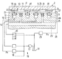
- the single figure shows a partial longitudinal section through a roller according to the invention with associated circuit.
- a roller 2 has a roller jacket 6, which is supported with the aid of support elements 10 on a non-rotatable support 9.
- the support element 10 is a ring element which encloses an interior 11. It is guided in a sealed manner in an annular groove 12, which forms a pressure space 14 delimited by a pressure surface 13. This is connected via a feed line 15 to a pressure fluid source 16, shown here by a pump 17 and a pressure control valve arrangement 18. Hydraulic fluid with an individually selectable pressure pk is supplied to the individual support elements 10 via the feed lines 15.
- the ring element 11 has a support surface 19 which faces the inner surface of the roll shell 6 and carries an annular pocket 20 which practically completely surrounds the interior 11 and is divided into several pocket sections by narrow crosspieces. Each pocket section is connected to the pressure chamber 14 via a line 22, which is provided with a throttle 23.
- the pocket area At is somewhat larger than the pressure area Ak.
- the ring element 11 has an extension 24 in the pocket area.
- each support element 10 has a cross-sectional area Ai and is connected via a drain line 25 running transversely in the support 9 to a common drain line 25 ', which is formed by an axial bore.
- a check valve 26 is installed in the discharge line 25, which opens towards the discharge side and acts as a switching valve.
- the common drain line 25 'outside the carrier 9 is connected to a changeover switch 30, which selectively locks the drain side of the check valve 26 with a blocking pressure from a pressure source, here the pump 17, or with an opening pressure from a pressure sink, here the container 31.
- a check valve 26 is assigned to each interior 11, which ensures that the interior pressures pi of the individual support elements 10 are decoupled from one another and are therefore able to follow the pocket pressure pt of the support element 10 in question. This is in contrast to the structurally simpler solution, in which a check valve common to all support elements is arranged in the common drain line 25 ', but such decoupling is not possible.
- the intermediate space 27 is connected to the container via a return line 28 which is provided with a pressure control valve 29. As a result, a pressure pu can be maintained in the intermediate space 27.
Landscapes
- Physics & Mathematics (AREA)
- Fluid Mechanics (AREA)
- Engineering & Computer Science (AREA)
- General Engineering & Computer Science (AREA)
- Mechanical Engineering (AREA)
- Paper (AREA)
- Rolls And Other Rotary Bodies (AREA)
- Treatment Of Fiber Materials (AREA)
- Casting Or Compression Moulding Of Plastics Or The Like (AREA)
Applications Claiming Priority (2)
| Application Number | Priority Date | Filing Date | Title |
|---|---|---|---|
| DE19540791 | 1995-11-02 | ||
| DE19540791A DE19540791C1 (de) | 1994-08-19 | 1995-11-02 | Durchbiegungssteuerbare Walze für einen Kalander o. dgl. |
Publications (3)
| Publication Number | Publication Date |
|---|---|
| EP0771905A2 true EP0771905A2 (fr) | 1997-05-07 |
| EP0771905A3 EP0771905A3 (fr) | 1998-07-01 |
| EP0771905B1 EP0771905B1 (fr) | 2001-06-13 |
Family
ID=7776413
Family Applications (1)
| Application Number | Title | Priority Date | Filing Date |
|---|---|---|---|
| EP96116465A Expired - Lifetime EP0771905B1 (fr) | 1995-11-02 | 1996-10-15 | Rouleau à réglage de la flexion pour une calandre ou similaire |
Country Status (4)
| Country | Link |
|---|---|
| US (1) | US5823927A (fr) |
| EP (1) | EP0771905B1 (fr) |
| JP (1) | JP2740761B2 (fr) |
| CA (1) | CA2187381C (fr) |
Cited By (1)
| Publication number | Priority date | Publication date | Assignee | Title |
|---|---|---|---|---|
| DE19929149A1 (de) * | 1999-06-27 | 2001-01-11 | Rust & Mitschke Entex | Walzen |
Families Citing this family (5)
| Publication number | Priority date | Publication date | Assignee | Title |
|---|---|---|---|---|
| FI116091B (fi) * | 2000-04-12 | 2005-09-15 | Metso Paper Inc | Menetelmä liukulaakeripaineen mittaamiseksi kiinteävaippaisessa taipumakompensoidussa telassa |
| CH695089A5 (de) * | 2001-09-18 | 2005-12-15 | Main Man Inspiration Ag | Giessrolle für eine Zweirollen-Giessmaschine. |
| DE102004022377A1 (de) * | 2004-05-06 | 2005-12-08 | Voith Paper Patent Gmbh | Biegeausgleichswalze |
| US7465264B2 (en) * | 2004-07-12 | 2008-12-16 | Rohm And Haas Denmark Finance A/S | Axially compliant pressure roller utilizing non-newtonian fluid |
| FR3055111B1 (fr) * | 2016-08-16 | 2018-08-31 | Safran Aircraft Engines | Installation et procede de mise en forme d'une preforme fibreuse de revolution presentant en section radiale un profil evolutif |
Family Cites Families (14)
| Publication number | Priority date | Publication date | Assignee | Title |
|---|---|---|---|---|
| US3587152A (en) * | 1968-06-12 | 1971-06-28 | Usm Corp | Controlled deflection roll |
| US4212504A (en) * | 1979-02-26 | 1980-07-15 | Bakanov Anatoly I | Backing device for a working roll of a roll stand |
| DE3022491C2 (de) * | 1980-06-14 | 1983-01-27 | Kleinewefers Gmbh, 4150 Krefeld | Druckbehandlungswalze |
| EP0273185B1 (fr) * | 1986-11-29 | 1990-10-31 | Eduard Küsters Maschinenfabrik GmbH & Co. KG | Rouleau à pression réglable le long d'une ligne |
| DE3820974C3 (de) * | 1988-06-22 | 1996-03-21 | Kuesters Eduard Maschf | Dichtungsglied bzw. Walze |
| DE3835152C1 (fr) * | 1988-10-15 | 1990-04-26 | Eduard Kuesters, Maschinenfabrik, Gmbh & Co Kg, 4150 Krefeld, De | |
| DE3918989C1 (fr) * | 1989-06-10 | 1990-12-13 | Eduard Kuesters Maschinenfabrik Gmbh & Co Kg, 4150 Krefeld, De | |
| DE4011826C1 (fr) * | 1990-04-12 | 1991-08-01 | Eduard Kuesters Maschinenfabrik Gmbh & Co Kg, 4150 Krefeld, De | |
| DE4030537C1 (fr) * | 1990-09-27 | 1991-10-10 | Kleinewefers Gmbh, 4150 Krefeld, De | |
| US5111565A (en) * | 1990-12-14 | 1992-05-12 | S.W. Industries, Inc. | Compensating roll assembly for flexible web material |
| DE4123115A1 (de) * | 1991-07-12 | 1993-01-14 | Voith Gmbh J M | Hydrostatisch gestuetzte durchbiegungsausgleichswalze, insbesondere fuer papiermaschinen |
| DE4429499C1 (de) * | 1994-08-19 | 1995-11-16 | Kleinewefers Gmbh | Durchbiegungssteuerbare Walze für einen Kalander o. dgl. |
| US5447605A (en) * | 1994-08-22 | 1995-09-05 | Beloit Technologies, Inc. | Position control for self-loading roll |
| US5650048A (en) * | 1996-01-31 | 1997-07-22 | Beloit Technologies, Inc. | Extended nip press with hydraulic pressure equalizer valve |
-
1996
- 1996-10-08 CA CA002187381A patent/CA2187381C/fr not_active Expired - Fee Related
- 1996-10-15 EP EP96116465A patent/EP0771905B1/fr not_active Expired - Lifetime
- 1996-10-23 US US08/736,355 patent/US5823927A/en not_active Expired - Fee Related
- 1996-10-24 JP JP8282003A patent/JP2740761B2/ja not_active Expired - Fee Related
Cited By (2)
| Publication number | Priority date | Publication date | Assignee | Title |
|---|---|---|---|---|
| DE19929149A1 (de) * | 1999-06-27 | 2001-01-11 | Rust & Mitschke Entex | Walzen |
| DE19929149B4 (de) * | 1999-06-27 | 2006-07-27 | Entex Rust & Mitschke Gmbh | Walzen |
Also Published As
| Publication number | Publication date |
|---|---|
| US5823927A (en) | 1998-10-20 |
| JP2740761B2 (ja) | 1998-04-15 |
| JPH09279495A (ja) | 1997-10-28 |
| CA2187381A1 (fr) | 1997-05-03 |
| EP0771905B1 (fr) | 2001-06-13 |
| CA2187381C (fr) | 1999-05-11 |
| EP0771905A3 (fr) | 1998-07-01 |
Similar Documents
| Publication | Publication Date | Title |
|---|---|---|
| DE2733054C2 (de) | Vorrichtung zur Zufuhr von unter Druck stehendem Fluid | |
| EP0854982B1 (fr) | Systeme de soupapes | |
| DE19931142C2 (de) | Hydraulische Ventilanordnung mit Verriegelungsfunktion | |
| DE102017206394A1 (de) | Druckhalteventilanordnung für einen Spülkreislauf eines geschlossenen hydraulischen Kreislaufs | |
| DE3422165A1 (de) | Hydraulische einrichtung mit einer pumpe und mindestens zwei von dieser beaufschlagten verbrauchern hydraulischer energie | |
| EP0667459B1 (fr) | Unité de soupape à électro-aimant proportionnel | |
| DE69417853T2 (de) | Hydraulische Servolenkung | |
| DE3437217A1 (de) | Fahrzeug-hoehenverstellsystem mit gleichfoermiger hoehensteuerung | |
| EP0935714B1 (fr) | Systeme de soupapes a balance de pression | |
| DE3802904A1 (de) | Servounterstuetzte lenkanlage | |
| EP0771905A2 (fr) | Rouleau à réglage de la flexion pour une calandre ou similaire | |
| DE19540791C1 (de) | Durchbiegungssteuerbare Walze für einen Kalander o. dgl. | |
| DE10316532B4 (de) | Hydraulisches Verstärkersystem für Bremsanlage | |
| DE3320047C2 (fr) | ||
| AT398114B (de) | Proportional-wegeventil | |
| DE3101968A1 (de) | Servolenkvorrichtung fuer fahrzeuge | |
| EP1342597B2 (fr) | Ensemble pour la stabilisation active de roulis d'un véhicule automobile | |
| DE2537957A1 (de) | Steuer- bzw. regelanordnung fuer pumpen mit variabler verdraengung | |
| DE2539522C2 (de) | Einrichtung zur Schmierölversorgung mehrerer Schmierstellen einer Brennkraftmaschine, insbesondere eines Großmotors | |
| DE4445589C2 (de) | Membrangesteuertes Ventil zur Aufrechterhaltung eines Differenzdrucks | |
| DE29508392U1 (de) | Elektrohydraulisches Hubmodul | |
| DE3147030C2 (de) | Magnetventileinheit | |
| DE3221160C2 (de) | Aus zwei Steuerblöcken bestehende Steuerventileinrichtung für mehrere hydraulische Antriebe, insbesondere von Mobilgeräten | |
| DE69505892T2 (de) | Servolenkung | |
| DE19642567C1 (de) | Kombiniertes Hydraulikventil mit einer Schalt- und einer Druckminderfunktion |
Legal Events
| Date | Code | Title | Description |
|---|---|---|---|
| PUAI | Public reference made under article 153(3) epc to a published international application that has entered the european phase |
Free format text: ORIGINAL CODE: 0009012 |
|
| AK | Designated contracting states |
Kind code of ref document: A2 Designated state(s): DE FI FR GB |
|
| PUAL | Search report despatched |
Free format text: ORIGINAL CODE: 0009013 |
|
| AK | Designated contracting states |
Kind code of ref document: A3 Designated state(s): DE FI FR GB |
|
| 17P | Request for examination filed |
Effective date: 19980612 |
|
| GRAG | Despatch of communication of intention to grant |
Free format text: ORIGINAL CODE: EPIDOS AGRA |
|
| GRAG | Despatch of communication of intention to grant |
Free format text: ORIGINAL CODE: EPIDOS AGRA |
|
| GRAH | Despatch of communication of intention to grant a patent |
Free format text: ORIGINAL CODE: EPIDOS IGRA |
|
| 17Q | First examination report despatched |
Effective date: 20001025 |
|
| RAP1 | Party data changed (applicant data changed or rights of an application transferred) |
Owner name: VOITH PAPER GMBH |
|
| RAP1 | Party data changed (applicant data changed or rights of an application transferred) |
Owner name: VOITH PAPER PATENT GMBH |
|
| GRAH | Despatch of communication of intention to grant a patent |
Free format text: ORIGINAL CODE: EPIDOS IGRA |
|
| GRAA | (expected) grant |
Free format text: ORIGINAL CODE: 0009210 |
|
| AK | Designated contracting states |
Kind code of ref document: B1 Designated state(s): DE FI FR GB |
|
| ET | Fr: translation filed | ||
| GBT | Gb: translation of ep patent filed (gb section 77(6)(a)/1977) |
Effective date: 20010625 |
|
| REF | Corresponds to: |
Ref document number: 59607074 Country of ref document: DE Date of ref document: 20010719 |
|
| REG | Reference to a national code |
Ref country code: GB Ref legal event code: IF02 |
|
| PLBE | No opposition filed within time limit |
Free format text: ORIGINAL CODE: 0009261 |
|
| STAA | Information on the status of an ep patent application or granted ep patent |
Free format text: STATUS: NO OPPOSITION FILED WITHIN TIME LIMIT |
|
| 26N | No opposition filed | ||
| PGFP | Annual fee paid to national office [announced via postgrant information from national office to epo] |
Ref country code: GB Payment date: 20030922 Year of fee payment: 8 |
|
| PG25 | Lapsed in a contracting state [announced via postgrant information from national office to epo] |
Ref country code: GB Free format text: LAPSE BECAUSE OF NON-PAYMENT OF DUE FEES Effective date: 20041015 |
|
| GBPC | Gb: european patent ceased through non-payment of renewal fee |
Effective date: 20041015 |
|
| PGFP | Annual fee paid to national office [announced via postgrant information from national office to epo] |
Ref country code: FR Payment date: 20051014 Year of fee payment: 10 |
|
| REG | Reference to a national code |
Ref country code: FR Ref legal event code: ST Effective date: 20070629 |
|
| PG25 | Lapsed in a contracting state [announced via postgrant information from national office to epo] |
Ref country code: FR Free format text: LAPSE BECAUSE OF NON-PAYMENT OF DUE FEES Effective date: 20061031 |
|
| PGFP | Annual fee paid to national office [announced via postgrant information from national office to epo] |
Ref country code: DE Payment date: 20101022 Year of fee payment: 15 |
|
| PGFP | Annual fee paid to national office [announced via postgrant information from national office to epo] |
Ref country code: FI Payment date: 20111013 Year of fee payment: 16 |
|
| REG | Reference to a national code |
Ref country code: DE Ref legal event code: R082 Ref document number: 59607074 Country of ref document: DE |
|
| PG25 | Lapsed in a contracting state [announced via postgrant information from national office to epo] |
Ref country code: DE Free format text: LAPSE BECAUSE OF NON-PAYMENT OF DUE FEES Effective date: 20130501 |
|
| REG | Reference to a national code |
Ref country code: DE Ref legal event code: R119 Ref document number: 59607074 Country of ref document: DE Effective date: 20130501 |
|
| PG25 | Lapsed in a contracting state [announced via postgrant information from national office to epo] |
Ref country code: FI Free format text: LAPSE BECAUSE OF NON-PAYMENT OF DUE FEES Effective date: 20121015 |