EP0771978A2 - Valve d'inversion et appareil de chauffage avec une valve d'inversion - Google Patents
Valve d'inversion et appareil de chauffage avec une valve d'inversion Download PDFInfo
- Publication number
- EP0771978A2 EP0771978A2 EP96116210A EP96116210A EP0771978A2 EP 0771978 A2 EP0771978 A2 EP 0771978A2 EP 96116210 A EP96116210 A EP 96116210A EP 96116210 A EP96116210 A EP 96116210A EP 0771978 A2 EP0771978 A2 EP 0771978A2
- Authority
- EP
- European Patent Office
- Prior art keywords
- reversing valve
- valve
- heating
- pump
- reversing
- Prior art date
- Legal status (The legal status is an assumption and is not a legal conclusion. Google has not performed a legal analysis and makes no representation as to the accuracy of the status listed.)
- Granted
Links
Images
Classifications
-
- F—MECHANICAL ENGINEERING; LIGHTING; HEATING; WEAPONS; BLASTING
- F16—ENGINEERING ELEMENTS AND UNITS; GENERAL MEASURES FOR PRODUCING AND MAINTAINING EFFECTIVE FUNCTIONING OF MACHINES OR INSTALLATIONS; THERMAL INSULATION IN GENERAL
- F16K—VALVES; TAPS; COCKS; ACTUATING-FLOATS; DEVICES FOR VENTING OR AERATING
- F16K11/00—Multiple-way valves, e.g. mixing valves; Pipe fittings incorporating such valves
- F16K11/02—Multiple-way valves, e.g. mixing valves; Pipe fittings incorporating such valves with all movable sealing faces moving as one unit
- F16K11/04—Multiple-way valves, e.g. mixing valves; Pipe fittings incorporating such valves with all movable sealing faces moving as one unit comprising only lift valves
- F16K11/048—Multiple-way valves, e.g. mixing valves; Pipe fittings incorporating such valves with all movable sealing faces moving as one unit comprising only lift valves with valve seats positioned between movable valve members
-
- F—MECHANICAL ENGINEERING; LIGHTING; HEATING; WEAPONS; BLASTING
- F24—HEATING; RANGES; VENTILATING
- F24D—DOMESTIC- OR SPACE-HEATING SYSTEMS, e.g. CENTRAL HEATING SYSTEMS; DOMESTIC HOT-WATER SUPPLY SYSTEMS; ELEMENTS OR COMPONENTS THEREFOR
- F24D19/00—Details
- F24D19/10—Arrangement or mounting of control or safety devices
- F24D19/1006—Arrangement or mounting of control or safety devices for water heating systems
- F24D19/1066—Arrangement or mounting of control or safety devices for water heating systems for the combination of central heating and domestic hot water
Definitions
- the invention relates to a reversing valve and a heater with a reversing valve according to the preambles of the independent claims.
- reversing valves are used when several heating circuits are supplied by one heater, the heating circuits usually being operated at different flow temperatures.
- Typical heating circuits for this are space heating and the provision of domestic hot water with an indirectly heated storage tank or a heat exchanger based on the instantaneous water heater principle.
- Known reversing valves have a closure body which can be moved back and forth between two closed positions by means of an actuating member. In each closed position, an input is blocked and another input is connected to an output of the changeover valve. The closing member is loaded in the opening direction by the pressure in the blocked inlet. It is unsatisfactory that a high closing force is required, which also depends on the pump pressure.
- the reversing valve according to the invention with the features of the main claim has the advantage that the pressures applied to the closure body of the valve member stresses the blocking closure member in the direction of the valve seat.
- the actuator must therefore only exert a high force during the movement of the valve member.
- the measures specified in the subclaims permit advantageous developments of the reversing valve according to the main claim.
- a particularly simple design results if the closure bodies are plate-shaped and are firmly connected to one another via a rod. The movement can then be linear or circular parallel to the rod.
- a further simplification results if the closure bodies are aligned parallel to one another and the rod connecting the closure bodies is also connected to the actuating member. This arrangement can be easily assembled and adjusted.
- valve member can advantageously be actuated electromagnetically. This can be done simply by the outwardly extended rod connecting the closure body. A defined zero position can be specified by the spring loading of the valve member.
- the reversing valve according to the invention advantageously supplements a heating device according to the invention if the inputs of the reversing valve are connected to returns of different heating circuits and the outlet of the reversing valve is connected to the heat exchanger of the heating device.
- a pump conveying the heating water is then preferably arranged behind the outlet of the reversing valve, as seen in the flow direction. This ensures that the Closure body only the pressures reduced by the pressure drops falling in the heat exchangers and heating circuits. This is particularly easy on the seal inside the valve seats. If the pump is switched off during the switching process, the forces to be exerted by the actuating member are low since the valve member does not have to be moved against the pump pressure.
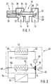
- Figure 1 shows schematically a reversing valve and Figure 2 schematically shows a heater.
- a reversing valve 10 is shown with a housing 12 which has three connections 14, 16 and 18.
- a valve member 20 Arranged within the housing 12 is a valve member 20 which has two closure bodies 22 and 24, the closure body 22 corresponding to a valve seat 26 and the closure body 24 corresponding to a valve seat 28.
- the two closure bodies 22 and 24 are aligned parallel to one another and connected to one another via a rod 30.
- the rod 30 is displaceably held on the side of the closure body (24) in a bearing (32) and extended on the side of the closure body 22 on the side opposite the closure body 24.
- the extension 34 of the rod 30 protrudes into a coil 36 which is attached to the side of the housing 12.
- a spring 38 is inserted between the coil 36 and the closure body 22.
- the elongated rod 30, the coil 36 and the spring 38 together form an actuator 37.
- the distance between the closure bodies 22 and 24 from one another is greater than the distance between the valve seats 26 and 28. In this way, only one closure body 22 or 24 can rest on the valve seat 26 or 28 corresponding to it.
- FIG. 2 shows a heater 40 with a heat exchanger 42, which is supplied with heat by an energy source 44.
- An inner pipeline system 46 through which the heat exchanger 42 is also arranged, leads through the heater 40.
- the pipe system 46 has a branch 48, from which a first pipe branch 50 leads to a heater 40 arranged heat exchanger system 52 and from there to the reversing valve 10.
- a second pipe run 54 leaves the heater and leads to a schematically illustrated heating circuit 56, from there back to the heater 40 and also to the reversing valve 10.
- the heat transfer system 52 is preferably used for domestic water preparation and the heating circuit 56 for space heating.
- a pump 58 which pumps the heating water is also integrated in the inner pipeline system 46 in the heater 40.
- the pump 58 is located between the changeover valve 10 and the heat exchanger 42.
- the connection 14 of the changeover valve 10 is connected to the heating circuit 56, the connection 16 to the heat transfer system 52 and the connection 18 to the input of the pump 58.
- Reversing valve 10 and heater 40 operate as follows:
- thermal energy is transferred to a heating medium via the heat exchanger 42 and pumped through the pipeline system 46 while the pump 58 is running.
- the heating medium flows into the pipeline 54 and through the heating circuit 56 to the connection 14 of the reversing valve 10.
- the closure body 22 is lifted off the valve seat 26, so that the heating medium can flow from the connection 14 to the connection 18. From there the heating medium reaches the inlet of the pump 48 and the circuit is closed.
- the pressure generated by the pump 58 continues in the pipeline string 50 through the heat transfer system 52 to the connection 16 of the reversing valve 10.
- the full pressure of the pump 58 prevails on the connection side 16 of the closure body 24 less the pressure loss within the heat exchanger 42.
- the pump pressure prevails less the pressure loss within the heat exchanger 42, further reduced by the pressure loss within the heating circuit 56 and further reduced by the dynamic pressure generated by the speed of the heating medium.
- the closure body 24 is consequently pressed onto the valve seat 28 by the pressure difference prevailing thereon.
- the electrical coil 36 is deactivated and the extension 34 of the rod 30 is no longer held in the coil 36 and is pulled out of the coil 36 only by the spring.
- the closure body 24 lifts off from the valve seat 28 and the closure body 22 lies on the valve seat 26. The direction of passage from port 14 to port 18 is thus blocked and the passage from port 16 to port 18 is open.
- the heating medium thus flows through the heat transfer system 52. With the pump 58 running is pressed by the prevailing pressure conditions of the closure body 22 on the valve seat 26.
- the pump can also be operated with reduced power during the changeover.
Landscapes
- Engineering & Computer Science (AREA)
- General Engineering & Computer Science (AREA)
- Mechanical Engineering (AREA)
- Physics & Mathematics (AREA)
- Thermal Sciences (AREA)
- Chemical & Material Sciences (AREA)
- Combustion & Propulsion (AREA)
- Multiple-Way Valves (AREA)
- Steam Or Hot-Water Central Heating Systems (AREA)
Applications Claiming Priority (2)
| Application Number | Priority Date | Filing Date | Title |
|---|---|---|---|
| DE19540816A DE19540816A1 (de) | 1995-11-02 | 1995-11-02 | Umsteuerventil sowie Heizgerät mit einem Umsteuerventil |
| DE19540816 | 1995-11-02 |
Publications (3)
| Publication Number | Publication Date |
|---|---|
| EP0771978A2 true EP0771978A2 (fr) | 1997-05-07 |
| EP0771978A3 EP0771978A3 (fr) | 1997-07-09 |
| EP0771978B1 EP0771978B1 (fr) | 2001-12-19 |
Family
ID=7776427
Family Applications (1)
| Application Number | Title | Priority Date | Filing Date |
|---|---|---|---|
| EP96116210A Expired - Lifetime EP0771978B1 (fr) | 1995-11-02 | 1996-10-10 | Appareil de chauffage avec une valve d'inversion |
Country Status (2)
| Country | Link |
|---|---|
| EP (1) | EP0771978B1 (fr) |
| DE (2) | DE19540816A1 (fr) |
Cited By (3)
| Publication number | Priority date | Publication date | Assignee | Title |
|---|---|---|---|---|
| DE10058516A1 (de) * | 2000-11-24 | 2002-05-29 | Obrist Engineering Gmbh Lusten | Mehrwegeventil |
| EP0994311A3 (fr) * | 1998-10-14 | 2002-09-18 | Fugas Spa | Ensemble hydraulique pour systéme de chauffage mixte, avec accumulateur d'eau chaude |
| CN106801748A (zh) * | 2016-12-16 | 2017-06-06 | 无锡锡通工程机械有限公司 | 一种干砂仓除湿除尘系统用远程控制电动转换阀 |
Families Citing this family (4)
| Publication number | Priority date | Publication date | Assignee | Title |
|---|---|---|---|---|
| DE10100886A1 (de) * | 2001-01-11 | 2002-08-14 | Bosch Gmbh Robert | Umsteuerventil für eine Heizungsanlage |
| DE10111886A1 (de) * | 2001-03-13 | 2002-10-02 | Eberspaecher J Gmbh & Co | Abgaskühlelement für einen Abgasstrang einer Brennkraftmaschine |
| DE10222936A1 (de) * | 2002-05-24 | 2003-12-04 | Zahnradfabrik Friedrichshafen | Proportional-Druckregelventil |
| EP3156659B1 (fr) * | 2015-10-12 | 2020-09-16 | Grundfos Holding A/S | Pompe et système hydraulique |
Family Cites Families (6)
| Publication number | Priority date | Publication date | Assignee | Title |
|---|---|---|---|---|
| DE7235386U (de) * | 1972-12-14 | Lins A | Umsteuerventil | |
| DE242681C (fr) * | ||||
| FR1020134A (fr) * | 1950-06-13 | 1953-02-02 | Perfectionnements aux vannes à trois voies pour fluides sous pression | |
| AT394771B (de) * | 1989-11-07 | 1992-06-25 | Vaillant Gmbh | Verfahren und einrichtung zur durchfuehrung des verfahrens zum sofortigen zapfen von warmem brauchwasser |
| IT1244296B (it) * | 1990-07-09 | 1994-07-08 | Giuseppe Fugazza | Complesso valvolare per impianti di riscaldamento |
| AT399941B (de) * | 1993-06-16 | 1995-08-25 | Vaillant Gmbh | Einrichtung bei einer heizungsanlage |
-
1995
- 1995-11-02 DE DE19540816A patent/DE19540816A1/de not_active Withdrawn
-
1996
- 1996-10-10 EP EP96116210A patent/EP0771978B1/fr not_active Expired - Lifetime
- 1996-10-10 DE DE59608493T patent/DE59608493D1/de not_active Expired - Fee Related
Cited By (4)
| Publication number | Priority date | Publication date | Assignee | Title |
|---|---|---|---|---|
| EP0994311A3 (fr) * | 1998-10-14 | 2002-09-18 | Fugas Spa | Ensemble hydraulique pour systéme de chauffage mixte, avec accumulateur d'eau chaude |
| DE10058516A1 (de) * | 2000-11-24 | 2002-05-29 | Obrist Engineering Gmbh Lusten | Mehrwegeventil |
| DE10058516B4 (de) * | 2000-11-24 | 2006-09-07 | Audi Ag | Mehrwegeventil |
| CN106801748A (zh) * | 2016-12-16 | 2017-06-06 | 无锡锡通工程机械有限公司 | 一种干砂仓除湿除尘系统用远程控制电动转换阀 |
Also Published As
| Publication number | Publication date |
|---|---|
| DE19540816A1 (de) | 1997-05-07 |
| EP0771978A3 (fr) | 1997-07-09 |
| EP0771978B1 (fr) | 2001-12-19 |
| DE59608493D1 (de) | 2002-01-31 |
Similar Documents
| Publication | Publication Date | Title |
|---|---|---|
| DE3614425A1 (de) | Elektromagnetische mehrfunktions-absperrorgananordnung | |
| EP3077712B1 (fr) | Soupape à solénoïde | |
| DE112007001455T5 (de) | Strömungsmittelgesteuertes Ventil | |
| DE3444417A1 (de) | Schwenkschieberventil | |
| DE3514198C2 (de) | Einrichtung zum Beheizen des Fahrgastraumes eines Kraftfahrzeugs | |
| DE10023329A1 (de) | Ventil | |
| DE102012013594A1 (de) | Leitungssystem zum Transport von Flüssigkeiten | |
| EP0771978B1 (fr) | Appareil de chauffage avec une valve d'inversion | |
| EP0529353B1 (fr) | Chaudière à gaz | |
| EP1650434B1 (fr) | Compresseur à pistons multi-étages ayant un gain en puissance réduit à vide | |
| DE2241504B2 (de) | Zentralheizungssystem mit Dreiwegeventil zum Umsteuern des Wärmemediums zu Heizkörpern oder zu einem Brauchwasser-Wärmetauscher | |
| DE3907378A1 (de) | Ventilanordnung zum gleichzeitigen oeffnen und absperren zweier getrennter zuleitungen fuer fluessige oder gasfoermige medien | |
| DE19824630B4 (de) | Ventilkombination aus einem Membranregler, einer Drossel und einem Regelventil | |
| EP3563207A1 (fr) | Vanne de régulation pour régler la pression différentielle et/ou le débit volumique | |
| DE3822830A1 (de) | Eigenmediumbetaetigtes, durch ein bistabiles magnetventil servogesteuertes ventil fuer fluessige medien | |
| EP2184520B1 (fr) | Soupape dotée d'un dispositif contre les coups des bélier | |
| EP0988163A1 (fr) | Electrovanne pour systeme de chauffage et/ou de refroidissement regule par liquide | |
| DE4127822A1 (de) | Gastherme | |
| DE29611368U1 (de) | Heizgerät mit einem Umsteuerventil | |
| EP1754916B1 (fr) | Clapet avec un élément piézo-électrique | |
| DE1650504A1 (de) | Ventileinheit | |
| DE4039644A1 (de) | Ueberstroemventil | |
| DE2829528C2 (de) | Kombinierte Überdruck-Spülventilanordnung für ein hydrostatisches Getriebe, insbesondere zum Antrieb von Fahrzeugen | |
| DE303768C (fr) | ||
| AT230519B (de) | Vorrichtung zur Verhinderung des Nachspritzens von Öl aus der Düse bei Druckölbrennern |
Legal Events
| Date | Code | Title | Description |
|---|---|---|---|
| PUAI | Public reference made under article 153(3) epc to a published international application that has entered the european phase |
Free format text: ORIGINAL CODE: 0009012 |
|
| AK | Designated contracting states |
Kind code of ref document: A2 Designated state(s): DE FR GB IT NL |
|
| PUAL | Search report despatched |
Free format text: ORIGINAL CODE: 0009013 |
|
| AK | Designated contracting states |
Kind code of ref document: A3 Designated state(s): DE FR GB IT NL |
|
| 17P | Request for examination filed |
Effective date: 19980109 |
|
| 17Q | First examination report despatched |
Effective date: 19991202 |
|
| GRAG | Despatch of communication of intention to grant |
Free format text: ORIGINAL CODE: EPIDOS AGRA |
|
| RIC1 | Information provided on ipc code assigned before grant |
Free format text: 7F 16K 11/048 A, 7F 24D 3/08 B, 7F 24D 19/10 B |
|
| RTI1 | Title (correction) |
Free format text: HEATING DEVICE WITH A REVERSIBLE VALVE |
|
| RIC1 | Information provided on ipc code assigned before grant |
Free format text: 7F 16K 11/048 A, 7F 24D 3/08 B, 7F 24D 19/10 B |
|
| RTI1 | Title (correction) |
Free format text: HEATING DEVICE WITH A REVERSIBLE VALVE |
|
| RIC1 | Information provided on ipc code assigned before grant |
Free format text: 7F 16K 11/048 A, 7F 24D 3/08 B, 7F 24D 19/10 B |
|
| RTI1 | Title (correction) |
Free format text: HEATING DEVICE WITH A REVERSIBLE VALVE |
|
| GRAG | Despatch of communication of intention to grant |
Free format text: ORIGINAL CODE: EPIDOS AGRA |
|
| GRAH | Despatch of communication of intention to grant a patent |
Free format text: ORIGINAL CODE: EPIDOS IGRA |
|
| GRAH | Despatch of communication of intention to grant a patent |
Free format text: ORIGINAL CODE: EPIDOS IGRA |
|
| GRAA | (expected) grant |
Free format text: ORIGINAL CODE: 0009210 |
|
| AK | Designated contracting states |
Kind code of ref document: B1 Designated state(s): DE FR GB IT NL |
|
| REG | Reference to a national code |
Ref country code: GB Ref legal event code: IF02 |
|
| REF | Corresponds to: |
Ref document number: 59608493 Country of ref document: DE Date of ref document: 20020131 |
|
| GBT | Gb: translation of ep patent filed (gb section 77(6)(a)/1977) |
Effective date: 20020311 |
|
| PGFP | Annual fee paid to national office [announced via postgrant information from national office to epo] |
Ref country code: GB Payment date: 20020919 Year of fee payment: 7 |
|
| PGFP | Annual fee paid to national office [announced via postgrant information from national office to epo] |
Ref country code: FR Payment date: 20021018 Year of fee payment: 7 |
|
| PGFP | Annual fee paid to national office [announced via postgrant information from national office to epo] |
Ref country code: NL Payment date: 20021022 Year of fee payment: 7 |
|
| PLBE | No opposition filed within time limit |
Free format text: ORIGINAL CODE: 0009261 |
|
| STAA | Information on the status of an ep patent application or granted ep patent |
Free format text: STATUS: NO OPPOSITION FILED WITHIN TIME LIMIT |
|
| 26N | No opposition filed | ||
| PG25 | Lapsed in a contracting state [announced via postgrant information from national office to epo] |
Ref country code: GB Free format text: LAPSE BECAUSE OF NON-PAYMENT OF DUE FEES Effective date: 20031010 |
|
| PGFP | Annual fee paid to national office [announced via postgrant information from national office to epo] |
Ref country code: DE Payment date: 20031215 Year of fee payment: 8 |
|
| PG25 | Lapsed in a contracting state [announced via postgrant information from national office to epo] |
Ref country code: NL Free format text: LAPSE BECAUSE OF NON-PAYMENT OF DUE FEES Effective date: 20040501 |
|
| GBPC | Gb: european patent ceased through non-payment of renewal fee |
Effective date: 20031010 |
|
| PG25 | Lapsed in a contracting state [announced via postgrant information from national office to epo] |
Ref country code: FR Free format text: LAPSE BECAUSE OF NON-PAYMENT OF DUE FEES Effective date: 20040630 |
|
| NLV4 | Nl: lapsed or anulled due to non-payment of the annual fee |
Effective date: 20040501 |
|
| REG | Reference to a national code |
Ref country code: FR Ref legal event code: ST |
|
| PG25 | Lapsed in a contracting state [announced via postgrant information from national office to epo] |
Ref country code: DE Free format text: LAPSE BECAUSE OF NON-PAYMENT OF DUE FEES Effective date: 20050503 |
|
| PG25 | Lapsed in a contracting state [announced via postgrant information from national office to epo] |
Ref country code: IT Free format text: LAPSE BECAUSE OF NON-PAYMENT OF DUE FEES;WARNING: LAPSES OF ITALIAN PATENTS WITH EFFECTIVE DATE BEFORE 2007 MAY HAVE OCCURRED AT ANY TIME BEFORE 2007. THE CORRECT EFFECTIVE DATE MAY BE DIFFERENT FROM THE ONE RECORDED. Effective date: 20051010 |