EP0772003A1 - Gerät zum Absaugen eines Gases aus einer Leitung um es abzuführen - Google Patents
Gerät zum Absaugen eines Gases aus einer Leitung um es abzuführen Download PDFInfo
- Publication number
- EP0772003A1 EP0772003A1 EP96402337A EP96402337A EP0772003A1 EP 0772003 A1 EP0772003 A1 EP 0772003A1 EP 96402337 A EP96402337 A EP 96402337A EP 96402337 A EP96402337 A EP 96402337A EP 0772003 A1 EP0772003 A1 EP 0772003A1
- Authority
- EP
- European Patent Office
- Prior art keywords
- nozzles
- section
- gaseous
- duct
- fluid
- Prior art date
- Legal status (The legal status is an assumption and is not a legal conclusion. Google has not performed a legal analysis and makes no representation as to the accuracy of the status listed.)
- Granted
Links
Images


Classifications
-
- F—MECHANICAL ENGINEERING; LIGHTING; HEATING; WEAPONS; BLASTING
- F23—COMBUSTION APPARATUS; COMBUSTION PROCESSES
- F23L—SUPPLYING AIR OR NON-COMBUSTIBLE LIQUIDS OR GASES TO COMBUSTION APPARATUS IN GENERAL ; VALVES OR DAMPERS SPECIALLY ADAPTED FOR CONTROLLING AIR SUPPLY OR DRAUGHT IN COMBUSTION APPARATUS; INDUCING DRAUGHT IN COMBUSTION APPARATUS; TOPS FOR CHIMNEYS OR VENTILATING SHAFTS; TERMINALS FOR FLUES
- F23L17/00—Inducing draught; Tops for chimneys or ventilating shafts; Terminals for flues
- F23L17/16—Induction apparatus, e.g. steam jet, acting on combustion products beyond the fire
-
- F—MECHANICAL ENGINEERING; LIGHTING; HEATING; WEAPONS; BLASTING
- F23—COMBUSTION APPARATUS; COMBUSTION PROCESSES
- F23L—SUPPLYING AIR OR NON-COMBUSTIBLE LIQUIDS OR GASES TO COMBUSTION APPARATUS IN GENERAL ; VALVES OR DAMPERS SPECIALLY ADAPTED FOR CONTROLLING AIR SUPPLY OR DRAUGHT IN COMBUSTION APPARATUS; INDUCING DRAUGHT IN COMBUSTION APPARATUS; TOPS FOR CHIMNEYS OR VENTILATING SHAFTS; TERMINALS FOR FLUES
- F23L17/00—Inducing draught; Tops for chimneys or ventilating shafts; Terminals for flues
- F23L17/005—Inducing draught; Tops for chimneys or ventilating shafts; Terminals for flues using fans
-
- F—MECHANICAL ENGINEERING; LIGHTING; HEATING; WEAPONS; BLASTING
- F23—COMBUSTION APPARATUS; COMBUSTION PROCESSES
- F23L—SUPPLYING AIR OR NON-COMBUSTIBLE LIQUIDS OR GASES TO COMBUSTION APPARATUS IN GENERAL ; VALVES OR DAMPERS SPECIALLY ADAPTED FOR CONTROLLING AIR SUPPLY OR DRAUGHT IN COMBUSTION APPARATUS; INDUCING DRAUGHT IN COMBUSTION APPARATUS; TOPS FOR CHIMNEYS OR VENTILATING SHAFTS; TERMINALS FOR FLUES
- F23L17/00—Inducing draught; Tops for chimneys or ventilating shafts; Terminals for flues
- F23L17/02—Tops for chimneys or ventilating shafts; Terminals for flues
- F23L17/08—Tops for chimneys or ventilating shafts; Terminals for flues with coaxial cones or louvres
-
- F—MECHANICAL ENGINEERING; LIGHTING; HEATING; WEAPONS; BLASTING
- F24—HEATING; RANGES; VENTILATING
- F24F—AIR-CONDITIONING; AIR-HUMIDIFICATION; VENTILATION; USE OF AIR CURRENTS FOR SCREENING
- F24F7/00—Ventilation
- F24F7/02—Roof ventilation
- F24F7/025—Roof ventilation with forced air circulation by means of a built-in ventilator
Definitions
- the invention relates to a device for sucking a gaseous fluid through a main duct to discharge it outside, intended for the evacuation of ventilation air, gases, fumes, products of combustion from industrial, work, residential or other premises.
- the invention also relates to an installation comprising such a device.
- a device for activating the ventilation of an air extraction duct including a medium-pressure blown air nozzle located either in the axis of the duct. , either laterally depending on whether it is a question of increasing or slowing down the extracted air flow.
- a static extractor is defined as being a “device without moving parts intended to be installed on top of ventilation or smoke ducts, having the objective, by creating a depression as a function of the wind speed, of opposing reversals of circulation of air flows and to increase the extracted flows in the presence of wind.
- static mechanical extractors as "static extractors equipped with a complementary device using an energy source other than that of the wind”.
- the object of the invention is to further improve the draft, whether it is natural or improved as a result of the presence of a static or stato-mechanical vacuum cleaner.
- the invention also aims to obtain this result without substantially increasing the complexity of the device used.
- the invention relates to a device for sucking a gaseous fluid through a main duct to discharge it outside thereof, intended for the evacuation of ventilation air, gases, fumes, combustion from industrial, working, residential or other premises, which comprises, in combination, in the first place, a section of duct, essentially straight, of a certain axial length, intended to be downstream of the main duct by relation to the direction of circulation of the gaseous fluid to be discharged and, secondly, means of injecting a gaseous driving fluid into the section of conduit, in the same direction as the direction of circulation of the gaseous fluid to be discharged, intended to be associated with means for producing the drive of said gaseous drive fluid, located at a certain distance upstream from the downstream end of the section of pipe as a function of the length of the main pipe, so that the spacing is on the one hand between 0.1 and 20% of the length of the main duct and more particularly of the order of 10% and, on the other hand, between 50 cm and 2 m,
- the invention relates to a device for sucking a gaseous fluid through a main conduit to discharge it outside of it which comprises, in combination, firstly, the section of conduit previously mentioned, in second, a static or statomechanical vacuum cleaner mounted on the section of conduit at its downstream end and, thirdly, means for injecting a gaseous drive fluid into the pipe section and through the static or statomechanical vacuum cleaner, in the same direction as the direction of circulation of the gaseous fluid to be discharged, intended to be associated with means for producing or driving said gaseous drive fluid, located at a certain distance upstream from the downstream end of the duct section and from the static or statomechanical vacuum cleaner.
- the static or stato-mechanical vacuum cleaner it is of the type comprising a lower part and an upper part spaced from one another and rigidly associated with each other along the axis of the section of conduit, the lower part being provided with a hole for the passage of the gaseous fluid to be discharged and the gaseous drive fluid, in communication with the section of conduit, this hole opening into the space existing between the lower part and the upper part.
- the space between the lower and upper parts has in axial section a general form of venturi.
- the static or stato-mechanical vacuum cleaner has a general shape of revolution whose axis is in the extension of that of the duct section or slightly inclined with respect to it.
- the lower part of the static or statomechanical vacuum cleaner comprises at least one upper wall of generally frustoconical shape, the small base of which faces the upper part and the large base of which faces the duct section.
- the lower part of the static or statomechanical vacuum cleaner also comprises a lower wall of generally frustoconical shape, the small base of which faces the duct section and the large base towards the upper wall of said lower part.
- the upper part of the static or statomechanical vacuum cleaner comprises at least one lower wall of generally conical or frustoconical shape, the point or the small base of which faces the lower part and the large base opposite the section of duct.
- the upper part of the static or statomechanical vacuum cleaner also comprises an upper wall of generally conical or frustoconical or hemispherical shape, the large base of which faces the lower wall of said upper part.
- the upper part and the lower part have substantially the same outside diameter.
- the static or stato-mechanical vacuum cleaner includes spacers for reciprocal attachment of the two lower and upper parts, associated in particular with the upper wall of the lower part and with the lower wall of the upper part.
- the constitutive walls of the lower and upper parts of the static or stato-mechanical vacuum cleaner are full, devoid of openings.
- the static or stato-mechanical vacuum cleaner also has a ferrule adjoining the lower part, intended for fixing the vacuum cleaner to the duct section.
- the vacuum cleaner is static and has no moving parts, in particular no integrated turbine.
- the vacuum cleaner is stato-mechanical and it also includes, for this purpose, an integrated turbine.
- Such a turbine has its blades located in the space existing between the lower and upper parts or that formed by the upper part.
- the section of conduit is either distinct from the main conduit and rigidly associated with it by bolting, welding, strapping or other, or it forms a single piece with it, the section of conduit forming the downstream end portion of the main conduit.
- the duct section can be an integral part of the static or statomechanical vacuum cleaner by being constituted by the ferrule with which the latter is provided, the latter having an axial length sufficient to allow mounting on the main duct. .
- the pipe section and the main pipe have the same diameter or substantially the same diameter. They are coaxial or their respective axes are slightly inclined relative to each other.
- these means comprise one or more injection nozzles or equivalent located inside the section of pipe and carried by it and one or more pipes injection, in communication with the nozzle (s), essentially located outside the pipe section as well as the main pipe.
- This or these injection conduits are located essentially upstream of the nozzles.
- the injection nozzle (s) have a generally fixed position in the pipe section, at least as regards their spacing with respect to the axis of the pipe section.
- injection nozzles arranged in different places of the duct section, in the axis and / or spaced from it.
- the plurality of injection nozzles is located substantially in the same transverse plane of the duct section or in several transverse planes of the duct section. In this case, the latter include an upstream plane and a downstream plane.
- this plurality comprises one or more central nozzles located in or near the axis of the duct section and / or a plurality of peripheral nozzles located near the wall of the duct section and / or a plurality of median nozzles located between the axis of the duct section and its wall.
- the peripheral and / or median nozzles are regularly distributed around the axis of the duct section.
- the different injection nozzles are arranged in relation to each other so as not to substantially obstruct the passage of the gaseous fluid to be discharged coming from upstream of the nozzles through the main conduit.
- the injection nozzles are arranged in rows and columns carried by a perforated plate located in the section of duct and carried by it.
- the device comprises a plurality of injection nozzles or equivalent
- the physical characteristics such as, in particular, flow rate, speed and opening of the beam of the flow of gaseous drive fluid injected by the different nozzles are identical or similar.
- these physical characteristics are differentiated between the nozzles according to the requirements required.
- the device comprises means for adjusting the physical characteristics in question for the different injection nozzles or over time.
- the spacing between the different nozzles and the downstream end of the duct section or the static or statomechanical vacuum cleaner is identical or differentiated according to the nozzles according to the requirements required.
- At least one or some nozzles are mounted slidingly adjustable parallel to the axis of the section of conduit between two extreme positions, respectively distal and proximal.
- the device comprises sliding guide means of the adjustable sliding nozzle (s), means for driving the nozzles and means for controlling the driving means.
- the space located downstream of the injection nozzles is free or, on the contrary, one or more walls in the form of a venturi are provided at this location.
- the device may include a wall in the form of a venturi adjoining the wall of the section of conduit. or / and a wall in the form of a venturi for one or more injection nozzles, in particular of the same kind, central, peripheral or median.
- an injection nozzle is chosen to provide an injection flow in the form of a narrow beam or of a wide beam, or of a spiral jet.
- An injection nozzle is either of fixed axis, in particular parallel to the axis of the duct section or inclined thereon, or of displaceable axis, the device then being provided with means for moving the axis of the displaceable nozzles and of means for controlling the displacement means.
- the device also comprises means for modulating the flow rate and / or the speed of the flow of gaseous drive fluid as a function of the requirements required.
- modulation means include means for controlling the triggering of the injection of gaseous drive fluid such as clock, temperature probe, pressure switch, hydrostatic probe.
- the invention also relates to an installation comprising one or more main conduits, one or more devices as described above and means for producing and driving the gaseous drive fluid.
- the means for producing and driving a gaseous drive fluid can be common to several conduits and they can be separated from the suction and drive device (s).
- FIG. 1 is a purely schematic view of an installation comprising a device according to the invention.
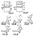
- Figures 2a to 2k are eleven partial schematic figures illustrating several embodiments of the means for injecting a gaseous drive fluid.
- Figures 3a to 3e are five schematic views, on a larger scale, illustrating different alternative embodiments of nozzles or the like of said injection means.
- the invention relates to a device 1 for sucking a gaseous fluid through a main conduit 2 to discharge it outside thereof.
- Such a device 1 is intended more specifically for the evacuation of ventilation air, gases, fumes, combustion products from industrial, work, residential or other premises.
- Such a device alone or associated with other similar ones, can be incorporated in an installation comprising one or more main duct (s) such as 2.
- Such an installation also includes means 3 for producing and driving a gaseous drive fluid.
- the means 3 for producing and driving a gaseous driving fluid can be separated from the device (s) 1.
- the main duct (s) 2 are generally arranged vertically and the device (s) 1 placed at the top of these.
- the means 3 for producing, for driving gaseous driving fluid are preferably placed on the ground, or even in the basement.
- the device 1 comprises in combination, in the first place, a section of conduit 4 of axis 4a, essentially rectilinear, of a certain axial length.
- the pipe section 4 is intended to be downstream of the main pipe 2 of axis 2a, relative to the direction of circulation of the gaseous fluid to be discharged.
- the pipe section 4 is associated with the end part 5 of the pipe 2.
- the main conduit 2 has one or more inlets 6 for the gaseous fluid to be discharged.
- the main duct 2 extends over a certain axial length, and there are provided several inlets 6 spaced along the axis 2a corresponding for example to different floors of the building for which the device 1 is intended and the installation that incorporates it.
- the main duct can, if necessary, be doubled with a duct which adjoins it, corresponding to a last floor of the building.
- the inlets 6 can be associated with horizontal ducts in which the nozzles for injecting gaseous fluid are also mounted.
- the device 1 comprises, in the embodiment shown in Figure 1, secondly, a static vacuum cleaner 7 shown purely schematically.
- This static vacuum cleaner 7 is mounted on the duct section 4 at its downstream end with respect to the direction of circulation of the gaseous fluids to be discharged and of drive. This means that the static vacuum cleaner 7 is, in the embodiment more especially considered, located in part upper end of the 4 in the upper extreme part of the duct section 4.
- the static vacuum cleaner 7 can be of the statomechanical type rather than static.
- the device 1 also comprises, thirdly, means 8 for injecting a gaseous drive fluid into the section of conduit 4 in the same direction as the direction of circulation of the gaseous fluid to be discharged.
- the injection means 8 are intended to be associated with the means 3 for producing and driving the gaseous drive fluid.
- the injection means 8 are located being spaced a certain distance upstream from the downstream end 9 of the section of conduit 4.
- the injection means 8 also inject a gaseous drive fluid through the static aspirator 7 or statomechanical.
- the injection means 8 are also spaced from said static or stato-mechanical vacuum cleaner 7.
- the pipe section 4 is associated by its upstream end 10 with the upper end part 5 of the main pipe 2.
- the spacing between the injection means 8 and the downstream end 9 of the pipe section 4 is a function in particular of the length of the main pipe 2.
- the spacing between the injection means 8 and the downstream end 9 of the pipe section 4 is between 0.1 and 20% of the length of the main pipe 2 and more specifically, is of the order of 10% this length.
- this spacing is between 50 cm and 2 m, more particularly between 75 cm and 1.25 m. It is more particularly of the order of 1 m.
- the length of the main duct 2 to which reference is made is the so-called useful length, that is to say that which extends between the most extreme lower inlet 6 (i.e. say the most removed from the device 1) and the device 1 in question, respectively the vacuum cleaner 7.
- the means 8 for injecting the gaseous driving fluid as well as the means 3 for producing and driving said gaseous fluid are designed and arranged to be able to allow on the one hand a flow of gaseous driving fluid between 20 and 100% of the nominal flow rate of gaseous fluid in the main duct 2 and more especially between 20 and 60% and, on the other hand, a speed of the gaseous drive fluid between 10 and 100 m / s, and more especially between 20 and 60 m / s, this for the applications considered.
- one or more sections 4 may be provided, depending on the embodiments envisaged. Consequently, the means 8 are themselves single or multiple.
- a static vacuum cleaner such as 7 or a static mechanical vacuum cleaner can be the subject of numerous variant embodiments.
- a static mechanical vacuum cleaner is more specifically described in the following documents also incorporated in the present description.
- a static vacuum cleaner 7 will therefore now be described, more particularly with reference to FIG. 1.
- the static vacuum cleaner 7 is of the type comprising a lower part 11, an upper part 12 coaxial with axis 13, of revolution about this axis, and the outside diameter of which is identical or substantially the same.
- the two lower parts 11 and upper 12 are spaced from one another to provide between them a free space 14 having in axial section a general shape of venturi.
- the lower 11 and upper 12 parts are rigidly associated with one another by means of reciprocal securing spacers 15.
- these spacers 15 are in the form of flat sections, these are radial planes to avoid excessive wind resistance.
- the duct section 4 can form a diffuser in the lower part 11.
- there can be a cross.
- the axis 13 is coaxial with the axis 4a. In other embodiments not shown, the axis 13 can be slightly inclined relative to the axis 4a and relative to the vertical.
- the lower part 11 comprises, in the embodiment shown, an upper wall 17 and a lower wall 18.
- Both the upper wall 17 and the lower wall 18 have a generally frustoconical shape.
- the small base 19 of the upper wall 17 is turned towards the upper part 12 and the space 14.
- the large base 20 of the upper wall 17 faces the duct section 4 and it is common with the large base of the wall lower 18 whose small base is turned towards 4 whose small base is turned towards the duct section 4.
- the upper part 12 has a lower wall 21 and an upper wall 22.
- the bottom wall 21 has, in the embodiment shown, a generally conical shape. In another possible embodiment, the bottom wall 21 has a generally frustoconical shape. In one as in the other of the possible embodiments, the point 23 or the small base of the lower wall 21 is turned towards the lower part 12, that is to say towards the space 14. The large base 24 is in turn opposite to the section of conduit 4.
- the upper wall 22 has, in the embodiment shown, a generally conical shape. In other embodiments, the upper wall 22 has a generally frustoconical or hemispherical shape, or a complex shape derived from the preceding shapes.
- the upper wall 22 has a large base common with the large base 24. It therefore faces the lower part 11.
- the spacers 15 already mentioned are for example associated with the upper wall 17 of the lower part 11 and with the lower wall 21 of the upper part 12.
- the vacuum cleaner 7 shown is of the static type, it also comes within the scope of the present invention that this vacuum cleaner is of the stato-mechanical type. In this case (not shown), the vacuum cleaner 7 also includes an integrated turbine.
- This turbine has its blades located in the space 14 or in a space provided by the upper part 12.
- the vacuum cleaner 7 also includes a ferrule 25 adjoining the lower part 11, intended for fixing the vacuum cleaner 7 to the duct section 4.
- the pipe section 4 is separate from the main pipe 2, but rigidly associated with it by bolting, welding, strapping or the like.
- the upstream end 10 of the pipe section 4 comes into an enlarged part ending in a shoulder of the upper end part 5 of the pipe 2.
- Appropriate fixing means 26 such as a clamp, bolts, etc., ensure the rigid association of the two conduits 2, 4 where they overlap.
- the vacuum cleaner includes a ferrule 25
- this can also be widened and form a shoulder for the downstream end 9 of the duct section 4.
- the association of the ferrule 25 and the duct section 4, for their joining can be ensured by fixing means such as the means 26 already mentioned.
- the duct section 4 is an integral part of the static or statomechanical vacuum cleaner 7.
- the duct section 4 is then constituted by the ferrule 25 which is provided with the vacuum cleaner 7.
- This ferrule 25 then has an axial length sufficient to allow it to be mounted on the main duct 2.
- the main pipe 2 and the section of pipe 4 form a single piece.
- the pipe section 4 forms the downstream end part of the main pipe 2.
- conduits 2 and 4 have the same diameter or substantially the same diameter. They are also coaxial or their respective axes 2a, 4a are slightly inclined relative to each other.
- the injection means 8 are now more specifically described.
- These means 8 comprise one or more injection nozzles or equivalent 27 located inside the duct section 4 and carried by it, and one or more injection conduits 28, in communication with the nozzle (s) 27, essentially located outside the pipe section 4, as well as the main pipe 2.
- the injection nozzles or equivalent 27 are located at or near the upstream end 10 of the pipe section 4 and are carried by the conduit 28 which passes through the peripheral wall of the section 4, thus being fixed to it.
- the nozzles 27 are carried by the duct (s) 28 and therefore carried indirectly by the section of duct 4.
- the duct (s) 28 open out in this embodiment, perpendicularly to the outside of the duct 4. Subsequently, the duct (s) 28 may be shaped in an appropriate manner to join the means 3 for producing and driving the gaseous driving fluid.
- the injection pipe or pipes 28 are situated essentially upstream of the nozzles 27 so as not to hinder the flow of gaseous drive fluid coming from the latter.
- the injection nozzle (s) 27 or equivalent have a generally fixed position in the section of conduit 4, at least as regards their spacing with respect to the axis 4a of said section of conduit 4 .
- At least one or some nozzles are mounted adjustable by sliding parallel to this axis 4a between two extreme positions respectively distal and proximal.
- FIG. 2e Such an embodiment is more particularly represented in FIG. 2e where the distal position is represented in solid lines, while the proximal position is represented in dashes.
- the device comprises sliding guide means for the injection nozzle or nozzles 27 or equivalent, which are adjustable by sliding.
- the device also comprises means for driving the nozzles and means for controlling said driving means.
- the nozzles can be mounted on sections of pipes slidably mounted one inside the other.
- the nozzles can be carried by a system such as a deformable parallelogram while being joined to the injection pipe 28 by flexible pipes.
- a single, central injection nozzle situated in the axis or substantially in the axis of the section of conduit 4.
- a plurality of nozzles is provided injection located in the immediate vicinity of this axis 4a as shown in Figure 2d.
- injection nozzles 27 or equivalent arranged in different places of the section of conduit 4, in the axis 4a and / or removed from it.
- This plurality of injection nozzles 27 or equivalent is located substantially either in the same transverse plane of the duct section 4, as shown in FIGS. 2b or 2f, or in several transverse planes, as shown in Figures 2c and 2g.
- the transverse nozzle planes comprise an upstream plane 29 and a downstream plane 30.
- the upstream plane 29 there is one or more central nozzles or peripheral nozzles.
- peripheral nozzles In the downstream plane 30, there are peripheral nozzles, or one or more central nozzles.
- this plurality comprises one or more central nozzles 31 located in or near the axis 4a and / or one or more peripheral nozzles 32 located near the wall 33 of the duct section 4 and / or a plurality of median nozzles 34 located between the axis 4) and the wall 33.
- peripheral nozzles 32 and median nozzles 34 are, in one embodiment, regularly distributed around the axis 4a, either discretely or continuously.
- these nozzles 32, 34 can be arranged in the form of a crown.
- the different nozzles 27, 31, 32, 34 are arranged with respect to one another so as not to substantially obstruct the passage of the gaseous fluid to be discharged which comes from upstream of the section of duct 4 and of the main duct 2 Indeed, it is desirable that the flow of gaseous fluid to be discharged is not too disturbed by the presence of the injection nozzles.
- the injection nozzles 27 are arranged in rows and columns and are carried by a perforated plate located in the section of conduit 4 being carried by it.
- This plate is either flat ( Figure 2f) or curved ( Figure 2g).
- the device 1 generally comprises means for selective control of the operation of the different nozzles. In fact, it is not necessarily compulsory that all the nozzles operate continuously and in the same way.
- the physical characteristics of the flow of gaseous drive fluid injected by the different nozzles 27 such as flow rate, speed or opening of the beam are identical or similar.
- the flow rate and the speed may be greater for a central nozzle 31 than for a peripheral nozzle 32.
- the device may include means for adjusting these physical characteristics.
- the spacing between the different injection nozzles 27 and the downstream end 9 of the duct section 4 or the vacuum cleaner 7 is either identical or differentiated according to the nozzles 27 according to the requirements required for proper operation.
- This spacing is either constant over time or variable.
- one or some nozzles are mounted sliding adjustable parallel to the axis 4a as has already been described.
- the space located downstream of the nozzles is free.
- one or more wall 35 in the form of a venturi can be provided placed downstream of the injection nozzles 27 and associated with them.
- FIG. 2k there may be provided in the section of conduit 4, downstream of the nozzles 27, a diffuser such as 36 allowing the gaseous drive fluid to have an appropriate laminar flow.
- injection nozzles 27 or equivalent can also be the subject of different variant embodiments.
- an injection nozzle 27 or equivalent can be chosen to provide an injection flow in the form of a narrow beam (FIG. 3a) or in the form of a wide beam (FIG. 3b) or even in the form of a spiral jet (FIG. 3c).
- the axis 37 of the flow of gaseous drive fluid from a nozzle 27 can be either fixed ( Figures 3a, 3b, 3d), or movable. In the first case, this axis is either parallel to axis 4a ( Figures 3a, 3b), or inclined relative to it ( Figure 3d). In the second case ( Figure 3e), the device is provided with means for moving the axis of the displaceable nozzles and means for controlling these displacement means.
- the device 1 also comprises means for modulating the flow rate and / or the speed of the flow of gaseous drive fluid as a function of the required requirements.
- modulation means include in particular means for controlling the triggering of the injection of the gaseous drive fluid such as clock, temperature probe, pressure switch or hydrostatic probe.
Landscapes
- Engineering & Computer Science (AREA)
- Chemical & Material Sciences (AREA)
- Combustion & Propulsion (AREA)
- Mechanical Engineering (AREA)
- General Engineering & Computer Science (AREA)
- Jet Pumps And Other Pumps (AREA)
- Sampling And Sample Adjustment (AREA)
- Electrical Discharge Machining, Electrochemical Machining, And Combined Machining (AREA)
Applications Claiming Priority (2)
| Application Number | Priority Date | Filing Date | Title |
|---|---|---|---|
| FR9513036 | 1995-11-03 | ||
| FR9513036A FR2740862B1 (fr) | 1995-11-03 | 1995-11-03 | Dispositif pour aspirer un fluide gazeux a travers un conduit pour le rejeter a l'exterieur de celui-ci |
Publications (2)
| Publication Number | Publication Date |
|---|---|
| EP0772003A1 true EP0772003A1 (de) | 1997-05-07 |
| EP0772003B1 EP0772003B1 (de) | 2000-04-26 |
Family
ID=9484232
Family Applications (1)
| Application Number | Title | Priority Date | Filing Date |
|---|---|---|---|
| EP96402337A Expired - Lifetime EP0772003B1 (de) | 1995-11-03 | 1996-11-04 | Gerät zum Absaugen eines Gases aus einer Leitung um es abzuführen |
Country Status (5)
| Country | Link |
|---|---|
| EP (1) | EP0772003B1 (de) |
| AT (1) | ATE192225T1 (de) |
| DE (1) | DE69607917T2 (de) |
| ES (1) | ES2147638T3 (de) |
| FR (1) | FR2740862B1 (de) |
Cited By (10)
| Publication number | Priority date | Publication date | Assignee | Title |
|---|---|---|---|---|
| EP0878664A1 (de) * | 1997-05-13 | 1998-11-18 | André Amphoux | Gasinjektionsvorrichtung zur Zugerzeugung in einer Gastransportanlage |
| FR2776758A1 (fr) * | 1998-03-25 | 1999-10-01 | Jacques Paziaud | Installation de ventilation de locaux notamment de locaux d'habitation ou de bureaux |
| FR2869976A1 (fr) * | 2004-05-06 | 2005-11-11 | Andre Amphoux | Extracteur d'air du type statique comprenant une partie superieure dont la face externe est inclinee |
| EP1845175A1 (de) * | 2006-04-11 | 2007-10-17 | Aluminium Pechiney | Einrichtung und Verfahren zur Sammlung der Abflüsse einer Elektrolysezelle |
| NL1035667C2 (nl) * | 2008-07-04 | 2009-05-19 | Pieter Polderman | Injector te plaatsen in of toe te voegen aan een scheeps- of andere schoorsteen teneinde de afvoergassen te versnellen, beter te verdelen en hoger mee te voeren waardoor - zonder de druk in de pijp te beïnvloeden - de overlast van laaghangende rook geminimaliseerd wordt. |
| NL1035369C2 (nl) * | 2008-04-29 | 2009-10-30 | Wilhelmus Anthonius Brabander | Inrichting voor het verbeteren van schoorsteentrek. |
| WO2010044055A1 (fr) * | 2008-10-14 | 2010-04-22 | Suez Environnement | Dispositif de dispersion de gaz sortant d'une cheminée |
| EP2853830A1 (de) | 2013-06-27 | 2015-04-01 | André Amphoux | Belüftungssystemmodul und Gebäudebelüftungssystem, das über Internet ferngesteuert werden kann |
| WO2015121820A1 (fr) * | 2014-02-14 | 2015-08-20 | Suez Environnement | Dispositif pour disperser a la source les emissions d'effluents gazeux nauseabonds |
| EP3477215A1 (de) | 2017-10-24 | 2019-05-01 | André Amphoux | Steuerungssystem von belüftungseinheiten |
Families Citing this family (1)
| Publication number | Priority date | Publication date | Assignee | Title |
|---|---|---|---|---|
| RU198629U1 (ru) * | 2020-01-30 | 2020-07-21 | Федеральное государственное бюджетное образовательное учреждение высшего образования "Пензенский государственный университет архитектуры и строительства" | Дефлектор |
Citations (14)
| Publication number | Priority date | Publication date | Assignee | Title |
|---|---|---|---|---|
| DE843730C (de) * | 1950-06-16 | 1952-07-14 | Stierle Hochdruck Economiser K | Zugverstaerkender Drallerzeuger fuer Feuerungsanlagen |
| FR2034434A6 (de) | 1969-03-31 | 1970-12-11 | Vonlanthen Jean | |
| DE2647126A1 (de) | 1975-10-27 | 1977-05-05 | Hans Steiner | Verfahren fuer den lufthygienischen abzug von rauch aus einer rauch- oder gasabzugsleitung, wie kamin oder schornstein etc., und anlage zur ausuebung des verfahrens |
| FR2374591A1 (fr) | 1976-12-14 | 1978-07-13 | Amphoux Andre | Aspirateur statico-dynamique de fluides gazeux |
| DE2730582A1 (de) * | 1977-07-04 | 1979-01-11 | Borsig Gmbh | Kamin-duese |
| FR2438795A2 (fr) | 1978-10-13 | 1980-05-09 | Amphoux Andre | Aspirateur statico-dynamique de fluides gazeux |
| FR2514469A1 (fr) | 1981-10-13 | 1983-04-15 | Amphoux Andre | Dispositif aspirateur de fluide gazeux statique, dynamique et mecanique |
| FR2518710A1 (fr) | 1981-12-18 | 1983-06-24 | Amphoux Andre | Aspirateur statique de fluide gazeux perfectionne |
| DE3507245A1 (de) * | 1985-03-01 | 1986-09-04 | Heinz 7801 Hartheim Heußner | Hilfsvorrichtung fuer entlueftungsanlagen und kamine |
| EP0329498A1 (de) | 1988-01-25 | 1989-08-23 | Jacques Paziaud | Vorrichtung zur Luftbewegung in einem Kanal |
| FR2651563A1 (fr) | 1989-09-06 | 1991-03-08 | Amphoux Andre | Dispositif d'aspiration de gaz. |
| FR2658271A1 (fr) | 1990-02-09 | 1991-08-16 | Amphoux Andre | Dispositif pour l'aspiration et le rejet de gaz ou fumees et installation comportant une pluralite de tels dispositifs. |
| EP0641972A1 (de) * | 1993-09-03 | 1995-03-08 | André Amphoux | Statische, dynamische Gasabfuhreinrichtung |
| FR2709533A1 (fr) | 1993-09-03 | 1995-03-10 | Amphoux Andre | Dispositif pour l'évacuation de fluide gazeux. |
-
1995
- 1995-11-03 FR FR9513036A patent/FR2740862B1/fr not_active Expired - Lifetime
-
1996
- 1996-11-04 DE DE69607917T patent/DE69607917T2/de not_active Expired - Lifetime
- 1996-11-04 EP EP96402337A patent/EP0772003B1/de not_active Expired - Lifetime
- 1996-11-04 AT AT96402337T patent/ATE192225T1/de not_active IP Right Cessation
- 1996-11-04 ES ES96402337T patent/ES2147638T3/es not_active Expired - Lifetime
Patent Citations (15)
| Publication number | Priority date | Publication date | Assignee | Title |
|---|---|---|---|---|
| DE843730C (de) * | 1950-06-16 | 1952-07-14 | Stierle Hochdruck Economiser K | Zugverstaerkender Drallerzeuger fuer Feuerungsanlagen |
| FR2034434A6 (de) | 1969-03-31 | 1970-12-11 | Vonlanthen Jean | |
| DE2647126A1 (de) | 1975-10-27 | 1977-05-05 | Hans Steiner | Verfahren fuer den lufthygienischen abzug von rauch aus einer rauch- oder gasabzugsleitung, wie kamin oder schornstein etc., und anlage zur ausuebung des verfahrens |
| FR2374591A1 (fr) | 1976-12-14 | 1978-07-13 | Amphoux Andre | Aspirateur statico-dynamique de fluides gazeux |
| DE2730582A1 (de) * | 1977-07-04 | 1979-01-11 | Borsig Gmbh | Kamin-duese |
| FR2438795A2 (fr) | 1978-10-13 | 1980-05-09 | Amphoux Andre | Aspirateur statico-dynamique de fluides gazeux |
| FR2514469A1 (fr) | 1981-10-13 | 1983-04-15 | Amphoux Andre | Dispositif aspirateur de fluide gazeux statique, dynamique et mecanique |
| FR2518710A1 (fr) | 1981-12-18 | 1983-06-24 | Amphoux Andre | Aspirateur statique de fluide gazeux perfectionne |
| DE3507245A1 (de) * | 1985-03-01 | 1986-09-04 | Heinz 7801 Hartheim Heußner | Hilfsvorrichtung fuer entlueftungsanlagen und kamine |
| EP0329498A1 (de) | 1988-01-25 | 1989-08-23 | Jacques Paziaud | Vorrichtung zur Luftbewegung in einem Kanal |
| FR2651563A1 (fr) | 1989-09-06 | 1991-03-08 | Amphoux Andre | Dispositif d'aspiration de gaz. |
| FR2658271A1 (fr) | 1990-02-09 | 1991-08-16 | Amphoux Andre | Dispositif pour l'aspiration et le rejet de gaz ou fumees et installation comportant une pluralite de tels dispositifs. |
| EP0641972A1 (de) * | 1993-09-03 | 1995-03-08 | André Amphoux | Statische, dynamische Gasabfuhreinrichtung |
| FR2709534A1 (fr) | 1993-09-03 | 1995-03-10 | Amphoux Andre | Dispositif statique/dynamique pour l'évacuation de fluide gazeux. |
| FR2709533A1 (fr) | 1993-09-03 | 1995-03-10 | Amphoux Andre | Dispositif pour l'évacuation de fluide gazeux. |
Cited By (19)
| Publication number | Priority date | Publication date | Assignee | Title |
|---|---|---|---|---|
| EP0878664A1 (de) * | 1997-05-13 | 1998-11-18 | André Amphoux | Gasinjektionsvorrichtung zur Zugerzeugung in einer Gastransportanlage |
| FR2763387A1 (fr) * | 1997-05-13 | 1998-11-20 | Andre Amphoux | Dispositif d'injection de gaz pour l'aide au tirage dans un systeme de transport de fluide gazeux |
| FR2776758A1 (fr) * | 1998-03-25 | 1999-10-01 | Jacques Paziaud | Installation de ventilation de locaux notamment de locaux d'habitation ou de bureaux |
| FR2869976A1 (fr) * | 2004-05-06 | 2005-11-11 | Andre Amphoux | Extracteur d'air du type statique comprenant une partie superieure dont la face externe est inclinee |
| WO2005116526A1 (fr) * | 2004-05-06 | 2005-12-08 | Amphoux Andre | Extracteur d’air du type statique comprenant une partie superieure dont la face externe est inclinee |
| RU2436872C2 (ru) * | 2006-04-11 | 2011-12-20 | Алюминиюм Пешинэ | Система и способ улавливания выбросов из электролизера |
| EP1845175A1 (de) * | 2006-04-11 | 2007-10-17 | Aluminium Pechiney | Einrichtung und Verfahren zur Sammlung der Abflüsse einer Elektrolysezelle |
| WO2007116320A3 (en) * | 2006-04-11 | 2008-09-04 | Pechiney Aluminium | System and process for collecting effluents from an electrolytic cell |
| AU2007237131B2 (en) * | 2006-04-11 | 2011-06-02 | Aluminium Pechiney | System and process for collecting effluents from an electrolytic cell |
| CN101460663B (zh) * | 2006-04-11 | 2011-11-16 | 普基铝业 | 从电解池收集废物的系统和方法 |
| NL1035369C2 (nl) * | 2008-04-29 | 2009-10-30 | Wilhelmus Anthonius Brabander | Inrichting voor het verbeteren van schoorsteentrek. |
| NL1035667C2 (nl) * | 2008-07-04 | 2009-05-19 | Pieter Polderman | Injector te plaatsen in of toe te voegen aan een scheeps- of andere schoorsteen teneinde de afvoergassen te versnellen, beter te verdelen en hoger mee te voeren waardoor - zonder de druk in de pijp te beïnvloeden - de overlast van laaghangende rook geminimaliseerd wordt. |
| WO2010044055A1 (fr) * | 2008-10-14 | 2010-04-22 | Suez Environnement | Dispositif de dispersion de gaz sortant d'une cheminée |
| EP2853830A1 (de) | 2013-06-27 | 2015-04-01 | André Amphoux | Belüftungssystemmodul und Gebäudebelüftungssystem, das über Internet ferngesteuert werden kann |
| WO2015121820A1 (fr) * | 2014-02-14 | 2015-08-20 | Suez Environnement | Dispositif pour disperser a la source les emissions d'effluents gazeux nauseabonds |
| CN106132509A (zh) * | 2014-02-14 | 2016-11-16 | 苏伊士集团 | 在排放源处驱散恶臭气体排放物的驱散装置 |
| US10092671B2 (en) | 2014-02-14 | 2018-10-09 | Suez Groupe | Device for dispersing foul gaseous effluent emissions at the source |
| CN106132509B (zh) * | 2014-02-14 | 2019-04-23 | 苏伊士集团 | 在排放源处驱散恶臭气体排放物的驱散装置 |
| EP3477215A1 (de) | 2017-10-24 | 2019-05-01 | André Amphoux | Steuerungssystem von belüftungseinheiten |
Also Published As
| Publication number | Publication date |
|---|---|
| FR2740862A1 (fr) | 1997-05-09 |
| DE69607917T2 (de) | 2000-12-07 |
| FR2740862B1 (fr) | 1998-01-23 |
| EP0772003B1 (de) | 2000-04-26 |
| DE69607917D1 (de) | 2000-05-31 |
| ES2147638T3 (es) | 2000-09-16 |
| ATE192225T1 (de) | 2000-05-15 |
Similar Documents
| Publication | Publication Date | Title |
|---|---|---|
| EP0772003B1 (de) | Gerät zum Absaugen eines Gases aus einer Leitung um es abzuführen | |
| EP0978024B1 (de) | Luftauslassvorrichtung für eine mikrocomputer-zentraleinheit | |
| EP0247944B1 (de) | Pneumatische Vorrichtung zum Verlegen von Kabeln in einem Rohr | |
| CA1107496A (fr) | Appareil de distribution de particules solides | |
| EP1442280B1 (de) | Modul zur extraktion eines gases aus untergrundflussigkeit und anlage mit einem solchen modul ausgestattet | |
| FR2877240A1 (fr) | Epandeur de poudre basse pression avec debit controle | |
| CA2068900A1 (fr) | Procede et dispositif d'aspiration de gaz ou fumees dans un recipient metallurgique et four electrique muni d'un tel dispositif d'aspiration | |
| EP0878672B1 (de) | Belüftungssystem mit Lufteinspritzung für einen besseren Zug | |
| FR2658271A1 (fr) | Dispositif pour l'aspiration et le rejet de gaz ou fumees et installation comportant une pluralite de tels dispositifs. | |
| EP1143153B1 (de) | Mit einer Vorrichtung zur Schwingungs- und Schockverringerung ausgestattes T-Stück in einer Gasrohranlage und mit einem derartigen T-Stück ausgestattete Rohranlage | |
| FR2700852A1 (fr) | Cellule d'ablation d'un échantillon au laser. | |
| EP1716916A1 (de) | Vorrichtung zum Rühren einer Flüssigkeit, und zum Eindüsen eines Gases in der Flüssigkeit, geeignet für wenig tiefen Becken | |
| FR3044765A1 (fr) | Cheminee d'admission d'air pour banc d'essai ferme de turbomachine | |
| FR2679655A1 (fr) | Sonde de prelevement d'une suceuse pour l'echantillonnage de matieres granuleuses en vrac par carottage et aspiration selon des courants d'air separes. | |
| EP0234389B1 (de) | Düse für Frischlanzen | |
| EP1145753B1 (de) | Einrichtung zur Gasentstaubung mittles Filtertaschen mit pneumatischer Vorrichtung zur periodichen Reinigung | |
| EP2420138A1 (de) | Erzeugungsverfahren mindestens eines Luftstroms mit verlängertem Querschnitt | |
| CA1094810A (fr) | Dispositif de dispersion pour gaz de rejet avec une pluralite d'ajutages d'injection | |
| WO1992012385A1 (fr) | Dispositif destine a faire tirer les cheminees a feu ouvert independamment de l'air de la piece | |
| FR2746174A1 (fr) | Dispositif d'evacuation d'air, notamment pour cuisine professionnelle | |
| EP1500877B1 (de) | Ventilationsluftabzugvorrichtung auf Dächern oder Gebäudefassaden | |
| FR2685759A1 (fr) | Conduit de raccordement pour appareil de chauffage. | |
| BE400788A (de) | ||
| EP1398567A2 (de) | Schornsteinaufsatz zur Rauchgasabsaugung | |
| FR2676802A1 (fr) | Dispositif de captage des gaz ou fumees emis par un four electrique et four electrique equipe d'un tel dispositif de captage. |
Legal Events
| Date | Code | Title | Description |
|---|---|---|---|
| PUAI | Public reference made under article 153(3) epc to a published international application that has entered the european phase |
Free format text: ORIGINAL CODE: 0009012 |
|
| AK | Designated contracting states |
Kind code of ref document: A1 Designated state(s): AT BE CH DE ES FR GB IT LI NL |
|
| 17P | Request for examination filed |
Effective date: 19970613 |
|
| 17Q | First examination report despatched |
Effective date: 19980205 |
|
| GRAG | Despatch of communication of intention to grant |
Free format text: ORIGINAL CODE: EPIDOS AGRA |
|
| GRAG | Despatch of communication of intention to grant |
Free format text: ORIGINAL CODE: EPIDOS AGRA |
|
| GRAH | Despatch of communication of intention to grant a patent |
Free format text: ORIGINAL CODE: EPIDOS IGRA |
|
| GRAH | Despatch of communication of intention to grant a patent |
Free format text: ORIGINAL CODE: EPIDOS IGRA |
|
| GRAH | Despatch of communication of intention to grant a patent |
Free format text: ORIGINAL CODE: EPIDOS IGRA |
|
| GRAA | (expected) grant |
Free format text: ORIGINAL CODE: 0009210 |
|
| AK | Designated contracting states |
Kind code of ref document: B1 Designated state(s): AT BE CH DE ES FR GB IT LI NL |
|
| REF | Corresponds to: |
Ref document number: 192225 Country of ref document: AT Date of ref document: 20000515 Kind code of ref document: T |
|
| REG | Reference to a national code |
Ref country code: CH Ref legal event code: EP |
|
| REF | Corresponds to: |
Ref document number: 69607917 Country of ref document: DE Date of ref document: 20000531 |
|
| ITF | It: translation for a ep patent filed | ||
| REG | Reference to a national code |
Ref country code: CH Ref legal event code: NV Representative=s name: RIEDERER HASLER & PARTNER PATENTANWAELTE AG |
|
| GBT | Gb: translation of ep patent filed (gb section 77(6)(a)/1977) |
Effective date: 20000720 |
|
| REG | Reference to a national code |
Ref country code: ES Ref legal event code: FG2A Ref document number: 2147638 Country of ref document: ES Kind code of ref document: T3 |
|
| PLBE | No opposition filed within time limit |
Free format text: ORIGINAL CODE: 0009261 |
|
| STAA | Information on the status of an ep patent application or granted ep patent |
Free format text: STATUS: NO OPPOSITION FILED WITHIN TIME LIMIT |
|
| 26N | No opposition filed | ||
| REG | Reference to a national code |
Ref country code: GB Ref legal event code: IF02 |
|
| PGFP | Annual fee paid to national office [announced via postgrant information from national office to epo] |
Ref country code: GB Payment date: 20031029 Year of fee payment: 8 |
|
| PGFP | Annual fee paid to national office [announced via postgrant information from national office to epo] |
Ref country code: NL Payment date: 20031105 Year of fee payment: 8 |
|
| PGFP | Annual fee paid to national office [announced via postgrant information from national office to epo] |
Ref country code: CH Payment date: 20031118 Year of fee payment: 8 |
|
| PG25 | Lapsed in a contracting state [announced via postgrant information from national office to epo] |
Ref country code: GB Free format text: LAPSE BECAUSE OF NON-PAYMENT OF DUE FEES Effective date: 20041104 |
|
| PG25 | Lapsed in a contracting state [announced via postgrant information from national office to epo] |
Ref country code: LI Free format text: LAPSE BECAUSE OF NON-PAYMENT OF DUE FEES Effective date: 20041130 Ref country code: CH Free format text: LAPSE BECAUSE OF NON-PAYMENT OF DUE FEES Effective date: 20041130 |
|
| PGFP | Annual fee paid to national office [announced via postgrant information from national office to epo] |
Ref country code: BE Payment date: 20050215 Year of fee payment: 9 |
|
| PG25 | Lapsed in a contracting state [announced via postgrant information from national office to epo] |
Ref country code: NL Free format text: LAPSE BECAUSE OF NON-PAYMENT OF DUE FEES Effective date: 20050601 |
|
| GBPC | Gb: european patent ceased through non-payment of renewal fee |
Effective date: 20041104 |
|
| REG | Reference to a national code |
Ref country code: CH Ref legal event code: PL |
|
| NLV4 | Nl: lapsed or anulled due to non-payment of the annual fee |
Effective date: 20050601 |
|
| PG25 | Lapsed in a contracting state [announced via postgrant information from national office to epo] |
Ref country code: BE Free format text: LAPSE BECAUSE OF NON-PAYMENT OF DUE FEES Effective date: 20051130 |
|
| REG | Reference to a national code |
Ref country code: FR Ref legal event code: CL |
|
| BERE | Be: lapsed |
Owner name: *AMPHOUX ANDRE Effective date: 20051130 |
|
| PGFP | Annual fee paid to national office [announced via postgrant information from national office to epo] |
Ref country code: AT Payment date: 20081112 Year of fee payment: 13 |
|
| PGFP | Annual fee paid to national office [announced via postgrant information from national office to epo] |
Ref country code: IT Payment date: 20081129 Year of fee payment: 13 |
|
| PG25 | Lapsed in a contracting state [announced via postgrant information from national office to epo] |
Ref country code: AT Free format text: LAPSE BECAUSE OF NON-PAYMENT OF DUE FEES Effective date: 20091104 |
|
| PG25 | Lapsed in a contracting state [announced via postgrant information from national office to epo] |
Ref country code: IT Free format text: LAPSE BECAUSE OF NON-PAYMENT OF DUE FEES Effective date: 20091104 |
|
| REG | Reference to a national code |
Ref country code: FR Ref legal event code: PLFP Year of fee payment: 20 |
|
| PGFP | Annual fee paid to national office [announced via postgrant information from national office to epo] |
Ref country code: DE Payment date: 20151209 Year of fee payment: 20 |
|
| PGFP | Annual fee paid to national office [announced via postgrant information from national office to epo] |
Ref country code: ES Payment date: 20151218 Year of fee payment: 20 Ref country code: FR Payment date: 20151127 Year of fee payment: 20 |
|
| REG | Reference to a national code |
Ref country code: DE Ref legal event code: R071 Ref document number: 69607917 Country of ref document: DE |
|
| REG | Reference to a national code |
Ref country code: ES Ref legal event code: FD2A Effective date: 20170224 |
|
| PG25 | Lapsed in a contracting state [announced via postgrant information from national office to epo] |
Ref country code: ES Free format text: LAPSE BECAUSE OF EXPIRATION OF PROTECTION Effective date: 20161105 |