EP0772008A2 - Tragbares Belüftungssystem - Google Patents
Tragbares Belüftungssystem Download PDFInfo
- Publication number
- EP0772008A2 EP0772008A2 EP96850173A EP96850173A EP0772008A2 EP 0772008 A2 EP0772008 A2 EP 0772008A2 EP 96850173 A EP96850173 A EP 96850173A EP 96850173 A EP96850173 A EP 96850173A EP 0772008 A2 EP0772008 A2 EP 0772008A2
- Authority
- EP
- European Patent Office
- Prior art keywords
- air
- passageway
- passageways
- ventilation system
- foul
- Prior art date
- Legal status (The legal status is an assumption and is not a legal conclusion. Google has not performed a legal analysis and makes no representation as to the accuracy of the status listed.)
- Granted
Links
Images

Classifications
-
- F—MECHANICAL ENGINEERING; LIGHTING; HEATING; WEAPONS; BLASTING
- F24—HEATING; RANGES; VENTILATING
- F24F—AIR-CONDITIONING; AIR-HUMIDIFICATION; VENTILATION; USE OF AIR CURRENTS FOR SCREENING
- F24F7/00—Ventilation
- F24F7/007—Ventilation with forced flow
- F24F7/013—Ventilation with forced flow using wall or window fans, displacing air through the wall or window
-
- F—MECHANICAL ENGINEERING; LIGHTING; HEATING; WEAPONS; BLASTING
- F24—HEATING; RANGES; VENTILATING
- F24F—AIR-CONDITIONING; AIR-HUMIDIFICATION; VENTILATION; USE OF AIR CURRENTS FOR SCREENING
- F24F11/00—Control or safety arrangements
- F24F11/0001—Control or safety arrangements for ventilation
- F24F2011/0002—Control or safety arrangements for ventilation for admittance of outside air
-
- F—MECHANICAL ENGINEERING; LIGHTING; HEATING; WEAPONS; BLASTING
- F24—HEATING; RANGES; VENTILATING
- F24F—AIR-CONDITIONING; AIR-HUMIDIFICATION; VENTILATION; USE OF AIR CURRENTS FOR SCREENING
- F24F2221/00—Details or features not otherwise provided for
- F24F2221/12—Details or features not otherwise provided for transportable
Definitions
- the present invention relates to portable ventilation system.
- the invention is primarily aimed at professional workmen who need to ventilate effectively temporary working sites of the kind where the air will often contain high concentrations of dust, solvents, fungicides, etc., for instance.
- the object of the present invention is to eliminate this drawback to the greatest possible extent.
- a portable ventilation system constructed in accordance with the invention includes a portable unit having a suction fan for sucking-in fresh air, a foul air extraction fan, and a flexible air conduit having two mutual separate passageways so arranged as to enable a transfer of heat to take place between the passageways through the medium of the wall of one passageway.
- One end of one passageway is connectable to the input side of the fresh-air suction fan and one end of the remaining passageway is connectable to the output side of the extraction fan, and the remaining ends of the passageways are intended to be placed in connection with the outdoor atmosphere.
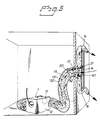
- the ventilation system shown in Fig. 1 comprises a portable unit 1 that includes a suction fan 11 for sucking-in fresh air from the outdoor surroundings and blowing the fresh air into a room, an extraction fan 12 for sucking-in foul air from said room and blowing the foul air into the outdoor atmosphere, and a flexible conduit 13 having two mutually separated passageways 131, 132 and means for connecting a respective passageway to the input side of the suction fan 11 and to the output side of the extraction fan 12.
- the conduit 13 can be compressed or squeezed transversely to its longitudinal direction so that a window through which the free end of the conduit is placed in communication with the outside atmosphere need only be opened to a slight extent in cold weather conditions, therewith greatly reducing the extent to which the room is cooled by fresh air entering through the window.
- the conduit 13 is constructed so that the fresh-air passageway 131 completely surrounds the foul-air passageway 132. This means that in wintertime, the cold fresh-air taken from the outdoor atmosphere will be heated by the hot foul air extracted from the room or space being ventilated. This effect can be accentuated still further, by dividing the two passageways 131, 132 of the conduit 13 into a number of concentrical sub-passageways that are arranged so that each alternate sub-passageway will be associated with one passageway 131 and each other alternate sub-passageway will be associated with the other passageway 132. Naturally, this will require the end piece of the conduit 13 located nearest the unit 1 to be correspondingly designed, so that sub-passageways belonging to a given passageway will mutually coact.
- a second flexible conduit 15 which is connected to the opening 17 of the portable unit 1 through which fresh air is blown out.
- This conduit can be given a considerable length, so that fresh air can be blown into the room at any desired location therein.
- Fig. 2 shows the free end of the air conduit 13 extended through an open window.
- the conduit is clamped between the partially open window and the window frame.
- the conduit is held firmly clamped to the window, in a slightly compressed state, with the aid of a clamping arrangement 21-20-22.
- the clamping arrangement is comprised of an outer clamp 21 which embraces the casement of the window, an inner plate 22 which is pressed firmly onto the window frame, and a rod 20 which connects the clamp 21 and the plate 22 and which is provided with a handle and forms means from which a hook 23 fixedly attached to the conduit 13 can be hung.
- the conduit 13 is compressed or squeezed together by pulling on the handle 201 and therewith securing the conduit to the window. Remaining parts of the window opening between the partially opened window and the window frame are conveniently sealed with the aid of pads 24, 25, 26, 27 made of a mechanically pliable, heat-insulating material.
- the passageways 131, 132 are constructed differently and connected so that fresh-air is now sucked-in through the inner passageway 131 and the foul air is blown out through the outer passageway 132.
- the pads 24-27 are replaced with two extension hoses 16. These hoses are attached so that air blown out from the passageway 132 passes through said hoses and out to the outdoor surroundings.
- the hoses 16 are placed in the window so as to substantially fill the gap presented by the partially open window, when inflated by the pressure from the fan 12.
- a window passage nozzle 14 includes rod 20 and hook 23 on which the conduit 13 is hung, and is tightened between the window casement and the window frame in the same manner as that described with reference to Fig. 2.
- the conduit 13 and the space-filling hoses 16 are connected (connectable) to the nozzle 14.
- the nozzle 14 is constructed so that the opening 141 for the suction passageway 131 widens towards the outdoor atmosphere, and the passageway 132 through which foul air is blown is divided into to two smaller sub-passageways which are connected to passageway openings 142.
- the space-filling hoses 16 are connected (connectable) to the outside of these openings.
Landscapes
- Engineering & Computer Science (AREA)
- Chemical & Material Sciences (AREA)
- Combustion & Propulsion (AREA)
- Mechanical Engineering (AREA)
- General Engineering & Computer Science (AREA)
- Jet Pumps And Other Pumps (AREA)
- Ventilation (AREA)
Applications Claiming Priority (2)
| Application Number | Priority Date | Filing Date | Title |
|---|---|---|---|
| SE9503840A SE509930C2 (sv) | 1995-10-31 | 1995-10-31 | Portabel ventilationsanordning |
| SE9503840 | 1995-10-31 |
Publications (3)
| Publication Number | Publication Date |
|---|---|
| EP0772008A2 true EP0772008A2 (de) | 1997-05-07 |
| EP0772008A3 EP0772008A3 (de) | 2000-03-08 |
| EP0772008B1 EP0772008B1 (de) | 2004-02-25 |
Family
ID=20400034
Family Applications (1)
| Application Number | Title | Priority Date | Filing Date |
|---|---|---|---|
| EP96850173A Expired - Lifetime EP0772008B1 (de) | 1995-10-31 | 1996-10-17 | Tragbares Belüftungssystem |
Country Status (5)
| Country | Link |
|---|---|
| US (1) | US5702296A (de) |
| EP (1) | EP0772008B1 (de) |
| CA (1) | CA2188986C (de) |
| DE (1) | DE69631631T2 (de) |
| SE (1) | SE509930C2 (de) |
Cited By (1)
| Publication number | Priority date | Publication date | Assignee | Title |
|---|---|---|---|---|
| KR101580509B1 (ko) * | 2014-09-19 | 2015-12-28 | 이성희 | 환풍기 |
Families Citing this family (19)
| Publication number | Priority date | Publication date | Assignee | Title |
|---|---|---|---|---|
| US6060689A (en) * | 1998-02-23 | 2000-05-09 | Wilson; Tim R. | Portable welding ventilation system |
| US6564512B1 (en) | 2001-01-26 | 2003-05-20 | Zipwall Llc | Mount for air moving device |
| US6702664B1 (en) * | 2001-10-16 | 2004-03-09 | Steven R. Coven | Portable fume exhauster-carpet and floor dryer |
| US20080039005A1 (en) * | 2002-10-10 | 2008-02-14 | Coven Steven R | Portable fume exhauster-carpet and floor dryer |
| US20040231181A1 (en) * | 2002-10-10 | 2004-11-25 | Coven Steven R. | Portable fume exhauster-carpet and floor dryer |
| US7094142B1 (en) * | 2003-02-25 | 2006-08-22 | Thomas Joseph Maskell | Portable device with interchangeable air cleaning modules for cleaning the air outside of an existing enclosed space and delivering the cleaned air into the existing enclosed space |
| US7624788B2 (en) * | 2004-04-22 | 2009-12-01 | State Of Oregon Acting By And Through The State Board Of Higher Education On Behalf Of The University Of Oregon | Heat exchanger |
| US20070235017A1 (en) * | 2006-04-05 | 2007-10-11 | Fitch John R | Portable heating apparatus |
| CN100392328C (zh) * | 2006-05-26 | 2008-06-04 | 金明吉 | 一种改进的新风换气机 |
| US8947249B1 (en) * | 2009-03-26 | 2015-02-03 | Safezone Safety Systems, LLC | Apparatus and method for conducting hot work |
| US8678889B2 (en) | 2009-09-02 | 2014-03-25 | Jerome Dean | Exhaust system |
| US8288326B2 (en) * | 2009-09-02 | 2012-10-16 | Chevron Oronite Company Llc | Natural gas engine lubricating oil compositions |
| TWI558954B (zh) * | 2014-09-22 | 2016-11-21 | 建準電機工業股份有限公司 | 具室內外溫差調節功能的氣流交換裝置 |
| US10436462B1 (en) * | 2015-10-19 | 2019-10-08 | Paul Baumgartner | Vent bypass system |
| US10823438B1 (en) * | 2019-09-05 | 2020-11-03 | Altapure, Llc | Vent bypass system |
| US10935276B2 (en) * | 2015-10-20 | 2021-03-02 | Steven Michalski | Air mixing device |
| US10518301B1 (en) | 2015-12-18 | 2019-12-31 | SafeZone Safety Systems, L.L.C. | Isolation enclosure and method for conducting hot work |
| CN110925929A (zh) * | 2018-09-19 | 2020-03-27 | 怡尔(北京)环境技术有限公司 | 一种可滤除pm2.5的分体新风机 |
| CN111842395A (zh) * | 2020-06-29 | 2020-10-30 | 鹤山市江磁线缆有限公司 | 一种油漆废气处理装置 |
Family Cites Families (13)
| Publication number | Priority date | Publication date | Assignee | Title |
|---|---|---|---|---|
| US558714A (en) * | 1896-04-21 | Electric heating | ||
| BE493374A (de) * | ||||
| US1800237A (en) * | 1928-05-25 | 1931-04-14 | Duplex Electric Company | Air-vent fan for vaults |
| US2091594A (en) * | 1935-08-27 | 1937-08-31 | James A Innes | Air conditioning apparatus for automobiles |
| FR2282090A1 (fr) * | 1974-08-14 | 1976-03-12 | Sharp Kk | Ventilateur-aerateur comprenant un echangeur de chaleur rotatif a regeneration |
| FR2344804A1 (fr) * | 1976-03-17 | 1977-10-14 | Fimec | Echangeur de recuperation thermique |
| SU981811A1 (ru) * | 1981-02-16 | 1982-12-15 | За витель B.C. Долгов / f | Теплообменник |
| CA1146357A (en) * | 1981-02-26 | 1983-05-17 | Norman Nathan | Mobile air conditioning unit |
| WO1983001500A1 (en) * | 1981-10-20 | 1983-04-28 | Bobjer, Olle | Ventilation method and apparatus |
| JPS60238631A (ja) * | 1984-05-12 | 1985-11-27 | Nippon Ranko Kk | 吸排気ダクト |
| GB2175082A (en) * | 1985-05-02 | 1986-11-19 | Wilhelm Anthony Andrew | Ventilation system |
| US4905579A (en) * | 1988-03-11 | 1990-03-06 | Dame Richard E | Radon gas ventilation pump system and method |
| US5000081A (en) * | 1990-04-23 | 1991-03-19 | Gilmer Robert S | Ventilation apparatus |
-
1995
- 1995-10-31 SE SE9503840A patent/SE509930C2/sv not_active IP Right Cessation
-
1996
- 1996-10-17 DE DE69631631T patent/DE69631631T2/de not_active Expired - Fee Related
- 1996-10-17 EP EP96850173A patent/EP0772008B1/de not_active Expired - Lifetime
- 1996-10-28 CA CA2188986A patent/CA2188986C/en not_active Expired - Fee Related
- 1996-10-30 US US08/739,195 patent/US5702296A/en not_active Expired - Fee Related
Non-Patent Citations (1)
| Title |
|---|
| None |
Cited By (1)
| Publication number | Priority date | Publication date | Assignee | Title |
|---|---|---|---|---|
| KR101580509B1 (ko) * | 2014-09-19 | 2015-12-28 | 이성희 | 환풍기 |
Also Published As
| Publication number | Publication date |
|---|---|
| DE69631631D1 (de) | 2004-04-01 |
| DE69631631T2 (de) | 2004-09-23 |
| EP0772008A3 (de) | 2000-03-08 |
| SE509930C2 (sv) | 1999-03-22 |
| CA2188986A1 (en) | 1997-05-01 |
| SE9503840D0 (sv) | 1995-10-31 |
| EP0772008B1 (de) | 2004-02-25 |
| CA2188986C (en) | 2006-01-24 |
| SE9503840L (sv) | 1997-05-01 |
| US5702296A (en) | 1997-12-30 |
Similar Documents
| Publication | Publication Date | Title |
|---|---|---|
| US5702296A (en) | Portable ventilation system | |
| WO2005040689A3 (en) | Window type air conditioner | |
| KR101470317B1 (ko) | 냉난방장치가 장착되는 옥외 부스 | |
| US3465539A (en) | Window air conditioner units | |
| US4497362A (en) | Regenerative room air exchanger | |
| CN210345814U (zh) | 一种适用于空调的挡风装置 | |
| CN220326357U (zh) | 一种通风效果好的通风系统 | |
| CN2387432Y (zh) | 带换气装置的空调器 | |
| CN2318549Y (zh) | 一种分离式窗式空调器 | |
| DE59710250D1 (de) | Lüftungssystem für die Räume von Gebäuden | |
| JP3702716B2 (ja) | 熱交換機ユニットの吹出装置 | |
| JPH11304187A (ja) | 空気調和システム | |
| JPS6222940A (ja) | 天井内設置型換気兼用冷暖房装置 | |
| JPS6341745A (ja) | 空気調和装置 | |
| RU1789726C (ru) | Устройство дл снижени воздухопроницаемости надшахтного здани | |
| JP3051143U (ja) | エアールーバー取り付け用のスポットフレキシブルホース | |
| JPH0350938B2 (de) | ||
| FI903138A7 (fi) | Luftvaexlingsanordning baserad pao principen om vaermetillvaratagande. | |
| JPH02178539A (ja) | 換気空調ユニット | |
| JPH01163545A (ja) | 空調換気装置 | |
| JPS61130743A (ja) | 台所の換気装置 | |
| JPH06307710A (ja) | 空調用吹出口装置 | |
| KR20070089004A (ko) | 폐열 회수 환기 에어컨 | |
| SK285417B6 (sk) | Vetracie zariadenie do interiérov | |
| JPH076682B2 (ja) | 窓面組込型分散ヒートポンプ空調機 |
Legal Events
| Date | Code | Title | Description |
|---|---|---|---|
| PUAI | Public reference made under article 153(3) epc to a published international application that has entered the european phase |
Free format text: ORIGINAL CODE: 0009012 |
|
| AK | Designated contracting states |
Kind code of ref document: A2 Designated state(s): CH DE DK FI LI NL |
|
| 17P | Request for examination filed |
Effective date: 19971014 |
|
| PUAL | Search report despatched |
Free format text: ORIGINAL CODE: 0009013 |
|
| AK | Designated contracting states |
Kind code of ref document: A3 Designated state(s): CH DE DK FI LI NL |
|
| RIC1 | Information provided on ipc code assigned before grant |
Free format text: 7F 24F 7/013 A, 7F 24F 1/04 B, 7F 24F 7/08 B, 7F 24F 12/00 B |
|
| 17Q | First examination report despatched |
Effective date: 20021025 |
|
| RAP1 | Party data changed (applicant data changed or rights of an application transferred) |
Owner name: WIND-BOX AB |
|
| GRAP | Despatch of communication of intention to grant a patent |
Free format text: ORIGINAL CODE: EPIDOSNIGR1 |
|
| GRAS | Grant fee paid |
Free format text: ORIGINAL CODE: EPIDOSNIGR3 |
|
| GRAA | (expected) grant |
Free format text: ORIGINAL CODE: 0009210 |
|
| RAP1 | Party data changed (applicant data changed or rights of an application transferred) |
Owner name: WIND-BOX AB |
|
| AK | Designated contracting states |
Kind code of ref document: B1 Designated state(s): CH DE DK FI LI NL |
|
| PG25 | Lapsed in a contracting state [announced via postgrant information from national office to epo] |
Ref country code: NL Free format text: LAPSE BECAUSE OF FAILURE TO SUBMIT A TRANSLATION OF THE DESCRIPTION OR TO PAY THE FEE WITHIN THE PRESCRIBED TIME-LIMIT Effective date: 20040225 Ref country code: LI Free format text: LAPSE BECAUSE OF FAILURE TO SUBMIT A TRANSLATION OF THE DESCRIPTION OR TO PAY THE FEE WITHIN THE PRESCRIBED TIME-LIMIT Effective date: 20040225 Ref country code: FI Free format text: LAPSE BECAUSE OF FAILURE TO SUBMIT A TRANSLATION OF THE DESCRIPTION OR TO PAY THE FEE WITHIN THE PRESCRIBED TIME-LIMIT Effective date: 20040225 Ref country code: CH Free format text: LAPSE BECAUSE OF FAILURE TO SUBMIT A TRANSLATION OF THE DESCRIPTION OR TO PAY THE FEE WITHIN THE PRESCRIBED TIME-LIMIT Effective date: 20040225 |
|
| REG | Reference to a national code |
Ref country code: CH Ref legal event code: EP |
|
| REF | Corresponds to: |
Ref document number: 69631631 Country of ref document: DE Date of ref document: 20040401 Kind code of ref document: P |
|
| PG25 | Lapsed in a contracting state [announced via postgrant information from national office to epo] |
Ref country code: DK Free format text: LAPSE BECAUSE OF FAILURE TO SUBMIT A TRANSLATION OF THE DESCRIPTION OR TO PAY THE FEE WITHIN THE PRESCRIBED TIME-LIMIT Effective date: 20040525 |
|
| NLV1 | Nl: lapsed or annulled due to failure to fulfill the requirements of art. 29p and 29m of the patents act | ||
| REG | Reference to a national code |
Ref country code: CH Ref legal event code: PL |
|
| PLBE | No opposition filed within time limit |
Free format text: ORIGINAL CODE: 0009261 |
|
| STAA | Information on the status of an ep patent application or granted ep patent |
Free format text: STATUS: NO OPPOSITION FILED WITHIN TIME LIMIT |
|
| 26N | No opposition filed |
Effective date: 20041126 |
|
| PGFP | Annual fee paid to national office [announced via postgrant information from national office to epo] |
Ref country code: DE Payment date: 20081022 Year of fee payment: 13 |
|
| PG25 | Lapsed in a contracting state [announced via postgrant information from national office to epo] |
Ref country code: DE Free format text: LAPSE BECAUSE OF NON-PAYMENT OF DUE FEES Effective date: 20100501 |