EP0772018A2 - Echangeur de chaleur pour le refroidissement de gaz d'échappement - Google Patents
Echangeur de chaleur pour le refroidissement de gaz d'échappement Download PDFInfo
- Publication number
- EP0772018A2 EP0772018A2 EP96115729A EP96115729A EP0772018A2 EP 0772018 A2 EP0772018 A2 EP 0772018A2 EP 96115729 A EP96115729 A EP 96115729A EP 96115729 A EP96115729 A EP 96115729A EP 0772018 A2 EP0772018 A2 EP 0772018A2
- Authority
- EP
- European Patent Office
- Prior art keywords
- heat exchanger
- exchanger according
- sheet metal
- welded
- metal jacket
- Prior art date
- Legal status (The legal status is an assumption and is not a legal conclusion. Google has not performed a legal analysis and makes no representation as to the accuracy of the status listed.)
- Granted
Links
- 238000001816 cooling Methods 0.000 title claims description 3
- 239000002826 coolant Substances 0.000 claims abstract description 28
- 239000002184 metal Substances 0.000 claims description 43
- XLYOFNOQVPJJNP-UHFFFAOYSA-N water Substances O XLYOFNOQVPJJNP-UHFFFAOYSA-N 0.000 claims description 5
- 125000006850 spacer group Chemical group 0.000 claims description 4
- 238000002485 combustion reaction Methods 0.000 claims description 2
- 239000007788 liquid Substances 0.000 claims description 2
- 239000000463 material Substances 0.000 claims 1
- 238000003466 welding Methods 0.000 description 19
- 238000000034 method Methods 0.000 description 5
- 229910000831 Steel Inorganic materials 0.000 description 4
- 239000010959 steel Substances 0.000 description 4
- 238000007789 sealing Methods 0.000 description 3
- 238000013459 approach Methods 0.000 description 1
- 230000015572 biosynthetic process Effects 0.000 description 1
- 230000003197 catalytic effect Effects 0.000 description 1
- 230000006835 compression Effects 0.000 description 1
- 238000007906 compression Methods 0.000 description 1
- 238000004519 manufacturing process Methods 0.000 description 1
Images

Classifications
-
- F—MECHANICAL ENGINEERING; LIGHTING; HEATING; WEAPONS; BLASTING
- F28—HEAT EXCHANGE IN GENERAL
- F28F—DETAILS OF HEAT-EXCHANGE AND HEAT-TRANSFER APPARATUS, OF GENERAL APPLICATION
- F28F1/00—Tubular elements; Assemblies of tubular elements
- F28F1/02—Tubular elements of cross-section which is non-circular
- F28F1/04—Tubular elements of cross-section which is non-circular polygonal, e.g. rectangular
-
- F—MECHANICAL ENGINEERING; LIGHTING; HEATING; WEAPONS; BLASTING
- F28—HEAT EXCHANGE IN GENERAL
- F28D—HEAT-EXCHANGE APPARATUS, NOT PROVIDED FOR IN ANOTHER SUBCLASS, IN WHICH THE HEAT-EXCHANGE MEDIA DO NOT COME INTO DIRECT CONTACT
- F28D7/00—Heat-exchange apparatus having stationary tubular conduit assemblies for both heat-exchange media, the media being in contact with different sides of a conduit wall
- F28D7/16—Heat-exchange apparatus having stationary tubular conduit assemblies for both heat-exchange media, the media being in contact with different sides of a conduit wall the conduits being arranged in parallel spaced relation
- F28D7/1684—Heat-exchange apparatus having stationary tubular conduit assemblies for both heat-exchange media, the media being in contact with different sides of a conduit wall the conduits being arranged in parallel spaced relation the conduits having a non-circular cross-section
-
- F—MECHANICAL ENGINEERING; LIGHTING; HEATING; WEAPONS; BLASTING
- F28—HEAT EXCHANGE IN GENERAL
- F28D—HEAT-EXCHANGE APPARATUS, NOT PROVIDED FOR IN ANOTHER SUBCLASS, IN WHICH THE HEAT-EXCHANGE MEDIA DO NOT COME INTO DIRECT CONTACT
- F28D9/00—Heat-exchange apparatus having stationary plate-like or laminated conduit assemblies for both heat-exchange media, the media being in contact with different sides of a conduit wall
- F28D9/0031—Heat-exchange apparatus having stationary plate-like or laminated conduit assemblies for both heat-exchange media, the media being in contact with different sides of a conduit wall the conduits for one heat-exchange medium being formed by paired plates touching each other
-
- F—MECHANICAL ENGINEERING; LIGHTING; HEATING; WEAPONS; BLASTING
- F28—HEAT EXCHANGE IN GENERAL
- F28F—DETAILS OF HEAT-EXCHANGE AND HEAT-TRANSFER APPARATUS, OF GENERAL APPLICATION
- F28F13/00—Arrangements for modifying heat-transfer, e.g. increasing, decreasing
- F28F13/06—Arrangements for modifying heat-transfer, e.g. increasing, decreasing by affecting the pattern of flow of the heat-exchange media
- F28F13/12—Arrangements for modifying heat-transfer, e.g. increasing, decreasing by affecting the pattern of flow of the heat-exchange media by creating turbulence, e.g. by stirring, by increasing the force of circulation
-
- F—MECHANICAL ENGINEERING; LIGHTING; HEATING; WEAPONS; BLASTING
- F28—HEAT EXCHANGE IN GENERAL
- F28F—DETAILS OF HEAT-EXCHANGE AND HEAT-TRANSFER APPARATUS, OF GENERAL APPLICATION
- F28F9/00—Casings; Header boxes; Auxiliary supports for elements; Auxiliary members within casings
-
- F—MECHANICAL ENGINEERING; LIGHTING; HEATING; WEAPONS; BLASTING
- F28—HEAT EXCHANGE IN GENERAL
- F28F—DETAILS OF HEAT-EXCHANGE AND HEAT-TRANSFER APPARATUS, OF GENERAL APPLICATION
- F28F9/00—Casings; Header boxes; Auxiliary supports for elements; Auxiliary members within casings
- F28F9/02—Header boxes; End plates
- F28F9/0246—Arrangements for connecting header boxes with flow lines
-
- F—MECHANICAL ENGINEERING; LIGHTING; HEATING; WEAPONS; BLASTING
- F28—HEAT EXCHANGE IN GENERAL
- F28D—HEAT-EXCHANGE APPARATUS, NOT PROVIDED FOR IN ANOTHER SUBCLASS, IN WHICH THE HEAT-EXCHANGE MEDIA DO NOT COME INTO DIRECT CONTACT
- F28D21/00—Heat-exchange apparatus not covered by any of the groups F28D1/00 - F28D20/00
- F28D21/0001—Recuperative heat exchangers
- F28D21/0003—Recuperative heat exchangers the heat being recuperated from exhaust gases
-
- Y—GENERAL TAGGING OF NEW TECHNOLOGICAL DEVELOPMENTS; GENERAL TAGGING OF CROSS-SECTIONAL TECHNOLOGIES SPANNING OVER SEVERAL SECTIONS OF THE IPC; TECHNICAL SUBJECTS COVERED BY FORMER USPC CROSS-REFERENCE ART COLLECTIONS [XRACs] AND DIGESTS
- Y10—TECHNICAL SUBJECTS COVERED BY FORMER USPC
- Y10T—TECHNICAL SUBJECTS COVERED BY FORMER US CLASSIFICATION
- Y10T29/00—Metal working
- Y10T29/49—Method of mechanical manufacture
- Y10T29/4935—Heat exchanger or boiler making
- Y10T29/49373—Tube joint and tube plate structure
-
- Y—GENERAL TAGGING OF NEW TECHNOLOGICAL DEVELOPMENTS; GENERAL TAGGING OF CROSS-SECTIONAL TECHNOLOGIES SPANNING OVER SEVERAL SECTIONS OF THE IPC; TECHNICAL SUBJECTS COVERED BY FORMER USPC CROSS-REFERENCE ART COLLECTIONS [XRACs] AND DIGESTS
- Y10—TECHNICAL SUBJECTS COVERED BY FORMER USPC
- Y10T—TECHNICAL SUBJECTS COVERED BY FORMER US CLASSIFICATION
- Y10T29/00—Metal working
- Y10T29/49—Method of mechanical manufacture
- Y10T29/4935—Heat exchanger or boiler making
- Y10T29/49391—Tube making or reforming
Definitions
- the invention relates to a heat exchanger for cooling exhaust gas from an internal combustion engine with a plurality of channels for guiding the exhaust gas, which are provided with tabs arranged in pairs at an angle to the flow direction, projecting from at least one wall of the channels, and a liquid cooling medium flows around the outside.
- the channels are formed from disk-shaped heat exchange elements, between each of which a turbulence insert is arranged, which has the tabs arranged in pairs at an angle to the flow direction.
- This heat exchanger known from DE-U 94 06 197.1 fulfills the task placed on it in a satisfactory manner.
- the invention has for its object to provide a heat exchanger of the type mentioned, which can be produced in different sizes with essentially the same structure is, with not too high dimensional tolerances have to be maintained for the individual components.
- a bundle of rectangular tubes is provided as channels for the exhaust gas, the ends of which are welded into grid-shaped tube sheets, that the bundle of rectangular tubes is surrounded by a sheet metal jacket which follows the contour of the bundle which enters with a cooling medium and is provided with a cooling medium outlet and which is welded to the tube sheets, and that the ends of the sheet metal jacket are provided with welded-on flange plates, each of which is open to the bundle of rectangular tubes by means of a central opening and which are provided with fastening means for fastening to tube pieces of an exhaust pipe .
- the welded heat exchanger according to the invention essentially consists of sheet metal components that can be manufactured in a simple manner.
- the welding is preferably carried out as laser welding or micro TIG welding.
- the grid-shaped tube sheets which are stamped from sheet steel of approximately 1 mm to 3 mm in thickness, have openings in accordance with the number and arrangement of the rectangular tubes.
- the distances between the rectangular tubes and thus the web width of the tube base varies depending on the mass flow of the coolant and is also on the order of 1 mm to 3 mm.
- the outer contour of the tube sheets results from the number and arrangement of the flat tubes.
- the sheet metal jacket is also produced in a simple manner from a steel sheet which has a sheet thickness similar to that of the tube sheets.
- the sheet metal jacket can be folded in steps according to the contour of the tube sheets in a simple manner.
- the flange plates provided with fastening means allow the heat exchanger to be arranged in a simple manner between two pipe sections of an exhaust pipe, for example in a manner similar to the arrangement of a catalytic converter.
- the rectangular tubes are each formed from two tube shells welded together.
- the pair of tabs can be attached directly to the rectangular tube or be part of this rectangular tube. However, they can also be part of inserts arranged in the rectangular tubes.
- the flange plates are provided with threaded sleeves in essentially diametrically opposite areas. A screw connection with a counter flange of a pipe section of an exhaust pipe is thereby possible in a simple manner.
- the sheet metal jacket is provided with a cooling medium inlet in the vicinity of the front flange plate in the flow direction of the exhaust gas and with a cooling medium outlet in the vicinity of the rear flange plate. This initially ensures that the cooling medium is passed in direct current to the exhaust gas through the heat exchanger. This ensures that the risk of steam formation on the inlet side of the exhaust gas is reduced since the cooling medium has the relatively lowest temperature here.
- the cooling medium inlet and the cooling medium outlet are arranged on opposite sides of the sheet metal jacket. Because of this arrangement, the flow paths of the individual flow paths for the cooling medium around the rectangular tubes are essentially of the same length, so that a uniform flow around these rectangular tubes is ensured.
- the sheet metal jacket is composed of two preformed sheet metal shells which are joined to the tube sheets by means of joint connections connect. After welding, the two sheet metal shells result in a rigid and pressure-resistant housing.
- the provision of joint connections has the advantage that the elements to be welded have a certain degree of cohesion before welding, so that the welding process can be carried out relatively easily.
- the flange plates connect to the sheet metal jacket by means of joint connections. It is also provided for the same purpose that the threaded sleeves connect to the flange plates by means of a joint connection. The welding process can thus be carried out relatively easily.
- the heat exchanger shown in Figures 1 and 2 has a bundle of flat tubes (10) which have a wall thickness in the area have from 0.3mm to 0.4mm.
- the ends of the rectangular tubes (10) are inserted into the tubular tube plates (11) and welded to them.
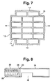
- Such a tube sheet (11), which serves to hold 16 rectangular tubes, is shown in FIG. 7, for example.
- These tube sheets (11) are punched from a steel sheet which has a sheet thickness in the order of 1 mm to 3 mm.
- the webs between the openings which serve to receive the flat tubes have a width which corresponds approximately to the wall thickness of the rectangular tubes (10).
- the arrangement of the openings and thus the webs of the tube sheets (11) is selected so that a circular or oval cross section is obtained in rough approximation.
- the webs comprising the external rectangular tubes also have the same web width, so that the outer contour of the tube sheets corresponds to the contour of the tube bundle - increased by the web width.
- the tube sheets (11) are welded into the ends of a sheet metal jacket (12), which is also indicated by dashed lines in FIG. 7.
- the sheet metal jacket (12) consists of two half-shells made of sheet steel, which has a thickness which essentially corresponds to the thickness of the tube sheets (11).
- the half-shells are shaped according to the outer contour of the tube sheets (11), for example edged or by means of a high-pressure forming process.
- the two half-shells of the sheet metal jacket (12) are connected to one another by means of longitudinal weld seams (13).
- the tube sheets (11) are provided with a total of four somewhat widened lugs (14), which are assigned corresponding recesses at the end of the two half-shells of the sheet metal jacket (12), so that a joint connection is hereby created.
- Flange plates (15) are welded to the two ends of the sheet metal jacket (12), which are also stamped from sheet metal and have a sheet thickness similar to the sheet thickness of the tube sheets (11).
- the flange plates (15) are in two diametrically opposite areas laterally over the contour of the Sheet metal over. In this area, the sheet metal jacket (12) is extended in the axial direction beyond the tube sheets (11) and inserted with these extended approaches into slot-shaped recesses (17) in the flange sheets (15). In this area, welding takes place from the outside of the flange plates (15), while in the remaining area, welding is provided from the other side.
- the flange plates (15) have a central, preferably circular recess (18), the dimensions of which correspond to the preceding and following pipe sections, not shown, of an exhaust system or exhaust system of a vehicle.
- the flange plates (15) are provided with threaded sleeves (19, 20) in the diametrically opposite regions which project outwardly beyond the sheet metal jacket (12).
- the threaded sleeves (19) are inserted with an annular collar located on their open side into bores in the flange plates (15) and welded to them from the respective outside of the flange plates (15).
- the threaded sleeves (19) In the area of their closed side, the threaded sleeves (19) have an annular collar with which they are inserted into a retaining web (21). This retaining web (21) is welded to the threaded sleeves (19) and the sheet metal jacket (12).
- the connecting pipe (24) and the threaded sleeve (20) are each welded to one another with a weld seam (25).
- the outside of the weld seam (25) is ground off.
- a lateral recess (26) is then milled into the connecting pipe (24).
- the threaded sleeves (20) are welded with their ring collar (23) into recesses in the flange plates (15) and with welded the flange plates (15).
- the connecting pipes (24) are additionally welded to the sheet metal jacket by means of retaining webs (27).
- the respective outer edges of the holding webs (27) run tangentially to the connecting pipe (24) to a flat surface of the sheet metal jacket. They are covered by welded cover plates (28) which are welded to the sheet metal jacket (12), the retaining webs (27), the connecting pipe (24), the threaded sleeves (20) and the flange plate (15).
- a kind of water box is thus formed in the area of the cutouts (26) between the holding webs (27) and the flange sheets (15), in the area of which the sheet metal jacket is provided with an inlet opening.
- the connecting pipes (24) and the associated water boxes are on opposite sides of the sheet metal jacket, so that an approximately Z-shaped flow path is created for the cooling medium indicated by the arrows (29).
- This flow path has approximately the same flow path in the area of all rectangular tubes (10), so that there is a very good and uniform flow around the rectangular tubes (10).
- the coolant inlet in FIG. 1 above is arranged on the side on which the exhaust gas indicated by the arrow (30) is also located, while the coolant outlet is located on the side indicated by the arrow ( 31) indicated outlet side of the exhaust gas. The cooling medium and the exhaust gas thus flow in cocurrent within the heat exchanger.
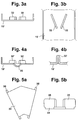
- the rectangular tubes are provided with tabs (32) which are arranged in pairs and project inwardly from opposite walls and which are arranged obliquely to the flow direction of the exhaust gas that they diverge from a narrowest point at an angle of about 40 °.
- the rectangular tubes are each welded together from two tube shells (10 ') which are welded together on their narrow sides.
- the pipe shells have a sheet thickness of about 0.3mm to 0.4mm.
- the tabs (32) have approximately the same thickness and a length of about ten times their sheet thickness. They diverge from a narrowest point at which they are about 1.2 mm apart at an angle of 40 °.
- the height of the tabs (32) is about a quarter to a third of the total height of the flat tubes.
- the tube halves (10 ') are provided with slots into which the tabs (32) are inserted and then welded to the tube halves (10').
- the tabs (32) can be provided on their side facing the tube halves (10 ') with one or more elevations, so that they are welded to the tube halves (10') using the known stud welding technique, so that the Tight welding is not necessary.
- the tabs (32) of the two tube halves are arranged opposite one another.
- the tabs (32) of the two tube halves (10 ') are arranged off-center such that the tabs (32) of the upper tube half and the lower tube half (10') are offset in the transverse direction to one another.
- the distance between the tabs (32) in the flow direction of the exhaust gas is approximately 30 mm.
- the tabs (32 ') are each formed out of the tube half (10') by deep drawing and compression. This eliminates the need for a welding process, particularly sealing welding in the area of the tabs (32 ').
- Fig. 4a it is further shown that the tube half (10 ') is provided with an outward button-like shape (33).
- a component which is a folded sheet metal part (34) which forms pairs of tabs (35).
- This component (34) can be attached to the tube halves (10 ') in the region of the web connecting the tabs (35) by means of spot welding. This also eliminates sealing welding.
- the web of the component (34) connecting the tabs (35) is provided with tabs bent to the opposite side, which are inserted and welded into slots in the tube half (10 ') and which protrude outwards to form spacers to the adjacent rectangular tubes (10).
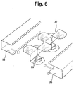
- FIG. 6 shows an exemplary embodiment of rectangular tubes which are formed from two tube halves (36) divided in the longitudinal direction in the region of the larger walls.
- a sheet (37) is inserted into the two tube halves (36), which is deformed into S-shaped and Z-shaped, successive sections.
- the parts running parallel to the longer walls of the tube half (36) are provided with pairs of tabs (38) which are arranged and designed in accordance with the explanations for FIGS. 3a and 3b.
- the tube halves (36) are connected to one another by laser welding or micro TIG welding, the inserted sheet metal (37) being fixed with the aid of a through-welding.
- the tube halves (10 ') are first provided with the tabs (32, 32', 35 or 38) and then welded together.
- the rectangular tubes thus formed are provided with the tube sheets (11) punched out in a lattice shape, after which the ends of the rectangular tubes (10) are welded to the tube sheets.
- the two profiled sheet metal shells of the sheet metal jacket (12) the ones with prepared inlet openings and outlet openings are provided for the cooling medium, attached to the tube sheets (11) and welded to them.
- the flange plates (15) are then attached and welded to the sheet metal jacket (12).
- the prepared threaded sleeves (19, 20) are then attached to the flange sheets and welded to them, and welded to the sheet metal jacket (12) by means of the holding webs (21, 27). Then the cover plates (28) are attached, which are welded to the retaining webs (27), the sheet metal jacket (12), the connecting pipes (24), the threaded sleeves (20) and the flange plates (15) in such a way that a type of water tank is formed.
Landscapes
- Engineering & Computer Science (AREA)
- Physics & Mathematics (AREA)
- Thermal Sciences (AREA)
- Mechanical Engineering (AREA)
- General Engineering & Computer Science (AREA)
- Geometry (AREA)
- Heat-Exchange Devices With Radiators And Conduit Assemblies (AREA)
- Exhaust Silencers (AREA)
Applications Claiming Priority (2)
| Application Number | Priority Date | Filing Date | Title |
|---|---|---|---|
| DE19540683A DE19540683A1 (de) | 1995-11-01 | 1995-11-01 | Wärmeüberträger zum Kühlen von Abgas |
| DE19540683 | 1995-11-01 |
Publications (3)
| Publication Number | Publication Date |
|---|---|
| EP0772018A2 true EP0772018A2 (fr) | 1997-05-07 |
| EP0772018A3 EP0772018A3 (fr) | 1998-07-29 |
| EP0772018B1 EP0772018B1 (fr) | 2001-02-28 |
Family
ID=7776346
Family Applications (1)
| Application Number | Title | Priority Date | Filing Date |
|---|---|---|---|
| EP96115729A Expired - Lifetime EP0772018B1 (fr) | 1995-11-01 | 1996-10-01 | Echangeur de chaleur pour le refroidissement de gaz d'échappement |
Country Status (6)
| Country | Link |
|---|---|
| US (2) | US6944947B1 (fr) |
| EP (1) | EP0772018B1 (fr) |
| JP (1) | JP3429143B2 (fr) |
| BR (1) | BR9605398A (fr) |
| DE (2) | DE19540683A1 (fr) |
| ES (1) | ES2154375T3 (fr) |
Cited By (3)
| Publication number | Priority date | Publication date | Assignee | Title |
|---|---|---|---|---|
| EP0851200A3 (fr) * | 1996-12-24 | 1999-05-12 | Behr GmbH & Co. | Procédé pour la réalisation de languettes et/ou de saillies sur une tÔle mince et tube en tÔle mince à section rectangulaire |
| EP0851197A3 (fr) * | 1996-12-24 | 1999-05-19 | Behr GmbH & Co. | Echangeur de chaleur, en particulier pour gaz d'échappement |
| US7559197B2 (en) | 2005-08-31 | 2009-07-14 | Caterpillar Inc. | Combiner valve control system and method |
Families Citing this family (34)
| Publication number | Priority date | Publication date | Assignee | Title |
|---|---|---|---|---|
| DE19654366B4 (de) * | 1996-12-24 | 2005-10-20 | Behr Gmbh & Co Kg | Strömungskanal, insbesondere für einen Abgaswärmeübertrager |
| DE19654364B4 (de) * | 1996-12-24 | 2007-05-16 | Behr Gmbh & Co Kg | Strömungskanal, insbesondere für einen Gas-Flüssigkeit-Wärmeübertrager |
| DE19654363B4 (de) * | 1996-12-24 | 2007-09-27 | Behr Gmbh & Co. Kg | Abgaswärmeübertrager für einen Verbrennungsmotor |
| JP4130512B2 (ja) | 1998-04-24 | 2008-08-06 | ベール ゲゼルシャフト ミット ベシュレンクテル ハフツング ウント コンパニー | 熱交換器 |
| DE19907163C2 (de) * | 1998-04-24 | 2003-08-14 | Behr Gmbh & Co | Wärmetauscher, insbesondere Abgaswärmetauscher |
| DE19955939A1 (de) | 1999-11-20 | 2001-05-23 | Volkswagen Ag | Wärmetauscher zur Kühlung von Abgasen und ein Verfahren zur Herstellung eines Rohrs für einen Wärmetauscher |
| DE19962863B4 (de) * | 1999-12-24 | 2013-09-19 | Behr Gmbh & Co. Kg | Wärmeübertrager |
| DE10127084B4 (de) * | 2000-06-17 | 2019-05-29 | Mahle International Gmbh | Wärmeübertrager, insbesondere für Kraftfahrzeuge |
| DE10162198A1 (de) | 2000-12-19 | 2002-08-08 | Denso Corp | Wärmetauscher |
| JP3774843B2 (ja) | 2001-05-25 | 2006-05-17 | マルヤス工業株式会社 | 多管式熱交換器 |
| US7077190B2 (en) | 2001-07-10 | 2006-07-18 | Denso Corporation | Exhaust gas heat exchanger |
| KR100932677B1 (ko) * | 2001-08-10 | 2009-12-22 | 요코하마 티엘오 가부시키가이샤 | 열전달 장치 |
| DE10144827A1 (de) * | 2001-09-12 | 2003-03-27 | Behr Gmbh & Co | Abgaswärmeübertrager |
| ITMI20030363A1 (it) * | 2003-02-28 | 2004-09-01 | Lorenzo Bormioli | Dispositivo a comando remoto per l'aggancio e sgancio rapido di un raccordo per tubazioni ad una tubazione flangiata. |
| DE10311716A1 (de) | 2003-03-17 | 2004-10-14 | Evotec Oai Ag | Verfahren und Vorrichtung zur Trennung von Partikeln in einer Flüssigkeitsströmung |
| DE10328638A1 (de) | 2003-06-26 | 2005-01-20 | Modine Manufacturing Co., Racine | Wärmetauscher in gehäuseloser Plattenbauweise |
| JP2007506020A (ja) | 2003-09-18 | 2007-03-15 | ベール ゲーエムベーハー ウント コー カーゲー | 排ガス熱伝達体、特に自動車内の排ガス還流用の排ガスクーラー |
| CA2443496C (fr) | 2003-09-30 | 2011-10-11 | Dana Canada Corporation | Echangeurs de chaleur a faisceau comprenant des tubes a extremite de section elargie |
| EP2267393B1 (fr) * | 2003-10-28 | 2017-06-28 | MAHLE Behr GmbH & Co. KG | Canal d'écoulement pour un échangeur de chaleur |
| JP4614266B2 (ja) * | 2004-07-23 | 2011-01-19 | 臼井国際産業株式会社 | 流体攪拌用フィン並びに該フィンを内装した伝熱管および熱交換器または熱交換型ガス冷却装置 |
| WO2006100072A1 (fr) | 2005-03-24 | 2006-09-28 | Behr Gmbh & Co. Kg | Echangeur thermique pour gaz d'echappement, notamment refroidisseur de gaz d'echappement pour le recyclage des gaz d'echappement dans les vehicules a moteur |
| DE102005014385A1 (de) * | 2005-03-24 | 2006-09-28 | Emitec Gesellschaft Für Emissionstechnologie Mbh | Abgaswärmeübertrager, insbesondere Abgaskühler für Abgasrückführung in Kraftfahrzeugen |
| DE102005029321A1 (de) | 2005-06-24 | 2006-12-28 | Behr Gmbh & Co. Kg | Wärmeübertrager |
| CN101398274B (zh) * | 2007-09-29 | 2012-07-25 | 卡特彼勒公司 | 经激光焊接的热交换器管组件 |
| US8177932B2 (en) * | 2009-02-27 | 2012-05-15 | International Mezzo Technologies, Inc. | Method for manufacturing a micro tube heat exchanger |
| IT1399246B1 (it) | 2009-11-03 | 2013-04-11 | Advanced Res Consulting S R L | Scambiatore di calore tubolare, in particolare tubo ricevitore per un impianto solare a concentrazione. |
| CA2964399C (fr) * | 2016-04-12 | 2025-08-26 | 6353908 Canada Inc. | Conduit d'echangeur thermique et echangeur thermique |
| US20220069663A1 (en) * | 2019-01-10 | 2022-03-03 | Mitsubishi Heavy Industries Engine & Turbocharger, Ltd. | Motor, and inverter-integrated rotating electric machine |
| US11566855B2 (en) * | 2019-08-09 | 2023-01-31 | Mikutay Corporation | Tube and chamber heat exchange apparatus having a medium directing assembly with enhanced medium directing panels |
| FR3105649B1 (fr) * | 2019-12-19 | 2021-11-26 | Valeo Equip Electr Moteur | Machine électrique tournante refroidie |
| US11639828B2 (en) * | 2020-06-25 | 2023-05-02 | Turbine Aeronautics IP Pty Ltd | Heat exchanger |
| CN114172307A (zh) * | 2020-09-11 | 2022-03-11 | 法雷奥动力总成(上海)有限公司 | 旋转电机、动力传动系统和电动车 |
| JP7509048B2 (ja) * | 2021-02-02 | 2024-07-02 | トヨタ自動車株式会社 | 電動車両 |
| US12323025B2 (en) * | 2022-10-24 | 2025-06-03 | Schaeffler Technologies AG & Co. KG | Heat exchanger system for an electric motor with fluid circuits arranged between shafts |
Citations (1)
| Publication number | Priority date | Publication date | Assignee | Title |
|---|---|---|---|---|
| DE9406197U1 (de) | 1994-04-14 | 1994-06-16 | Behr Gmbh & Co | Wärmetauscher zum Kühlen von Abgas eines Kraftfahrzeugmotors |
Family Cites Families (22)
| Publication number | Priority date | Publication date | Assignee | Title |
|---|---|---|---|---|
| DE269073C (fr) | ||||
| US709416A (en) * | 1901-03-28 | 1902-09-16 | Daimler Mfg Company | Cooling and condensing apparatus. |
| FR6582E (fr) * | 1906-03-31 | 1907-01-07 | Emile Chopy | Tubes pour radiateurs d'automobiles |
| US1182271A (en) * | 1914-09-19 | 1916-05-09 | Harvey E Hersh | Process of making radiators. |
| US2488615A (en) * | 1942-11-11 | 1949-11-22 | Modine Mfg Co | Oil cooler tube |
| US2941787A (en) * | 1956-04-13 | 1960-06-21 | Pedar Ltd | Apparatus for heat exchange |
| DE2102744A1 (en) * | 1971-01-21 | 1972-08-03 | Fritz Voltz Sohn | Heat exchanger - with flattened oval heat transfer tubes |
| US3757855A (en) * | 1971-10-15 | 1973-09-11 | Union Carbide Corp | Primary surface heat exchanger |
| US4262659A (en) * | 1980-01-24 | 1981-04-21 | Valley Industries, Inc. | Solar radiation absorbing panel |
| ZA818455B (en) * | 1980-12-09 | 1982-10-27 | Racecourse Co Operative Ass Lt | Heat exchanger and apparatus including same |
| US4546825A (en) * | 1983-01-28 | 1985-10-15 | Mccord Heat Transfer Corporation | Heat exchanger and method of assembly thereof |
| FR2575279B1 (fr) * | 1984-12-21 | 1989-07-07 | Barriquand | Echangeur a plaques |
| US4681155A (en) * | 1986-05-01 | 1987-07-21 | The Garrett Corporation | Lightweight, compact heat exchanger |
| DE3636762C1 (de) * | 1986-10-29 | 1988-03-03 | Mtu Muenchen Gmbh | Waermetauscher |
| DD269073A3 (de) * | 1987-04-23 | 1989-06-21 | Energie & Transportforsch Inst | Wirbelbleche fuer waermeuebertrager |
| GB8823229D0 (en) * | 1988-10-04 | 1988-11-09 | Pyroban Ltd | Heat exchanger |
| US4971137A (en) * | 1989-11-09 | 1990-11-20 | American Energy Exchange, Inc. | Air-to-air heat exchanger with frost preventing means |
| DE4035896C1 (en) * | 1990-11-12 | 1992-01-30 | Hampel, Heinrich, Dr., Moresnet, Be | Cooling box for blast furnace - comprising base and cover plates with side walls, and spacers to form long cooling channel |
| US5038754A (en) * | 1991-01-28 | 1991-08-13 | Scala Neal S | Fireplace heat exchanger |
| DE4141556C2 (de) * | 1991-12-17 | 2003-01-30 | Behr Gmbh & Co | Wärmetauscher für eine Abgasanlage eines Kraftfahrzeuges |
| US5251693A (en) * | 1992-10-19 | 1993-10-12 | Zifferer Lothar R | Tube-in-shell heat exchanger with linearly corrugated tubing |
| DE19654368B4 (de) * | 1996-12-24 | 2006-01-05 | Behr Gmbh & Co. Kg | Wärmeübertrager, insbesondere Abgaswärmeübertrager |
-
1995
- 1995-11-01 DE DE19540683A patent/DE19540683A1/de not_active Withdrawn
-
1996
- 1996-10-01 ES ES96115729T patent/ES2154375T3/es not_active Expired - Lifetime
- 1996-10-01 EP EP96115729A patent/EP0772018B1/fr not_active Expired - Lifetime
- 1996-10-01 DE DE59606495T patent/DE59606495D1/de not_active Expired - Lifetime
- 1996-10-28 JP JP28500396A patent/JP3429143B2/ja not_active Expired - Fee Related
- 1996-10-31 BR BR9605398A patent/BR9605398A/pt not_active IP Right Cessation
- 1996-11-01 US US08/743,002 patent/US6944947B1/en not_active Expired - Fee Related
-
2005
- 2005-04-29 US US11/117,503 patent/US7246437B2/en not_active Expired - Fee Related
Patent Citations (1)
| Publication number | Priority date | Publication date | Assignee | Title |
|---|---|---|---|---|
| DE9406197U1 (de) | 1994-04-14 | 1994-06-16 | Behr Gmbh & Co | Wärmetauscher zum Kühlen von Abgas eines Kraftfahrzeugmotors |
Cited By (4)
| Publication number | Priority date | Publication date | Assignee | Title |
|---|---|---|---|---|
| EP0851200A3 (fr) * | 1996-12-24 | 1999-05-12 | Behr GmbH & Co. | Procédé pour la réalisation de languettes et/ou de saillies sur une tÔle mince et tube en tÔle mince à section rectangulaire |
| EP0851197A3 (fr) * | 1996-12-24 | 1999-05-19 | Behr GmbH & Co. | Echangeur de chaleur, en particulier pour gaz d'échappement |
| US6321835B1 (en) | 1996-12-24 | 2001-11-27 | Behr Gmbh & Co. | Heat transfer device, particularly exhaust gas heat transfer device |
| US7559197B2 (en) | 2005-08-31 | 2009-07-14 | Caterpillar Inc. | Combiner valve control system and method |
Also Published As
| Publication number | Publication date |
|---|---|
| US7246437B2 (en) | 2007-07-24 |
| DE19540683A1 (de) | 1997-05-07 |
| EP0772018B1 (fr) | 2001-02-28 |
| DE59606495D1 (de) | 2001-04-05 |
| JPH09170891A (ja) | 1997-06-30 |
| US6944947B1 (en) | 2005-09-20 |
| BR9605398A (pt) | 1998-07-28 |
| JP3429143B2 (ja) | 2003-07-22 |
| US20050189095A1 (en) | 2005-09-01 |
| EP0772018A3 (fr) | 1998-07-29 |
| ES2154375T3 (es) | 2001-04-01 |
Similar Documents
| Publication | Publication Date | Title |
|---|---|---|
| EP0772018B1 (fr) | Echangeur de chaleur pour le refroidissement de gaz d'échappement | |
| DE3872162T2 (de) | Honigwaben-koerper. | |
| EP0851197B1 (fr) | Echangeur de chaleur, en particulier pour gaz d'échappement | |
| DE9406197U1 (de) | Wärmetauscher zum Kühlen von Abgas eines Kraftfahrzeugmotors | |
| EP1906130A2 (fr) | Echangeur thermique destiné au refroidissement des gaz, procédé destiné à la fabrication d'un échangeur thermique | |
| DE19938840A1 (de) | Mischelement für ein in einem Rohr geführtes Fluid | |
| DE19907163A1 (de) | Wärmetauscher, insbesondere Abgaswärmetauscher | |
| DE4141556C2 (de) | Wärmetauscher für eine Abgasanlage eines Kraftfahrzeuges | |
| DE3007867A1 (de) | Katalytischer konverter fuer brennkraftmaschinenabgase | |
| EP0201665B1 (fr) | Elément de transfert de chaleur comportant des tubes parallèles à ailettes | |
| DE69411677T2 (de) | Lamellenwärmetauscher, insbesondere Ölkühler für Kraftfahrzeug | |
| EP1376043B1 (fr) | Echangeur de chaleur avec diffuseur | |
| WO2004001203A2 (fr) | Echangeur thermique pour gaz d'echappement et procede de fabrication associe | |
| EP1710526B1 (fr) | Échangeur de chaleur, notament refroidisseur d'air de suralimentation | |
| DE2413165C3 (de) | Plattengegenstrom-Wärmeaustauscher und Verfahren zu seiner Herstellung | |
| DE3834822A1 (de) | Waermetauscher | |
| DE69601398T2 (de) | Wärmetauscher mit einer Sammelkammer aus stapelförmigen Elementen | |
| EP1725824A1 (fr) | Echangeur thermique a empilement de disques | |
| DE3728303A1 (de) | Waermetauscher mit einer rippen-rohranordnung | |
| DE1501586A1 (de) | Aus Platten bestehender Waermeaustauscher | |
| DE69521843T2 (de) | Wärmetauscher, insbesondere für die Kühlung eines Luftstromes mit hoher Temperatur | |
| DE2659348C2 (de) | Rohrverteiler für Zentralheizungsanlagen | |
| DE102009041406B3 (de) | Wärmeübertrager | |
| EP0149466B1 (fr) | Echangeur de chaleur pour deux fluides, en particulier un refroidisseur d'air d'admission pour un moteur à combustion | |
| DE3401853A1 (de) | Waermetauscher und verfahren zu seiner herstellung |
Legal Events
| Date | Code | Title | Description |
|---|---|---|---|
| PUAI | Public reference made under article 153(3) epc to a published international application that has entered the european phase |
Free format text: ORIGINAL CODE: 0009012 |
|
| AK | Designated contracting states |
Kind code of ref document: A2 Designated state(s): DE ES FR GB IT SE |
|
| PUAL | Search report despatched |
Free format text: ORIGINAL CODE: 0009013 |
|
| AK | Designated contracting states |
Kind code of ref document: A3 Designated state(s): DE ES FR GB IT SE |
|
| 17P | Request for examination filed |
Effective date: 19980819 |
|
| GRAG | Despatch of communication of intention to grant |
Free format text: ORIGINAL CODE: EPIDOS AGRA |
|
| 17Q | First examination report despatched |
Effective date: 20000621 |
|
| GRAG | Despatch of communication of intention to grant |
Free format text: ORIGINAL CODE: EPIDOS AGRA |
|
| GRAH | Despatch of communication of intention to grant a patent |
Free format text: ORIGINAL CODE: EPIDOS IGRA |
|
| GRAH | Despatch of communication of intention to grant a patent |
Free format text: ORIGINAL CODE: EPIDOS IGRA |
|
| GRAA | (expected) grant |
Free format text: ORIGINAL CODE: 0009210 |
|
| AK | Designated contracting states |
Kind code of ref document: B1 Designated state(s): DE ES FR GB IT SE |
|
| PG25 | Lapsed in a contracting state [announced via postgrant information from national office to epo] |
Ref country code: SE Free format text: LAPSE BECAUSE OF FAILURE TO SUBMIT A TRANSLATION OF THE DESCRIPTION OR TO PAY THE FEE WITHIN THE PRESCRIBED TIME-LIMIT Effective date: 20010228 Ref country code: IT Free format text: LAPSE BECAUSE OF FAILURE TO SUBMIT A TRANSLATION OF THE DESCRIPTION OR TO PAY THE FEE WITHIN THE PRE;WARNING: LAPSES OF ITALIAN PATENTS WITH EFFECTIVE DATE BEFORE 2007 MAY HAVE OCCURRED AT ANY TIME BEFORE 2007. THE CORRECT EFFECTIVE DATE MAY BE DIFFERENT FROM THE ONE RECORDED.SCRIBED TIME-LIMIT Effective date: 20010228 |
|
| REG | Reference to a national code |
Ref country code: ES Ref legal event code: FG2A Ref document number: 2154375 Country of ref document: ES Kind code of ref document: T3 |
|
| GBT | Gb: translation of ep patent filed (gb section 77(6)(a)/1977) |
Effective date: 20010309 |
|
| REF | Corresponds to: |
Ref document number: 59606495 Country of ref document: DE Date of ref document: 20010405 |
|
| ET | Fr: translation filed | ||
| REG | Reference to a national code |
Ref country code: GB Ref legal event code: IF02 |
|
| PLBE | No opposition filed within time limit |
Free format text: ORIGINAL CODE: 0009261 |
|
| STAA | Information on the status of an ep patent application or granted ep patent |
Free format text: STATUS: NO OPPOSITION FILED WITHIN TIME LIMIT |
|
| 26N | No opposition filed | ||
| PGFP | Annual fee paid to national office [announced via postgrant information from national office to epo] |
Ref country code: GB Payment date: 20101025 Year of fee payment: 15 |
|
| PGFP | Annual fee paid to national office [announced via postgrant information from national office to epo] |
Ref country code: ES Payment date: 20111011 Year of fee payment: 16 |
|
| REG | Reference to a national code |
Ref country code: DE Ref legal event code: R084 Ref document number: 59606495 Country of ref document: DE Effective date: 20130116 |
|
| GBPC | Gb: european patent ceased through non-payment of renewal fee |
Effective date: 20121001 |
|
| PG25 | Lapsed in a contracting state [announced via postgrant information from national office to epo] |
Ref country code: GB Free format text: LAPSE BECAUSE OF NON-PAYMENT OF DUE FEES Effective date: 20121001 |
|
| REG | Reference to a national code |
Ref country code: ES Ref legal event code: FD2A Effective date: 20140207 |
|
| PG25 | Lapsed in a contracting state [announced via postgrant information from national office to epo] |
Ref country code: ES Free format text: LAPSE BECAUSE OF NON-PAYMENT OF DUE FEES Effective date: 20121002 |
|
| REG | Reference to a national code |
Ref country code: DE Ref legal event code: R082 Ref document number: 59606495 Country of ref document: DE Representative=s name: GRAUEL, ANDREAS, DIPL.-PHYS. DR. RER. NAT., DE |
|
| REG | Reference to a national code |
Ref country code: DE Ref legal event code: R082 Ref document number: 59606495 Country of ref document: DE Representative=s name: GRAUEL, ANDREAS, DIPL.-PHYS. DR. RER. NAT., DE Effective date: 20150304 Ref country code: DE Ref legal event code: R081 Ref document number: 59606495 Country of ref document: DE Owner name: MAHLE INTERNATIONAL GMBH, DE Free format text: FORMER OWNER: BEHR GMBH & CO. KG, 70469 STUTTGART, DE Effective date: 20150304 |
|
| REG | Reference to a national code |
Ref country code: FR Ref legal event code: PLFP Year of fee payment: 20 |
|
| PGFP | Annual fee paid to national office [announced via postgrant information from national office to epo] |
Ref country code: DE Payment date: 20151021 Year of fee payment: 20 |
|
| PGFP | Annual fee paid to national office [announced via postgrant information from national office to epo] |
Ref country code: FR Payment date: 20151022 Year of fee payment: 20 |
|
| REG | Reference to a national code |
Ref country code: DE Ref legal event code: R071 Ref document number: 59606495 Country of ref document: DE |