EP0772179A2 - Verfahren und Vorrichtung zur Bestimmung von Chrominanzkomponenten - Google Patents
Verfahren und Vorrichtung zur Bestimmung von Chrominanzkomponenten Download PDFInfo
- Publication number
- EP0772179A2 EP0772179A2 EP96307847A EP96307847A EP0772179A2 EP 0772179 A2 EP0772179 A2 EP 0772179A2 EP 96307847 A EP96307847 A EP 96307847A EP 96307847 A EP96307847 A EP 96307847A EP 0772179 A2 EP0772179 A2 EP 0772179A2
- Authority
- EP
- European Patent Office
- Prior art keywords
- image
- graphics data
- values
- word
- sum
- Prior art date
- Legal status (The legal status is an assumption and is not a legal conclusion. Google has not performed a legal analysis and makes no representation as to the accuracy of the status listed.)
- Withdrawn
Links
Images

Classifications
-
- G—PHYSICS
- G06—COMPUTING OR CALCULATING; COUNTING
- G06T—IMAGE DATA PROCESSING OR GENERATION, IN GENERAL
- G06T3/00—Geometric image transformations in the plane of the image
- G06T3/40—Scaling of whole images or parts thereof, e.g. expanding or contracting
- G06T3/4007—Scaling of whole images or parts thereof, e.g. expanding or contracting based on interpolation, e.g. bilinear interpolation
-
- G—PHYSICS
- G09—EDUCATION; CRYPTOGRAPHY; DISPLAY; ADVERTISING; SEALS
- G09G—ARRANGEMENTS OR CIRCUITS FOR CONTROL OF INDICATING DEVICES USING STATIC MEANS TO PRESENT VARIABLE INFORMATION
- G09G5/00—Control arrangements or circuits for visual indicators common to cathode-ray tube indicators and other visual indicators
- G09G5/02—Control arrangements or circuits for visual indicators common to cathode-ray tube indicators and other visual indicators characterised by the way in which colour is displayed
-
- H—ELECTRICITY
- H04—ELECTRIC COMMUNICATION TECHNIQUE
- H04N—PICTORIAL COMMUNICATION, e.g. TELEVISION
- H04N9/00—Details of colour television systems
- H04N9/64—Circuits for processing colour signals
- H04N9/641—Multi-purpose receivers, e.g. for auxiliary information
-
- G—PHYSICS
- G09—EDUCATION; CRYPTOGRAPHY; DISPLAY; ADVERTISING; SEALS
- G09G—ARRANGEMENTS OR CIRCUITS FOR CONTROL OF INDICATING DEVICES USING STATIC MEANS TO PRESENT VARIABLE INFORMATION
- G09G2340/00—Aspects of display data processing
- G09G2340/04—Changes in size, position or resolution of an image
- G09G2340/0407—Resolution change, inclusive of the use of different resolutions for different screen areas
Definitions
- the present invention relates to the field of graphics controllers, and more particularly to graphics controllers having the capability of replicating pixels and of interpolating between pixels.
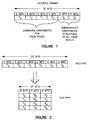
- each 32-bit word of video data consists of four 5-bit components, such as Y 0 through Y 3 , each representing in 5 bits the luminance value of the corresponding pixel of the respective four pixels 0 through 3.
- U 0 and V 0 are each 6-bit components of the 32-bit word and comprise the two chrominance components which will be used for all four pixel luminance values of the 32-bit word.
- luminance values are represented by a 5-bit component and can vary pixel to pixel, whereas the chrominance values are 6-bit components, and are fixed for each group of four pixels.
- the four pixels are four successive pixels in a raster scan image.
- the ability to use the same chrominance information for four successive pixels is due to the fact that the human eye is less sensitive to chrominance information, a fact utilized also in ordinary TV broadcasts, wherein the in-phase and quadrature chrominance signals on the chroma subcarrier have a substantially lower bandwidth than the luminance signal.
- the conversion from Accupac to YUV, and more particularly YUV-444, is very simple, as illustrated in Figure 2.
- the respective two values of chrominance U 0 and V 0 are directly associated, so that now each pixel is represented by a luminance value followed by its two chrominance values, even though the two chrominance values remain constant for four successive pixels.
- the 5 and 6-bit components are expressed in 8-bit byte form by padding the unoccupied bits with zeros.
- circuitry was provided to reformat image data to stretch the image in either direction by a factor of 2, 4 or 8.
- This stretching is on a pixel to pixel basis.
- an image is to be stretched 10% in the horizontal direction.
- This is done in the prior art graphics controller by interpolating between two adjacent pixels in the series of ten pixels, so that pixel data for an 11th pixel is provided. This provides a smoother transition than merely replicating one of the pixels, as replication, particularly as the stretching gets larger, gives the image a grainy appearance.
- the YUV-444 data is merely the YUV data for each successive pixel, as shown.
- an interpolation is made so that data for an additional pixel is determined and effectively interposed between the data for adjacent pixels in the 1-to-1 version of the image data. This is done by taking the average of the luminance values of the two successive pixels (1/2 Y O + 1/2 Y 1 ).
- U 0 and V 0 are already applicable to both Y 0 and Y 1 and, accordingly represent "an average" for these two pixels already.
- U 0 and U 1 could be averaged, as could V 0 and V 1 , though this was not done because of the extra hardware required for minimal gain in visual appearance of the display.
- pixel data for three additional pixels are calculated and effectively interposed between each two pixels in the 1-to-1 image representation.
- These additional three pixels are also interpolations between two adjacent pixels in the 1-to-1 image data, calculated by a 3/4:1/4 weighting, a 1/2:1/2 weighting, and a 1/4:3/4 weighting, respectively in both the luminance and the two chrominance components.
- U 0 and V 0 actually represent that weighting, as U 0 and V 0 are applicable to both pixel 0 and 1 in Figure 3.
- the U and V values associated with one luminance value were used, not an interpolation between the two sets of values, as repacking the Accupac requires the same U and V values for four successive pixels.
- the 8-to-1 stretch is accomplished by merely replicating each pixel obtained from a 4-to-1 stretch.
- circuitry for interpolating two adjacent values of Y, U and V by a 3/4:1/4, 1/2:1/2, and a 1/4:3/4 weighting already exists in the prior art products.
- each successive pixel for display is taken from a different 32-bit image data word, and from its prior Accupac format, has its own unique value of U and V associated with it. Consequently, when converting from YUV-444 back to Accupac, a value for U and V must be selected as representative for four successive pixels, such as Y 3 , Y 7 , Y 11 and Y 15 in the example shown. In the prior art devices, an arbitrary choice was made to always use one of the four sets of values for U and V to avoid the necessity of having to calculate anything different.
- Interpolation or shrinking in the vertical direction does not present the same problems, in that since each four successive (horizontal) pixels have the same values of U and V, interpolation of U and V in the vertical direction or skipping of entire lines will yield the same new values of U and V for each four successive horizontal pixels in the line or lines added by interpolation between two lines of the 1-to-1 image, or used in the shrunken image.
- an Accupac or Accupac-like formatting accommodates different values of U and V between all vertically adjacent pixels, but not horizontally adjacent pixels.
- image size adjustment was done first in the vertical direction, then in the horizontal direction.
- a method and apparatus for determining representative values for the chrominance components to be associated with a plurality of luminance components in a horizontally shrunken image for graphics controllers wherein display image data is stored in a buffer memory in a form associating a single set of U and V chrominance components with a plurality of Y luminance values are disclosed.
- Figure 1 illustrates a specific prior art graphics data format referred to as Accupac, in which pixel data is stored 4 pixels for every 32-bit word.
- Figure 2 illustrates the conversion from Accupac to YUV-444.
- Figure 3 illustrates the manner in which interpolation is carried out in the prior art for image stretching.
- visual characteristics of a shrunken image are enhanced by calculating average or near average values of U and V for each successive group of four pixels in that shrunken image for repacking in Accupac format or an Accupac-like format.
- U and V average or near average values of U and V for each successive group of four pixels in that shrunken image for repacking in Accupac format or an Accupac-like format.
- the general form of YUV-444 data when expanded from Accupac format is shown in Table 2.
- the problem consists of how to reformat the YUV-444 data into an Accupac or Accupac-like format with minimum loss of information in the chrominance values.
- the present invention contemplates the approximation of such averaging through the use of the X interpolator used in the prior art graphics controllers, though with some modification thereto.
- the interpolator includes an A register and a B register, each of which may present the contents thereof less the least significant bit (A1/2, B1/2) and less the two least significant bits (A1/4, B1/4) as their output. Dropping the least significant bit is equivalent to dividing the register contents in half, and dropping the two least significant bits is equivalent to dividing the register contents by four.
- the divided-by-four contents of registers A and B may be passed through multiplexers controlled by control signals XCTL 13 and CTL 13 to X ADDER 0, with the output 1/4 A + 1/4 B providing one input to the X ADDER 1.
- X ADDER 1 The other input to X ADDER 1 is provided by a MUX controlled by X CTL 14, which may pass either 1/2 A or 1/2 B as the second input to X ADDER 1. Accordingly, depending upon the control signal X CTL 14, the output of X ADDER 1 under these conditions is either 3/4 A + 1/4 B or 1/4 A + 3/4 B.
- control signals X CTL 13 and CTL 13 may be used to control the respective MUX's to pass 1/2A as one input to X ADDER 0, and 0 as the other input to the adder X ADDER 0. Consequently, the output of X ADDER 0 in this condition, provided as one input to X ADDER 1, will be 1/2A.
- the other input to X ADDER 1 is controlled by the control signal XCTL 14 to be either 1/2 A or 1/2 B, whereby the output of X ADDER 1 may be selected to be either A or 1/2 A + 1/2 B.
- the interpolator of Figure 1 also includes a multiplexer/holding register identified as MUX/HOLD in the Figure.
- the multiplexer/holding register is controlled by the control signal MIX, and has as one input thereto, feedback from the output of the adder X ADDER 1. Finally, there is a direct path from the B register to the second input of the multiplexer/holding register MUX/Hold.
- the circuit of Figure 3 is used as an X interpolator during the horizontal stretching of an image in a manner well-known in prior art graphics controllers. This current technique won't correctly match up the chrominance when pixels having different U, V values are combined.
- the circuit of Figure 1 is used in a novel manner to calculate approximate average values for U and V to use for multiple pixels when the same multiple pixels have more than one set of U and V values associated therewith.
- the circuit of Figure 1 is used in a novel manner to calculate approximate average values for U and V to use for multiple pixels when the same multiple pixels have more than one set of U and V values associated therewith.
- the circuit of Figure 1 is used in a novel manner to calculate approximate average values for U and V to use for multiple pixels when the same multiple pixels have more than one set of U and V values associated therewith.
- the circuit of Figure 1 is used in a novel manner to calculate approximate average values for U and V to use for multiple pixels when the same multiple pixels have more than one set of U and V values associated therewith.
- the interpolator of Figure 1 is set to calculate 3/4 A + 1/4 B. Initially, the first value of U 0 is provided to the B register, and from there via the multiplexer MUX/Hold to the A register. Then the second value, U 1 , is provided to the B register. Since the circuit is set to provide 3/4 A + 1/4 B as the output of the adder X ADDER 1, the output of X ADDER 1 for the U 0 input to the A register and the U 1 input to the B register will be 3/4 U 0 + 1/4 U 1 . The feedback path couples that output to the A register via the MUX/Hold multiplexer to the input of the A register while U 2 is input to the B register.
- V values may be processed the same as the U values to provide the same form of approximation: V avg ⁇ 27/64 V 0 + 9/64 V 1 + 12/64 V 2 + 16/64 V 3
- Pixel stretching in a horizontal direction has the same properties as when a shrink operation occurs.
- a 2 to 1 stretch operation where combinations of pixels with different chrominance values are recombined.
- the stretch operation in Table 1 when the "2-to-1 stretch" operation is recombined into 32 bit Accupac format, the first 32 bits have matching U and V values for all the Y values.
- the second set of four pixels there is a combination of Y 3 and Y 4 .
- the existing interpolation unit is set to 3/4 first pixel + 1/4 second pixel as is accomplished in a shrink operation. This operation has the effect of blending the color changes more uniformly and is more pleasing to the eye.
- stretch and shrink values can be non-integer quantities (e.g. 3.06) for this invention.
- the interpolator processed the values in a fixed 3/4 A + 1/4 B format. If desired, the weighting of the chrominance components and the feedback of the sum could be altered to perhaps provide an even superior approximation.
- the prior art interpolator does not include the capability of altering the weighting during the processing, and the approximation attained without adding such additional control is adequate for the purposes intended without complicating the control circuitry for this purpose.
Landscapes
- Engineering & Computer Science (AREA)
- Physics & Mathematics (AREA)
- General Physics & Mathematics (AREA)
- Theoretical Computer Science (AREA)
- Computer Hardware Design (AREA)
- Multimedia (AREA)
- Signal Processing (AREA)
- Image Processing (AREA)
- Processing Of Color Television Signals (AREA)
- Controls And Circuits For Display Device (AREA)
- Editing Of Facsimile Originals (AREA)
Applications Claiming Priority (2)
| Application Number | Priority Date | Filing Date | Title |
|---|---|---|---|
| US55079495A | 1995-10-31 | 1995-10-31 | |
| US550794 | 1995-10-31 |
Publications (2)
| Publication Number | Publication Date |
|---|---|
| EP0772179A2 true EP0772179A2 (de) | 1997-05-07 |
| EP0772179A3 EP0772179A3 (de) | 1998-10-21 |
Family
ID=24198595
Family Applications (1)
| Application Number | Title | Priority Date | Filing Date |
|---|---|---|---|
| EP96307847A Withdrawn EP0772179A3 (de) | 1995-10-31 | 1996-10-30 | Verfahren und Vorrichtung zur Bestimmung von Chrominanzkomponenten |
Country Status (4)
| Country | Link |
|---|---|
| US (1) | US5929837A (de) |
| EP (1) | EP0772179A3 (de) |
| JP (1) | JPH09204171A (de) |
| TW (1) | TW320807B (de) |
Cited By (2)
| Publication number | Priority date | Publication date | Assignee | Title |
|---|---|---|---|---|
| US6529244B1 (en) | 1999-12-22 | 2003-03-04 | International Business Machines Corporation | Digital video decode system with OSD processor for converting graphics data in 4:4:4 format to 4:2:2 format by mathematically combining chrominance values |
| WO2002048960A3 (en) * | 2000-12-12 | 2003-07-24 | Sharp Kk | Methods and systems for improving display resolution in images using sub-pixel sampling and visual error filtering |
Families Citing this family (2)
| Publication number | Priority date | Publication date | Assignee | Title |
|---|---|---|---|---|
| JP4794911B2 (ja) | 2005-05-31 | 2011-10-19 | キヤノン株式会社 | 画像処理装置 |
| US8031973B2 (en) * | 2006-03-07 | 2011-10-04 | Brother Kogyo Kabushiki Kaisha | Data processing device capable of executing retinex processing at high speed |
Family Cites Families (14)
| Publication number | Priority date | Publication date | Assignee | Title |
|---|---|---|---|---|
| US4315278A (en) * | 1980-05-23 | 1982-02-09 | Ampex Corporation | Apparatus for providing error compensation in a digital video recording and reproducing system |
| DE3121847C2 (de) * | 1981-06-02 | 1987-04-16 | Robert Bosch Gmbh, 7000 Stuttgart | Verfahren zur Übertragung und/oder Speicherung digital codierter Farbfernsehsignale |
| NL8500735A (nl) * | 1985-03-14 | 1986-10-01 | Philips Nv | Systeem voor het regelsgewijs in een compressie-inrichting comprimeren van binaire data van een beeldveld, decompressie-inrichting voor gebruik in zo een systeem en afbeeldinrichting voorzien van zo een decompressie-inrichting. |
| US4752983A (en) * | 1987-07-09 | 1988-06-28 | Grieshaber Herman R | Surgical instrument cleaning device |
| GB2207029A (en) * | 1987-07-14 | 1989-01-18 | Silicongraphics Inc | Computer system for converting a higher resolution image to a lower resolution image |
| US5003299A (en) * | 1988-05-17 | 1991-03-26 | Apple Computer, Inc. | Method for building a color look-up table |
| US5202756A (en) * | 1988-11-09 | 1993-04-13 | Canon Kabushiki Kaisha | Color signal processing apparatus using plural luminance signals |
| US5081450A (en) * | 1990-03-09 | 1992-01-14 | International Business Machines Corporation | Apparatus and method for compressing and expanding multibit digital pixel data |
| US5170152A (en) * | 1990-12-14 | 1992-12-08 | Hewlett-Packard Company | Luminance balanced encoder |
| US5402513A (en) * | 1991-10-15 | 1995-03-28 | Pixel Semiconductor, Inc. | Video window generator with scalable video |
| US5469190A (en) * | 1991-12-23 | 1995-11-21 | Apple Computer, Inc. | Apparatus for converting twenty-four bit color to fifteen bit color in a computer output display system |
| DE69329983T2 (de) * | 1992-08-21 | 2001-08-02 | Canon K.K., Tokio/Tokyo | Bildverarbeitungsverfahren und -vorrichtung |
| DE4309471A1 (de) * | 1993-03-24 | 1994-09-29 | Miro Computer Prod Ag | Verfahren zur Wiedergabe von Videobildern |
| US5577203A (en) * | 1993-07-29 | 1996-11-19 | Cirrus Logic, Inc. | Video processing methods |
-
1996
- 1996-10-30 TW TW085113272A patent/TW320807B/zh not_active IP Right Cessation
- 1996-10-30 EP EP96307847A patent/EP0772179A3/de not_active Withdrawn
- 1996-10-31 JP JP8290657A patent/JPH09204171A/ja active Pending
-
1998
- 1998-03-02 US US09/107,579 patent/US5929837A/en not_active Expired - Lifetime
Non-Patent Citations (1)
| Title |
|---|
| None |
Cited By (2)
| Publication number | Priority date | Publication date | Assignee | Title |
|---|---|---|---|---|
| US6529244B1 (en) | 1999-12-22 | 2003-03-04 | International Business Machines Corporation | Digital video decode system with OSD processor for converting graphics data in 4:4:4 format to 4:2:2 format by mathematically combining chrominance values |
| WO2002048960A3 (en) * | 2000-12-12 | 2003-07-24 | Sharp Kk | Methods and systems for improving display resolution in images using sub-pixel sampling and visual error filtering |
Also Published As
| Publication number | Publication date |
|---|---|
| JPH09204171A (ja) | 1997-08-05 |
| EP0772179A3 (de) | 1998-10-21 |
| US5929837A (en) | 1999-07-27 |
| TW320807B (de) | 1997-11-21 |
Similar Documents
| Publication | Publication Date | Title |
|---|---|---|
| US5517612A (en) | Device for scaling real-time image frames in multi-media workstations | |
| US5587928A (en) | Computer teleconferencing method and apparatus | |
| EP0391094B1 (de) | Fernseh-Abtastzeilenverdoppler mit einem zeitlichen Mittelwertfilter | |
| EP0806110B1 (de) | Flimmerreduzierungund bildgrösseneinstellung für einen videokontroller mit zeilensprungvideoausgang | |
| KR100195590B1 (ko) | 2단 보간 시스템 | |
| US5097257A (en) | Apparatus for providing output filtering from a frame buffer storing both video and graphics signals | |
| US5119082A (en) | Color television window expansion and overscan correction for high-resolution raster graphics displays | |
| US5185666A (en) | Digitized film image processing system with bordered split screen display | |
| US5260695A (en) | Color map image fader for graphics window subsystem | |
| US6005638A (en) | Frame averaging for use in processing video data | |
| US5321500A (en) | Non-real-time film scanning system | |
| EP0762325A2 (de) | Videovergrösserungsgerät | |
| US5327242A (en) | Video noise reduction apparatus and method using three dimensional discrete cosine transforms and noise measurement | |
| JPH0326600B2 (de) | ||
| JPH01204589A (ja) | 色補正方法 | |
| US6778187B1 (en) | Methods and devices to process graphics and/or video data | |
| CA1233554A (en) | Interlace to non-interlace scan converter for rgb format video input signals | |
| US6151135A (en) | Method and apparatus for color reproduction | |
| US6154195A (en) | System and method for performing dithering with a graphics unit having an oversampling buffer | |
| US5943097A (en) | Image processing means for processing image signals of different signal formats | |
| US5181100A (en) | Digital video processing system with mixing prefilter | |
| JPH05284388A (ja) | ビデオ信号の高周波数応答特性を変更するための装置 | |
| US6259439B1 (en) | Color lookup table blending | |
| US5231385A (en) | Blending/comparing digital images from different display window on a per-pixel basis | |
| US5929837A (en) | Method and apparatus for determining representative chrominance components |
Legal Events
| Date | Code | Title | Description |
|---|---|---|---|
| PUAI | Public reference made under article 153(3) epc to a published international application that has entered the european phase |
Free format text: ORIGINAL CODE: 0009012 |
|
| AK | Designated contracting states |
Kind code of ref document: A2 Designated state(s): BE DE ES FR GB IE IT NL PT |
|
| PUAL | Search report despatched |
Free format text: ORIGINAL CODE: 0009013 |
|
| AK | Designated contracting states |
Kind code of ref document: A3 Designated state(s): BE DE ES FR GB IE IT NL PT |
|
| 17P | Request for examination filed |
Effective date: 19981126 |
|
| STAA | Information on the status of an ep patent application or granted ep patent |
Free format text: STATUS: THE APPLICATION IS DEEMED TO BE WITHDRAWN |
|
| 18D | Application deemed to be withdrawn |
Effective date: 20010502 |
|
| REG | Reference to a national code |
Ref country code: HK Ref legal event code: WD Ref document number: 1010005 Country of ref document: HK |