EP0772325A2 - Système de commutation ATM et méthode de contrÔle de priorité - Google Patents
Système de commutation ATM et méthode de contrÔle de priorité Download PDFInfo
- Publication number
- EP0772325A2 EP0772325A2 EP19960117447 EP96117447A EP0772325A2 EP 0772325 A2 EP0772325 A2 EP 0772325A2 EP 19960117447 EP19960117447 EP 19960117447 EP 96117447 A EP96117447 A EP 96117447A EP 0772325 A2 EP0772325 A2 EP 0772325A2
- Authority
- EP
- European Patent Office
- Prior art keywords
- band width
- counter
- class
- value
- cells
- Prior art date
- Legal status (The legal status is an assumption and is not a legal conclusion. Google has not performed a legal analysis and makes no representation as to the accuracy of the status listed.)
- Granted
Links
- 238000000034 method Methods 0.000 title claims abstract description 59
- 238000004891 communication Methods 0.000 claims abstract description 97
- 239000000872 buffer Substances 0.000 claims description 136
- 230000002411 adverse Effects 0.000 description 10
- 238000010586 diagram Methods 0.000 description 8
- 230000002159 abnormal effect Effects 0.000 description 7
- 239000010750 BS 2869 Class C2 Substances 0.000 description 6
- 230000000694 effects Effects 0.000 description 6
- 230000006870 function Effects 0.000 description 6
- 239000010749 BS 2869 Class C1 Substances 0.000 description 5
- 230000005540 biological transmission Effects 0.000 description 4
- 230000005856 abnormality Effects 0.000 description 3
- 230000003247 decreasing effect Effects 0.000 description 3
- 230000006727 cell loss Effects 0.000 description 2
- 238000010276 construction Methods 0.000 description 2
- 230000006378 damage Effects 0.000 description 2
- 230000000593 degrading effect Effects 0.000 description 2
- 230000007423 decrease Effects 0.000 description 1
- 230000000007 visual effect Effects 0.000 description 1
Images




Classifications
-
- H—ELECTRICITY
- H04—ELECTRIC COMMUNICATION TECHNIQUE
- H04L—TRANSMISSION OF DIGITAL INFORMATION, e.g. TELEGRAPHIC COMMUNICATION
- H04L49/00—Packet switching elements
- H04L49/30—Peripheral units, e.g. input or output ports
- H04L49/3081—ATM peripheral units, e.g. policing, insertion or extraction
-
- H—ELECTRICITY
- H04—ELECTRIC COMMUNICATION TECHNIQUE
- H04L—TRANSMISSION OF DIGITAL INFORMATION, e.g. TELEGRAPHIC COMMUNICATION
- H04L49/00—Packet switching elements
- H04L49/20—Support for services
- H04L49/205—Quality of Service based
-
- H—ELECTRICITY
- H04—ELECTRIC COMMUNICATION TECHNIQUE
- H04L—TRANSMISSION OF DIGITAL INFORMATION, e.g. TELEGRAPHIC COMMUNICATION
- H04L12/00—Data switching networks
- H04L12/54—Store-and-forward switching systems
- H04L12/56—Packet switching systems
- H04L12/5601—Transfer mode dependent, e.g. ATM
- H04L2012/5629—Admission control
- H04L2012/5631—Resource management and allocation
- H04L2012/5632—Bandwidth allocation
-
- H—ELECTRICITY
- H04—ELECTRIC COMMUNICATION TECHNIQUE
- H04L—TRANSMISSION OF DIGITAL INFORMATION, e.g. TELEGRAPHIC COMMUNICATION
- H04L12/00—Data switching networks
- H04L12/54—Store-and-forward switching systems
- H04L12/56—Packet switching systems
- H04L12/5601—Transfer mode dependent, e.g. ATM
- H04L2012/5638—Services, e.g. multimedia, GOS, QOS
- H04L2012/5646—Cell characteristics, e.g. loss, delay, jitter, sequence integrity
- H04L2012/5651—Priority, marking, classes
-
- H—ELECTRICITY
- H04—ELECTRIC COMMUNICATION TECHNIQUE
- H04L—TRANSMISSION OF DIGITAL INFORMATION, e.g. TELEGRAPHIC COMMUNICATION
- H04L12/00—Data switching networks
- H04L12/54—Store-and-forward switching systems
- H04L12/56—Packet switching systems
- H04L12/5601—Transfer mode dependent, e.g. ATM
- H04L2012/5672—Multiplexing, e.g. coding, scrambling
-
- H—ELECTRICITY
- H04—ELECTRIC COMMUNICATION TECHNIQUE
- H04L—TRANSMISSION OF DIGITAL INFORMATION, e.g. TELEGRAPHIC COMMUNICATION
- H04L49/00—Packet switching elements
- H04L49/30—Peripheral units, e.g. input or output ports
Definitions
- This invention relates to an Asynchronous Transfer Mode (referred to as ATM, hereinafter) exchange system used in a multimedia communication system basically through a buffer memory. More specifically this invention relates to a priority control method preventing an adverse influence caused by an abnormal traffic generated in a certain communication quality class among those defined by the required communication quality from being exerted to the rest of the classes.
- ATM Asynchronous Transfer Mode
- the multimedia communication system basically through the buffer memory provides services requiring communication quality from various aspects such as real time processability, low destruction rate, "Best effort” transfer and the like.
- the following services have been provided such as Circuit Emulation, Constant Bit Rate Video service (referred to as CBR class, hereinafter) at a constant transmission bit rate requiring strict standard on delay or cell loss; Audio and visual service at a variable bit rate requiring real time processability (referred to as rt-VBR class, hereinafter); Data service at a variable bit rate requiring no real time processability (referred to as nrt-VBR class, hereinafter); the service at a variable bit rate requiring the best effort transfer and strict standard on cell loss (referred to as ABR class, hereinafter); the service requiring destruction and fairness at every cell (referred to as UBR class, hereinafter) and the like.
- the priority control method in the ATM exchange system is effective for meeting the above-described different types of required communication quality simultaneously.
- an initial priority level is set to each communication quality class defined by the required communication quality. If a waiting queue length of each communication quality class is smaller than a threshold value specified with respect to the respective communication quality classes, priority control is executed according to the initial priority level set to the respective communication quality classes. If a certain communication quality class has a waiting queue length equal to or larger than a threshold value, the priority level of the class is raised 1 level higher and the priority control will be executed according to the changed priority level. In case of those communication quality classes provided with the same priority, a rotational priority control is executed. The rotational priority control is done by outputting the cell from buffers of those classes one by one alternately.
- Fig. 16 shows a more detailed explanation of the above-described prior art. In Fig. 16, it is assumed that 3 classes are priority controlled.
- the initial priority level is set to communication quality classes C1, C2 and C3, respectively according to the communication quality required by those communication quality classes C1, C2 and C3.
- each priority 2, 3 and 4 is given to the communication quality classes C1, C2 and C3, respectively.
- Threshold values Th1, Th2 and Th3 are also set to the communication quality classes C1, C2 and C3 according to the communication quality required by the C1, C2 and C3.
- the cell stored in a buffer B1 of the communication quality class C1 is output with the highest priority according to the initial priority level.
- a cell stored in a buffer B2 of the communication quality class C2 is output only when the buffer B1 stores no cells.
- a cell stored in a buffer B3 of the communication quality class C3 is output only when both buffers B1 and B2 store no cells.
- the priority level of the communication quality class is changed from 3 to 2, thus changing the priority level of the C1, C2 and C3 to 2, 2 and 4, respectively.
- the rotational priority control is executed between the classes C1 and C2 at the same priority level.
- the priority level of the communication quality class C2 is restored to 3 as the original priority level.
- the priority level of the communication quality class is raised to one level up.
- communication quality of the other classes may be adversely influenced.
- the waiting queue length Q2 exceeds the threshold value Th2 due to the increased traffic amount in the communication quality class C2
- the number of cells in the communication quality class C1 output in a unit of time is decreased, resulting in degraded communication quality.
- the waiting queue length Q3 of the communication quality class C3 further exceeds the threshold value Th3. Even though the priority level of the C3 is raised from 4 to 3, the priority of the class C2 has been set to 2 and cells are never output from the communication quality class C3 even if the buffer for the communication quality class C1 stores no cells.
- the priority level of the communication quality class is raised to one level up. If the traffic amount is increased for some reason to have the waiting queue length exceed the threshold value in a certain communication quality class, communication quality of the other classes may be adversely influenced. For example, when the waiting queue length Q2 exceeds the threshold value Th2 due to the increased traffic amount in the communication quality class C2, the number of cells in the communication quality class C1 output in a unit of time is decreased, resulting in degraded communication quality. The waiting queue length Q3 of the communication quality class C3 further exceeds the threshold value Th3. Even though the priority level of the C3 is raised from 4 to 3, the priority of the class C2 has been set to 2 and cells are never output from the communication quality class C3 even if the buffer for the communication quality class C1 stores no cells.
- an ATM exchange system for receiving a plurality of calls each having different required communication quality comprising: a buffer for providing each of a plurality of band width demand classes that have been defined according to required communication quality for storing call cells belonging to the respective band width demand classes; a counter for providing each of said respective band width demand classes; call reception control means for setting a guaranteed band width represented by the number of cells per certain time required to be output to an output channel for assuring each communication quality of said respective band width demand classes at said certain time interval; and priority control means for outputting cells stored in a buffer for a band width demand class having a counter value not set to 0 to said output channel, subtracting 1 from a value set in a counter of a band width demand class that has output cells at every output of cells to said output channel and outputting cells stored in a buffer for a band width demand class having a counter value 0.
- a call reception control means sets a guaranteed band width represented by the number of cells per a certain time required to be output for assuring communication quality of the respective band width demand classes at a certain time interval.
- a value of the counter of each band width demand class is subjected to subtraction through a priority control process means at every output of the cell from the corresponding band width demand class buffer.
- the priority control process means outputs the cell from the buffer for the band width demand class in which the N counter value has not reached 0 and outputs the cell stored in the band width demand class outputting the cell with the highest priority. That is the number of cells required to assure the communication quality of each band width demand classes is output.
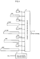
- Fig. 1 is a block diagram of an embodiment of the present invention comprising a call reception control circuit 1, a priority control process circuit 2, an output channel 3, a band width demand class buffer CBR, rt-VBR, nrt-VBR, a best effort transfer demand class buffers ABR and UBR, N counters (Nc, Ntv and Nv) and W counters (Wabr and Wubr).
- the band width demand class buffers CBR, rt-VBR and nrt-VBR store the cell related to the call belonging to the corresponding CBR class, rt-VBR class and nrt-VBR class resulted from classifying the call for band width demand according to the required communication quality.
- the best effort transfer demand class buffers ABR and UBR store the cell related to the call belonging to the corresponding best effort class ABR class and UBR class resulted from classifying the call for the best effort transfer demand to use the remained band width according to the required communication quality.
- the N counters Nc, Ntv and Nv are provided for the CBR class, rt-VBR class and nrt-VBR class, respectively.
- the W counters Wabr and Wubr are provided for the ABR class and the UBR class, respectively.
- the call reception control circuit 1 has various functions for setting a guaranteed band width represented by the number of cells per certain time Ts which is required to be output to the output channel 3 for assuring each communication quality of the CBR class, rt-NBR class and nrt-VBR class in the N counter Nc, Ntv and Nv of the CBR class, rt-VBR class and nrt-VBR class, respectively and for setting values defined by a ratio of the ABR class and UBR class to use the remained band width represented by the number of cells output to the output channel 3 per certain time Ts resulted from taking the guaranteed band widths for the CBR class, rt-VBR class and nrt-VBR class from the whole band width in the W counter Wabr and Wubr when at least one of the Wabr or Wubr has a value set to 0 and both the ABR class and the UBR class are suspended (The value of the W counter either Wabr or Wubr is 0 or the best effort transfer demand class buffer
- the priority control process circuit 2 has functions for outputting cells stored in buffers CBR, rt-VBR, nrt-VBR, ABR and UBR to the output channel 3 according to the priority level defined by each value of N counter Nc, Ntv, Nv and the W counter Wabr, Wubr and the respective class for subtracting 1 from the value of the N counter Nc, Ntv and Nv or the W counters Wabr and Wubr not set to 0 in the class outputting the cell.
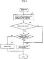
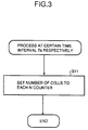
- Figs. 2 and 3 are flowcharts representing an example of processing in the call reception control circuit 1.
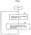
- Fig. 4 is a flowchart representing an example of processing in the priority control process circuit 2. The operation of the embodiment is hereinafter described referring to the drawings.
- the call reception control circuit 1 determines the class to which the generated call belongs (S1). When the call is determined to belong to any of the CBR class, rt-VBR class or nrt-VBR class for band width demand, it is further determined whether or not the call reception results in consuming the remained band width (S2 and S3).
- the call reception control circuit 1 increases the guaranteed band width for the class to which the received call belongs among guaranteed band width for the respective band width demand classes (CBR class, rt-VBR class and nrt-VBR class) by the value corresponding to the communication quality required by the received call as well as decreasing the value equal to the increment from the remained band width under control.
- CBR class, rt-VBR class and nrt-VBR class the respective band width demand classes
- the call reception control circuit 1 decreases the guaranteed band width for the terminated call by a value corresponding to the communication demand quality of the call as well as increasing the remained band width by the value equal to the above-described decrement.
- the call reception control circuit 1 executes the process at S4.
- the call reception control circuit 1 sets each guaranteed band width of the CBR class, rt-VBR class and nrt-VBR class under control to the corresponding N counters Nc, Ntv and Nv, respectively at a certain time interval Ts as shown in a flow chart of Fig. 3 (S11),
- the call reception control circuit 1 sets values defined by a ratio of the W counter Wabr and Wubr to use the remained band width in case at least one of either Wabr or Wubr has a count value 0 and both ABR class and UBR class are suspended.
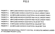
- the priority control process circuit 2 outputs 1 cell according to the priority level shown in Fig. 5.
- the processing for subtracting 1 from the counter value is executed repeatedly (S21 and S22).
- the following process is executed at a certain time interval Ts by outputting the cell according to the priority level shown in Fig. 5. That is, the cell is output from the band width demand class buffer CBR until the value of the N counter Nc of the CBR class becomes 0 or the band width demand class buffer CBR becomes empty (in case of number of cells stored in the buffer CBR less than the N counter Nc value) (priority 1). Then the cell is output from the band width demand class buffer rt-VBR until the value of the N counter Ntv of the rt-VBR class becomes 0 or the band width demand class buffer rt-VBR becomes empty (in case of number of cells stored in the buffer rt-VBR less than the N counter Ntv value) (priority 2).
- the cell is output from the band width demand class buffer nrt-VBR until the value of the N counter Nv of the nrt-VBR class becomes 0 or the band width demand class buffer nrt-VBR becomes empty (in case of number of cells stored in the buffer nrt-VBR less than the N counter Nv value) (priority 3).
- the number of cells required for assuring each communication quality of the CBR class, rt-VBR class and nrt-VBR class are preferentially output from the band width demand class buffers CBR, rt-VBR and nrt-VBR, respectively.
- the cells stored in the best effort transfer demand class buffers ABR and UBR for the ABR class and UBR class are output to the output channel 3 through weighted rotational priority control (Priority 4).
- the weighted rotational priority stands for outputting cells from the respective buffers according to a predetermined ratio. For example, supposing that the weighted rotational priority control is executed between the ABR class and UBR class in the ratio of 2:1, 2 cells are output from the best effort transfer demand class buffer ABR for the ABR class. While 1 cell is output from the best effort transfer demand class buffer UBR for the UBR class. In the above case, the ABR class has better delay characteristics than those of the UBR class.
- cells stored in the band width demand class buffers CBR, rt-VBR and nrt-VBR for the CBR class, rt-VBR class and nrt-VBR class, having the value of the N counter Nc, Nt and Nv set to 0 are output to the output channel 3 (Priority level 5 to 7).
- the higher priority class buffer preferentially outputs the cell.
- the number of cells required for assuring each communication quality of the CBR class, rt-VBR class and nrt-VBR class is output from the band width demand class buffers CBR, rt-VBR and nrt-VBR, respectively at a certain time interval Ts. Therefore even if the abnormal traffic is generated in a certain band width demand class among those CBR class, rt-VBR class and nrt-VBR class, communication quality of the rest of the band width demand classes are guaranteed.
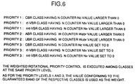
- Priority levels shown in Fig. 6 can be used for reducing the aforementioned adverse influence.
- Fig. 7 is a block diagram of other embodiment of the present invention.
- This embodiment is constructed by adding addition means 4, S counters Sc, Stv, Sv, Sabr and Subr for the CBR class, rt-VBR class, nrt-VBR class, ABR class and UBR class, respectively to the construction of the embodiment shown in Fig. 1.
- a call reception control circuit 11 and a priority control process circuit 12 are provided in place of the call reception control circuit 1 and the priority control process circuit 2 in the embodiment shown in Fig. 1.
- the call reception control circuit 11 has a similar construction to that of the call reception control circuit 1 of Fig. 1.
- the call reception control circuit 1 of Fig. 1 sets a value larger than the logically obtained guaranteed band width in the N counter Nc, Ntv and Nv. On the contrary, the call reception control circuit 11 sets the logically obtained guaranteed band width in each of the N counter Nc, Ntv and Nv.
- the priority control process circuit 12 has the following functions; for outputting cells to the output channel 3 according to the priority level defined by each value of N counter Nc, Ntv, Nv, W counter of Wabr, Wubr, S counter Sc, Stv, Sv, Sabr, Subr and the CBR class, rt-VBR class, nrt-VBR class, ABR class and UBR class; for subtracting the value 1 from the value of the N counter Nc, Ntv and Nv not set to 0 in the class outputting the cell when the cell is output from the CBR class, rt-VBR class and nrt-VBR class having the N counter value Nc, Ntv and Nv larger than 0,; for subtracting the value 1 from the value of the W counter Wabr and Wubr not set to 0 in the class outputting the cell when the cell is output from the ABR class and UBR class having the W counter value Wabr and Wubr larger than 0; for subtracting the value 1 from the value of the S counter
- the addition means 4 has the following functions for: setting values (Sc+Nc), (Stv+Ntv) and (Sv+Nv) obtained by adding each value set in the S counter Sc, Stv and Sv to each value set in the N counter Nc, Ntv and Nv, respectively before setting the guaranteed band width in the N counter Nc, Ntv and Nv through the call reception control circuit 11; and setting values (Sabr+Wabr) and (Subr+Wubr) obtained by adding each value set in the S counter Sabr and Subr to the value set in the W counter Wabr and Wubr in the S counter Sabr and Subr, respectively just before setting the value in the W counter Wabr and Wubr through the call reception control circuit 11.
- the call reception control circuit 11 executes the same processes shown in the flowchart of Fig. 2.
- the call reception control circuit 11 sets the guaranteed band width in each of the N counter Nc, Ntv and Nv and in the W counter Wabr and Wubr, respectively in a similar way.
- the addition means 4 sets values (Sc+Nc), (Stv+Ntv) and (Sv+Nv) obtained by adding each value set in the S counter Sc, Stv and Sv to the value set in the N counter Nc, Ntv and Nv in the S counter Sc, Stv and Sv, respectively just before setting the guaranteed band width in the N counter Nc, Ntv and Nv through the call reception control circuit 11 and sets values (Sabr+Wabr) and (Subr+Wubr) obtained by adding each value set in the S counter Sabr and Subr to the value set in the W counter Wabr and Wubr, respectively just before setting the value in the W counter Wabr and Wubr through the call reception control circuit 11.
- the priority control process circuit 12 outputs 1 cell according to the priority level shown in Fig. 8.
- the CBR class, rt-VBR class and nrt-VBR class having a value of the N counter Nc, Ntv and Nv larger than 0 outputs the cell
- the value 1 is subtracted from the value of the N counter Nc, Ntv and Nv in the class outputting the cell.
- the ABR class and UBR class having the value of the W counter Wabr and Wubr larger than 0 outputs the cell
- the value 1 is subtracted from the value of the W counter Wabr and Wubr in the class outputting the cell.
- the following process is executed at a certain time interval Ts.
- the band width demand class buffer rt-VBR outputs cells until the value of the N counter Ntv of the rt-VBR class is set to 0 or the band width demand class buffer rt-VBR becomes empty (in case of number of cells stored in the buffer rt-VBR less than the N counter Ntv value) (Priority 2).
- the band width demand class buffer nrt-VBR outputs cells until the value of the N counter Nv of the nrt-VBR class is set to 0 or the band width demand class buffer nrt-VBR becomes empty (in case of number of cells stored in the buffer nrt-VBR less than the N counter Nv value) (Priority 3).
- the band width demand class buffer CBR outputs cells until the value of the S counter Sc is set to 0 or the band width demand class buffer CBR becomes empty (in case of number of cells stored in the buffer CBR less than the S counter Sc value) (Priority 4).
- the band width demand class buffer rt-VBR outputs cells until the value of the S counter Stv is set to 0 or the band width demand class buffer rt-VBR becomes empty (in case of number of cells stored in the buffer rt-VBR less than the S counter Stv value) (Priority 5).
- the band width demand class buffer nrt-VBR outputs cells until the value of the S counter Sv is set to 0 or the band width demand class buffer nrt-VBR becomes empty (in case of number of cells stored in buffer nrt-VBR less than the S counter Sv value) (Priority 6).
- the cells stored in the best effort transfer demand class buffers ABR and UBR for the ABR class and the UBR class are output to the output channel 3 through the weighted rotational priority control (Priority 7).
- the cells stored in the band width demand class buffers CBR, rt-VBR and nrt-VBR for the CBR class, rt-VBR class and nrt-VBR class having both values of the N counter Nc, Ntv and Nv and the S counter Sc, Stv and Sv set to 0 are output to the output channel 3 (Priority 8 to 10).
- the higher priority class buffer preferentially outputs the cell.
- the present invention sets a higher priority to the CBR class, rt-VBR class and nrt-VBR class having the value of the N counter Nc, Ntv and Nv larger than 0 over the CBR class, rt-VBR class and nrt-VBR class having the value of the S counter Sc, Stv and Sv larger than 0.
- the following is the reason why the above-described priority setting has been defined.
- the cells do not always reach the exchange office at the above-specified bit rate. For example, supposing that the cell transmission source outputs 1000 cells per certain time Ts, it is often the case that only 900 cells reach within the certain time Ts and then in the next time Ts, 1100 cells reach.
- a logically guaranteed band width for assuring the communication quality is set to 1000 cell/Ts and only 900 cells are output in the first certain time interval Ts, then 1100 cells are output in the next certain time Ts to the band width demand class buffer CBR for the CBR class.
- the N counter Nc has the guaranteed band width set to 1000 cells at a certain time interval Ts.
- the N counter Nc is not set to 0 but to 100 even though all the cells stored in the band width demand class buffer CBR are output.
- the Nc value 100 is added to the value currently set in the S counter Sc. For example, the Sc value is changed from 0 to 100.
- the guaranteed band width value has to be larger than 1000 cells/Ts (for example, 1100 cells/Ts).
- the guaranteed band width for assuring the same communication quality can be reduced compared with the embodiment of Fig. 1.
- the number of received calls can be increased compared with the embodiment of Fig. 1. That is in case a total of each guaranteed band width of the CBR class, rt-VBR class and nrt-VBR class becomes larger than the whole band width of the output channel 3, the call has to be rejected.
- the guaranteed band width is reduced, the number of calls for reception can be increased.
- the priority level shown in Fig. 9 can be used in place of the priority level shown in Fig. 8 for preventing the higher priority class from giving an adverse effect on the lower priority class.
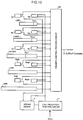
- Fig. 10 is a block diagram of other embodiment of the present invention.
- a priority control process circuit 22 is used in place of the priority control process circuit 12 shown in Fig. 7.
- the priority control process circuit 22 outputs cells to the output channel 3 according to the priority defined by each value of the N counter Nc, Ntv and Nv, the W counter Wabr and Wubr, the S counter Sc, Stv, Sv, Sabr and Subr, the CBR class, rt-VBR class, nrt-VBR class, ABR class and UBR class and each of the first threshold value of Thc1, Thtv1 and Thv1 for the respective CBR class, rt-VBR class and nrt-VBR class.
- Other functions of the priority control process circuit 22 are the same as those of the priority control process circuit 12 shown in Fig. 7.
- the threshold values Thc1, Thtv1 and Thv1 correspond to the number of cells (waiting queue length Qc, Qtv and Qv) stored in the respective band width demand class buffers CBR, rt-VBR and nrt-VBR. Those threshold values are set conforming to the communication quality required by each of the CBR class, rt-VBR class and nrt-VBR class.
- the call reception control circuit 11 and addition means 4 execute the same processing as aforementioned.
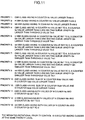
- the priority control process circuit 22 outputs 1 cell according to the priority level shown in Fig. 11.
- the CBR class, rt-VBR class and nrt-VBR class having the value of the N counter Nc, Ntv and Nv larger than 0 outputs the cell
- the value 1 is subtracted from the value of the N counter Nc, Ntv and Nv not set to 0 in the class outputting the cell.
- the ABR class and UBR class having the value of the W counter Wabr and Wubr larger than 0 outputs the cell
- the value 1 is subtracted from the value of the W counter Wabr and Wubr not set to 0 in the class outputting the cell.
- First cells are output from the band width demand class buffers CBR, rt-VBR and nrt-VBR for the CBR class, rt-VBR class and nrt-VBR class having the value of the N counter Nc, Ntv and Nv larger than 0 (Priority levels 1 to 3).
- Cells are output from the band width demand class buffers CBR, rt-VBR and nrt-VBR for the CBR class, rt-VBR class and nrt-VBR class having the value of the S counter Sc, Stv and Sv larger than 0 and the waiting queue length Qc, Qtv and Qv larger than the threshold value Thc1, Thtv1 and Thv1, respectively (Priority levels 4 to 6).
- Cells are output from the band width demand class buffers CBR, rt-VBR, nrt-VBR for the CBR class, rt-VBR class and nrt-VBR class having the value of the S counter Sc, Stv and Sv larger than 0 and the waiting queue length Qc, Qtv and Qv smaller than the threshold value Thc1, Thtv1 and Thv1, respectively (Priority level 7 to 9).
- the cells stored in the best effort transfer demand class buffers ABR and UBR for the ABR class and UBR class are output to the output channel 3 through the weighted rotational priority control (Priority level 10).
- the cells stored in the band width demand class buffers CBR, rt-VBR and nrt-VBR for the CBR class, rt-VBR class and nrt-VBR class having both values of the N counter Nc, Ntv and Nv and the S counter Sc, Stv and Sv set to 0 are output to the output channel 3 (Priority levels 11 to 13).
- the higher priority class buffer preferentially outputs the cell.
- the highest priority is given to the CBR class, rt-VBR class and nrt-VBR class having the value of the N counter Nc, Ntv and Nv larger than 0.
- the second highest priority is given to the CBR class, rt-VBR class and nrt-VBR class having the value of the S counter Sc, Stv and Sv larger than 0 and each having the waiting queue length Qc, Qtv and Qv larger than the first threshold value Thc1, Thtv1 and Thv1, respectively.
- the third priority is given to the CBR class, rt-VBR class and nrt-VBR class having the value of the S counter Sc, Stv and Sv larger than 0 and the waiting queue length Qc, Qtv and Qv smaller than the first threshold value Thc1, Thtv1 and Thv1, respectively. Therefore the communication quality of the CBR class, rt-VBR class and nrt-VBR class having the waiting queue length elongated owing to abnormality generated in the traffic can be guaranteed to some extent without degrading the communication quality of other band width demand classes.
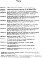
- the priority level shown in Fig. 12 can be used in place of those shown in Fig. 11 for preventing the higher priority class from giving an adverse effect on the lower priority class.
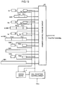
- Fig. 13 is a block diagram of a still further embodiment of the present invention. This embodiment uses a priority control process circuit 32 in place of the priority control process circuit 22 shown in Fig. 10.
- the priority control process circuit 32 outputs cells to the output channel 3 according to the priority level defined by each value of the N counter Nc, Ntv and Nv; W counter Wabr and Wubr; S counter Sc, Stv, Sv, Sabr and Subr; the CBR class, rt-VBR class, ABR class, UBR class; the first threshold value Thc1, Thtv1 and Thv1 for the CBR class, rt-VBR class and nrt-VBR class; and the second threshold value Thc2, Thtv2 and Thv2 for the CBR class, rt-VBR class and nrt-VBR class, respectively.
- Other functions are the same as those of the priority control process circuit 22 shown in Fig. 10.
- the threshold values Thc2, Thtv2 and Thv2 correspond to the waiting queue length Qc, Qtv and Qv for the CBR class, rt-VBR class and nrt-VBR class,respectively which are set in consideration of the traffic generated unexpectedly.
- the call reception control circuit 11 and the addition means 4 execute the same processing as aforementioned.
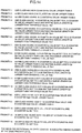
- the priority control process circuit 32 outputs 1 cell according to the priority level shown in Fig. 14.
- the CBR class, rt-VBR class and nrt-VBR class having the value of the N counter Nc, Ntv and Nv larger than 0 outputs the cells
- the value 1 is subtracted from the value of the N counter Nc, Ntv and Nv not set to 0 in the class outputting the cell.
- the ABR class and UBR class having the value of the W counter Wabr and Wubr larger than 0 outputs the cells
- the value 1 is subtracted from the value of the W counter Wabr and Wubr not set to 0 in the class outputting the cell.
- First cells are output from the band width demand class buffers CBR, rt-VBR and nrt-VBR for the CBR class, rt-VBR class and nrt-VBR class having the value of the N counter Nc, Ntv and Nv larger than 0 (Priority levels 1 to 3).
- Cells are output from the band width demand class buffers CBR, rt-VBR and nrt-VBR for the CBR class, rt-VBR class and nrt-VBR class having the value of the S counter Sc, Stv and Sv larger than 0 and the waiting queue length Qc, Qtv and Qv larger than the threshold value Thc1, Thtv1 and Thv1, respectively (Priority levels 4 to 6).
- Cells are output from the band width demand class buffers CBR, rt-VBR, nrt-VBR for the CBR class, rt-VBR class and nrt-VBR class having the value of the S counter Sc, Stv and Sv larger than 0 and the waiting queue length Qc, Qtv and Qv smaller than the threshold value Thc1, Thtv1 and Thv1, respectively (Priority levels 7 to 9).
- Cells are output from the band width demand class buffers CBR, rt-VBR and nrt-VBR for the CBR class, rt-VBR class and nrt-VBR class having the value of the S counter Sc, Stv and Sv set to 0 and the waiting queue length Qc, Qtv and Qv larger than the second threshold value Thc2, Thtv2 and Thv2, respectively (Priority levels 10 to 12).
- the cells stored in the best effort transfer demand class buffers ABR and UBR for the ABR class and the UBR class are output to the output channel 3 through the weighted rotational priority control (Priority level 13).
- the cells stored in the band width demand class buffers CBR, rt-VBR and nrt-VBR for the CBR class, rt-VBR class and nrt-VBR class having both values of the N counter Nc, Ntv and Nv and the S counter Sc, Stv and Sv set to 0 are output to the output channel 3 (Priority levels 14 to 16).
- the higher priority class buffer preferentially outputs the cell.
- the higher priority is given to the CBR class, rt-VBR class and nrt-VBR class having the value of the S counter Sc, Stv and Sv set to 0 and the waiting queue length Qc, Qtv and Qv larger than the second threshold value Thc2, Thtv2 and Thv2, respectively over the ABR class and the UBR class using the remained band width.
- the remained band width is available for the band width demand class. Therefore communication quality of the band width demand class having the unexpected traffic can be guaranteed to a certain extent without degrading the communication quality of other band width demand classes.
- the priority level shown in Fig. 15 can be used in place of those shown in Fig. 14 for preventing the higher priority class from giving an adverse effect on the lower priority class.
- the present invention is provided with a call reception control circuit for setting a guaranteed band width represented by the number of cells per certain time required to be output for assuring the communication quality of the band width demand class in the N counter for the respective band width demand classes at a certain time interval and a priority control process circuit for outputting cells stored in the band width demand class buffers for the respective band width demand classes according to the priority levels giving a priority to the band width demand class having the value of the N counter not set to 0 over the band width demand class having the value of the N counter set to 0 to the output channel. Even if an abnormal traffic is generated in a certain band width demand class, other band width demand classes are allowed to output the number of cells set in the N counter required for assuring the communication quality. In spite of the abnormal traffic generated in the certain band width demand class, the present invention allows the rest of the band width demand classes to keep the communication quality.
- the present invention is provided with a call reception control circuit for setting the guaranteed band width in the N counter of the respective band width demand classes as well as setting the value defined by the ratio of each W counter in the best effort classes to use the remained band width and a priority control process circuit for outputting cells stored in the respective band width demand class buffers and best effort transfer demand class buffers according to the priority levels giving a priority to the band width demand class having the value of the N counter not set to 0 over the band width demand classes and the best effort classes having the value of the N counter set to 0.
- the ATM exchange system accommodating calls of the band width demand classes and best effort classes, even if the abnormal traffic is generated in a certain band width demand class, communication quality of the rest of the band width demand classes can be protected from being deteriorated.
- the present invention is provided with a priority control process circuit for outputting cells stored in the band width demand class buffers and best effort transfer demand class buffers according to the priority level giving a higher priority to the band width demand class having the value of the S counter containing the value of unused guaranteed band width not set to 0 over the band width demand class and best effort class having the value of the S counter set to 0.
- the communication quality of the band width demand class can be kept. Therefore the number of calls for reception and the ratio of using the output channel for the band width demand class can be increased.
- band width demand classes at the same priority level are weighted rotational priority controlled by using the guaranteed band width of the respective band width demand class as the weight, thus further improving the delay characteristic.
- the present invention outputs cells to the output channel according to the priority level giving a priority to the band width demand class having the value of the S counter not set to 0 and the number of cells stored in its buffer equal to or larger than the first threshold value over the band width demand classes and best effort classes having the value of the S counter not set to 0 and the number of cells stored in the band width demand class buffer smaller than the first threshold value. Therefore the abnormal traffic generated in a certain band width demand class never gives an adverse effect on the other band width demand classes, as well as guaranteeing the communication quality of the band width demand class having the abnormality in the traffic.
- the present invention outputs cells stored in the respective band width demand class buffers and the best effort transfer demand class buffers according to the priority level giving a priority to the band width demand class having the value of the S counter set to 0 and the number of cells stored in the band width demand class buffer equal to or larger than the second threshold value over the best effort class.
- the band width demand class is allowed to use the remained band width.
- the band width demand class having abnormality in the traffic is able to keep its communication quality to a certain extent without giving an adverse effect on the communication quality of any other band width demand classes.
Landscapes
- Engineering & Computer Science (AREA)
- Computer Networks & Wireless Communication (AREA)
- Signal Processing (AREA)
- Quality & Reliability (AREA)
- Data Exchanges In Wide-Area Networks (AREA)
Applications Claiming Priority (3)
| Application Number | Priority Date | Filing Date | Title |
|---|---|---|---|
| JP32618395 | 1995-10-31 | ||
| JP32618395A JP2833555B2 (ja) | 1995-10-31 | 1995-10-31 | 優先制御方式 |
| JP326183/95 | 1995-10-31 |
Publications (3)
| Publication Number | Publication Date |
|---|---|
| EP0772325A2 true EP0772325A2 (fr) | 1997-05-07 |
| EP0772325A3 EP0772325A3 (fr) | 1998-05-06 |
| EP0772325B1 EP0772325B1 (fr) | 2003-09-10 |
Family
ID=18184969
Family Applications (1)
| Application Number | Title | Priority Date | Filing Date |
|---|---|---|---|
| EP19960117447 Expired - Lifetime EP0772325B1 (fr) | 1995-10-31 | 1996-10-30 | Système de commutation ATM et méthode de contrôle de priorité |
Country Status (5)
| Country | Link |
|---|---|
| US (1) | US6104698A (fr) |
| EP (1) | EP0772325B1 (fr) |
| JP (1) | JP2833555B2 (fr) |
| CA (1) | CA2189182C (fr) |
| DE (1) | DE69629890T2 (fr) |
Cited By (4)
| Publication number | Priority date | Publication date | Assignee | Title |
|---|---|---|---|---|
| FR2770070A1 (fr) * | 1997-10-20 | 1999-04-23 | Thomson Csf | Procede de controle de flux au sein d'un commutateur atm a architecture repartie |
| EP0942557A1 (fr) * | 1998-03-13 | 1999-09-15 | Pce | Méthode de multiplexage pour système de communication de type ATM |
| RU2213424C1 (ru) * | 2002-04-24 | 2003-09-27 | Военный университет связи | Устройство приема и обработки информации |
| RU2224375C2 (ru) * | 2001-07-30 | 2004-02-20 | Федеральное государственное унитарное предприятие Ростовский-на-Дону научно-исследовательский институт радиосвязи | Многофункциональная система приема, демодуляции и обработки сигналов i-iv уровней иерархического уплотнения |
Families Citing this family (17)
| Publication number | Priority date | Publication date | Assignee | Title |
|---|---|---|---|---|
| US6094435A (en) * | 1997-06-30 | 2000-07-25 | Sun Microsystems, Inc. | System and method for a quality of service in a multi-layer network element |
| US6421348B1 (en) * | 1998-07-01 | 2002-07-16 | National Semiconductor Corporation | High-speed network switch bus |
| US7154896B1 (en) * | 1998-07-24 | 2006-12-26 | Ericsson, Ab | ATM traffic having unknown characteristics including traffic with weighted priorities and traffic without weighted priorities |
| JP3075267B2 (ja) | 1998-09-02 | 2000-08-14 | 日本電気株式会社 | Atmセルバッファ読出し制御装置及び制御方法 |
| US6522653B1 (en) * | 1998-09-23 | 2003-02-18 | Nokia Telecommunications Oy | Use of priorities defined by a customer in a SIMA network |
| US6728272B1 (en) | 1998-12-30 | 2004-04-27 | At&T Corp. | Method and apparatus for transporting private line traffic over an ATM network |
| US6735191B1 (en) | 1998-12-30 | 2004-05-11 | At&T Corp. | Method and apparatus for transporting TDM voice traffic over an ATM network |
| JP3407696B2 (ja) | 1999-07-13 | 2003-05-19 | 日本電気株式会社 | Atm交換機および呼受付処理方法 |
| US6868461B1 (en) * | 2000-07-19 | 2005-03-15 | Mindspeed Technologies, Inc. | Link layer controller that provides a memory status signal to a network layer system in a communication device |
| JP4754683B2 (ja) * | 2000-11-22 | 2011-08-24 | 三菱電機株式会社 | 無線アクセスシステムおよび無線アクセス方法 |
| FI20045213A0 (fi) * | 2004-06-09 | 2004-06-09 | Nokia Corp | Lähetyksen ohjausmenetelmä, verkkoelementti, tukiasema ja radioverkko-ohjain |
| JP4454635B2 (ja) * | 2004-11-29 | 2010-04-21 | シャープ株式会社 | 帯域割り当て方法、帯域割り当てプログラム及びプログラム記録媒体 |
| US7738375B1 (en) * | 2005-08-19 | 2010-06-15 | Juniper Networks, Inc. | Shared shaping of network traffic |
| US20070058557A1 (en) * | 2005-09-15 | 2007-03-15 | Interdigital Technology Corporation | Method and apparatus for scheduling data transmissions based on a traffic data pattern model |
| JP2011250310A (ja) * | 2010-05-28 | 2011-12-08 | Mitsubishi Electric Corp | 通信制御装置及び通信制御方法 |
| JP5218690B2 (ja) * | 2012-05-18 | 2013-06-26 | 株式会社日立製作所 | 通信装置 |
| CN107038025B (zh) * | 2016-09-28 | 2020-04-07 | 阿里巴巴集团控股有限公司 | 基于soa架构的系统调用方法及装置 |
Family Cites Families (12)
| Publication number | Priority date | Publication date | Assignee | Title |
|---|---|---|---|---|
| US5153877A (en) * | 1989-04-21 | 1992-10-06 | Kabushiki Kaisha Toshiba | Packet network with communication resource allocation and call set up control of higher quality of service |
| JPH04257145A (ja) * | 1991-02-12 | 1992-09-11 | Hitachi Ltd | パケット流量制御方法およびパケット交換システム |
| US5509001A (en) * | 1991-10-18 | 1996-04-16 | Fujitsu Limited | Apparatus and method for controlling cells input to ATM network |
| SE515178C2 (sv) * | 1992-03-20 | 2001-06-25 | Ericsson Telefon Ab L M | Förfaranden och anordningar för prioritering vid bufferthantering i paketnät |
| JP2968648B2 (ja) * | 1992-08-05 | 1999-10-25 | 日本電気株式会社 | Atm通信網における優先制御方式 |
| US5696764A (en) * | 1993-07-21 | 1997-12-09 | Fujitsu Limited | ATM exchange for monitoring congestion and allocating and transmitting bandwidth-guaranteed and non-bandwidth-guaranteed connection calls |
| JPH0766820A (ja) * | 1993-08-24 | 1995-03-10 | Matsushita Electric Ind Co Ltd | フロー制御方式 |
| KR960003783B1 (ko) * | 1993-11-06 | 1996-03-22 | 한국전기통신공사 | 광대역 종합정보통신망 가입자 액세스 장치의 비동기 전달방식(atm) 다중화 처리 장치 및 방법 |
| JPH07183888A (ja) * | 1993-12-24 | 1995-07-21 | Fujitsu Ltd | Atm多重化制御方式 |
| JP3354689B2 (ja) * | 1994-02-28 | 2002-12-09 | 富士通株式会社 | Atm交換機、交換機及びそのスイッチングパス設定方法 |
| JP2928452B2 (ja) * | 1994-03-17 | 1999-08-03 | 富士通株式会社 | Atm交換機及びatm交換機における呼受付け装置及び呼受付け方法 |
| JP2922119B2 (ja) * | 1994-09-01 | 1999-07-19 | 沖電気工業株式会社 | 帯域規制装置及びパケット通信装置 |
-
1995
- 1995-10-31 JP JP32618395A patent/JP2833555B2/ja not_active Expired - Fee Related
-
1996
- 1996-10-30 DE DE1996629890 patent/DE69629890T2/de not_active Expired - Lifetime
- 1996-10-30 US US08/739,173 patent/US6104698A/en not_active Expired - Lifetime
- 1996-10-30 EP EP19960117447 patent/EP0772325B1/fr not_active Expired - Lifetime
- 1996-10-30 CA CA 2189182 patent/CA2189182C/fr not_active Expired - Lifetime
Non-Patent Citations (1)
| Title |
|---|
| None |
Cited By (7)
| Publication number | Priority date | Publication date | Assignee | Title |
|---|---|---|---|---|
| FR2770070A1 (fr) * | 1997-10-20 | 1999-04-23 | Thomson Csf | Procede de controle de flux au sein d'un commutateur atm a architecture repartie |
| EP0912018A1 (fr) * | 1997-10-20 | 1999-04-28 | Thomson-Csf | Procédé de contrÔle de flux au sein d'un commutateur ATM à architecture répartie |
| US6606302B2 (en) | 1997-10-20 | 2003-08-12 | Thomson-Csf | Method for the control of flows within an ATM switch with distributed architecture |
| USRE41970E1 (en) | 1997-10-20 | 2010-11-30 | Michel Delattre | Method for the control of flows within an ATM switch with distributed architecture |
| EP0942557A1 (fr) * | 1998-03-13 | 1999-09-15 | Pce | Méthode de multiplexage pour système de communication de type ATM |
| RU2224375C2 (ru) * | 2001-07-30 | 2004-02-20 | Федеральное государственное унитарное предприятие Ростовский-на-Дону научно-исследовательский институт радиосвязи | Многофункциональная система приема, демодуляции и обработки сигналов i-iv уровней иерархического уплотнения |
| RU2213424C1 (ru) * | 2002-04-24 | 2003-09-27 | Военный университет связи | Устройство приема и обработки информации |
Also Published As
| Publication number | Publication date |
|---|---|
| EP0772325A3 (fr) | 1998-05-06 |
| DE69629890T2 (de) | 2004-07-15 |
| DE69629890D1 (de) | 2003-10-16 |
| CA2189182A1 (fr) | 1997-05-01 |
| CA2189182C (fr) | 2002-01-08 |
| JPH09130400A (ja) | 1997-05-16 |
| EP0772325B1 (fr) | 2003-09-10 |
| US6104698A (en) | 2000-08-15 |
| JP2833555B2 (ja) | 1998-12-09 |
Similar Documents
| Publication | Publication Date | Title |
|---|---|---|
| US6104698A (en) | Asynchronous transfer mode exchange system and priority control method | |
| US6021116A (en) | Method and apparatus for controlling data transfer rate using virtual queues in asynchronous transfer mode networks | |
| EP0473188B1 (fr) | Méthode de commande pour la transmission de données dans un réseau ATM avec perte de cellules selon leur niveau de priorité | |
| US6259696B1 (en) | ATM switch and congestion control method | |
| EP0673138B1 (fr) | Méthode de gestion d'admission de connections pour un réseau ATM | |
| CA2118471C (fr) | Cadre de controle du trafic utilisant les parametres d'utilisation pour reseaux mta | |
| US5983278A (en) | Low-loss, fair bandwidth allocation flow control in a packet switch | |
| EP0755594B1 (fr) | Dispositif de comptage de deuxieme ordre pour protection contre les erreurs et son procede a des fins de gestion du trafic dans les reseaux cellulaires | |
| CA2249556C (fr) | Noeud de reseau avec tampon commun a de multiples connexions et largeur de bande minimale pour chaque connexion | |
| US6980516B1 (en) | Soft, prioritized early packet discard system | |
| EP0508378A2 (fr) | Méthode et système pour la surveillance de débit de paquets dans un réseau de paquets | |
| US5905711A (en) | Method and apparatus for controlling data transfer rates using marking threshold in asynchronous transfer mode networks | |
| US6298042B1 (en) | Packet switching apparatus adapted to control allowed transmission rate in packet switching network, and method of controlling allowed transmission rate | |
| EP0973304A2 (fr) | Dispositif et méthode de gestion de largeur de bande | |
| EP1031253B1 (fr) | Procédé de gestion des mémoires tampons | |
| US6560195B1 (en) | Method and apparatus for leaky bucket based out-bound shaping in an ATM scheduler | |
| EP1232609B1 (fr) | Partage de la capacite de liaison en vue de l'optimisation du blocage du debit de traitement | |
| US6430157B1 (en) | Communication controlling apparatus | |
| US7133932B2 (en) | Scheduling system using packet FIFOs and cell FIFOs for converting IP packets to ATM cells | |
| EP0979022B1 (fr) | Procédé et dispositif pour le fonctionnement d'un algorithme d'indication simple du débit explicite | |
| JP3051101B2 (ja) | セルバッファ装置および選択的atmセル廃棄方法 | |
| US5905710A (en) | Method for controlling a re-emission interval in an asynchronous transfer mode interval controller | |
| US7012923B2 (en) | Method for allocating a bandwidth between network terminals in a communication network and network including a medium access controller for performing such a method | |
| US7477596B1 (en) | Policing engine providing dynamic adjustment of peak and sustained data cell rates and efficient transfer of AAL5 cells | |
| JP3203610B2 (ja) | セル流制御装置 |
Legal Events
| Date | Code | Title | Description |
|---|---|---|---|
| PUAI | Public reference made under article 153(3) epc to a published international application that has entered the european phase |
Free format text: ORIGINAL CODE: 0009012 |
|
| AK | Designated contracting states |
Kind code of ref document: A2 Designated state(s): DE FR SE |
|
| PUAL | Search report despatched |
Free format text: ORIGINAL CODE: 0009013 |
|
| AK | Designated contracting states |
Kind code of ref document: A3 Designated state(s): DE FR SE |
|
| 17P | Request for examination filed |
Effective date: 19980401 |
|
| 17Q | First examination report despatched |
Effective date: 20020117 |
|
| GRAH | Despatch of communication of intention to grant a patent |
Free format text: ORIGINAL CODE: EPIDOS IGRA |
|
| GRAS | Grant fee paid |
Free format text: ORIGINAL CODE: EPIDOSNIGR3 |
|
| GRAA | (expected) grant |
Free format text: ORIGINAL CODE: 0009210 |
|
| AK | Designated contracting states |
Kind code of ref document: B1 Designated state(s): DE FR SE |
|
| REG | Reference to a national code |
Ref country code: SE Ref legal event code: TRGR |
|
| REF | Corresponds to: |
Ref document number: 69629890 Country of ref document: DE Date of ref document: 20031016 Kind code of ref document: P |
|
| ET | Fr: translation filed | ||
| PLBE | No opposition filed within time limit |
Free format text: ORIGINAL CODE: 0009261 |
|
| STAA | Information on the status of an ep patent application or granted ep patent |
Free format text: STATUS: NO OPPOSITION FILED WITHIN TIME LIMIT |
|
| 26N | No opposition filed |
Effective date: 20040614 |
|
| REG | Reference to a national code |
Ref country code: FR Ref legal event code: TP |
|
| REG | Reference to a national code |
Ref country code: FR Ref legal event code: PLFP Year of fee payment: 20 |
|
| PGFP | Annual fee paid to national office [announced via postgrant information from national office to epo] |
Ref country code: FR Payment date: 20150908 Year of fee payment: 20 |
|
| PGFP | Annual fee paid to national office [announced via postgrant information from national office to epo] |
Ref country code: DE Payment date: 20151028 Year of fee payment: 20 |
|
| PGFP | Annual fee paid to national office [announced via postgrant information from national office to epo] |
Ref country code: SE Payment date: 20151013 Year of fee payment: 20 |
|
| REG | Reference to a national code |
Ref country code: DE Ref legal event code: R071 Ref document number: 69629890 Country of ref document: DE |
|
| REG | Reference to a national code |
Ref country code: SE Ref legal event code: EUG |