EP0772904B1 - Dispositif d'alimentation en courant avec deux tensions de sortie - Google Patents
Dispositif d'alimentation en courant avec deux tensions de sortie Download PDFInfo
- Publication number
- EP0772904B1 EP0772904B1 EP96905743A EP96905743A EP0772904B1 EP 0772904 B1 EP0772904 B1 EP 0772904B1 EP 96905743 A EP96905743 A EP 96905743A EP 96905743 A EP96905743 A EP 96905743A EP 0772904 B1 EP0772904 B1 EP 0772904B1
- Authority
- EP
- European Patent Office
- Prior art keywords
- voltage
- generator
- additional
- connection
- voltage supply
- Prior art date
- Legal status (The legal status is an assumption and is not a legal conclusion. Google has not performed a legal analysis and makes no representation as to the accuracy of the status listed.)
- Expired - Lifetime
Links
- 238000004804 winding Methods 0.000 claims description 29
- 230000005284 excitation Effects 0.000 claims description 18
- 230000001105 regulatory effect Effects 0.000 claims description 16
- 239000004065 semiconductor Substances 0.000 claims description 12
- 238000010079 rubber tapping Methods 0.000 claims description 6
- 238000011156 evaluation Methods 0.000 claims 1
- 206010001497 Agitation Diseases 0.000 description 1
- 230000004913 activation Effects 0.000 description 1
- 230000001276 controlling effect Effects 0.000 description 1
- 238000001514 detection method Methods 0.000 description 1
- 230000006870 function Effects 0.000 description 1
- 238000010438 heat treatment Methods 0.000 description 1
- 238000000926 separation method Methods 0.000 description 1
- 230000007704 transition Effects 0.000 description 1
- 238000005303 weighing Methods 0.000 description 1
Images



Classifications
-
- H—ELECTRICITY
- H02—GENERATION; CONVERSION OR DISTRIBUTION OF ELECTRIC POWER
- H02P—CONTROL OR REGULATION OF ELECTRIC MOTORS, ELECTRIC GENERATORS OR DYNAMO-ELECTRIC CONVERTERS; CONTROLLING TRANSFORMERS, REACTORS OR CHOKE COILS
- H02P9/00—Arrangements for controlling electric generators for the purpose of obtaining a desired output
-
- H—ELECTRICITY
- H02—GENERATION; CONVERSION OR DISTRIBUTION OF ELECTRIC POWER
- H02P—CONTROL OR REGULATION OF ELECTRIC MOTORS, ELECTRIC GENERATORS OR DYNAMO-ELECTRIC CONVERTERS; CONTROLLING TRANSFORMERS, REACTORS OR CHOKE COILS
- H02P9/00—Arrangements for controlling electric generators for the purpose of obtaining a desired output
- H02P9/14—Arrangements for controlling electric generators for the purpose of obtaining a desired output by variation of field
- H02P9/26—Arrangements for controlling electric generators for the purpose of obtaining a desired output by variation of field using discharge tubes or semiconductor devices
- H02P9/30—Arrangements for controlling electric generators for the purpose of obtaining a desired output by variation of field using discharge tubes or semiconductor devices using semiconductor devices
- H02P9/305—Arrangements for controlling electric generators for the purpose of obtaining a desired output by variation of field using discharge tubes or semiconductor devices using semiconductor devices controlling voltage
- H02P9/307—Arrangements for controlling electric generators for the purpose of obtaining a desired output by variation of field using discharge tubes or semiconductor devices using semiconductor devices controlling voltage more than one voltage output
-
- H—ELECTRICITY
- H02—GENERATION; CONVERSION OR DISTRIBUTION OF ELECTRIC POWER
- H02M—APPARATUS FOR CONVERSION BETWEEN AC AND AC, BETWEEN AC AND DC, OR BETWEEN DC AND DC, AND FOR USE WITH MAINS OR SIMILAR POWER SUPPLY SYSTEMS; CONVERSION OF DC OR AC INPUT POWER INTO SURGE OUTPUT POWER; CONTROL OR REGULATION THEREOF
- H02M1/00—Details of apparatus for conversion
- H02M1/0083—Converters characterised by their input or output configuration
- H02M1/0085—Partially controlled bridges
Definitions
- the invention relates to a device for power supply in a motor vehicle electrical system, according to the genus of Main claim.
- DE 42 26 311 A1 describes a three-phase generator for a Motor vehicle known, its winding in a star connection are switched. By tapping the star points a provided additional output voltage, which is about is half the normal vehicle electrical system voltage.
- This known generator has in addition to the usual Rectifier bridge from which the vehicle electrical system voltage can be tapped is, an additional rectifier bridge that with the star point is connected and the second output voltage supplies. A regulation of the load current of the generator does not happen.
- the inventive device for power supply in a motor vehicle electrical system with the features of the claim 1 have the advantage over the known that several Tensions are available and at the same time a Regulation takes place, which is independent of the generator actually present load in an operating state holds, in which an optimal power output can take place.
- This advantage is achieved by using a generator with a second or more outputs is used and between the generator stand and the additional terminals further rectifier arrangements are inserted and additional ones Means are provided with the help of which the load current of the generator can be influenced. Do include these additional means controllable circuit breakers that either replace part of the rectifier bridge or these are downstream.
- the regulation of the excitation current can affect either the Stator voltage, the B + voltage or the B2 + voltage or Bx + voltage and is used in the usual way by the voltage regulator carried out.
- the invention can be advantageously used for generators multiple stars in parallel with star or delta connections or Delta connections or combinations of star and Use delta connection.
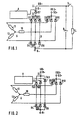
- FIG. 1 shows a first one Embodiment in the usual rectifier bridges be used and an additional controlled switching element to limit the load current of the generator is.
- An exemplary embodiment is shown in FIG. where the positive three-phase bridge can be controlled by Switching elements is replaced.
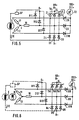
- Figure 3 is an embodiment shown, largely that of Figure 1 corresponds, but additionally has a regulated output.
- An exemplary embodiment is given in FIG which each generator winding has two connections.
- Figure 5 shows an embodiment of an electrically excited Generator with single-phase load current control and Figure 6 a Example with a permanently excited generator that is similar to that of the Figure 2 corresponds, but additionally a regulated output having.
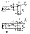
- FIGS. 7 to 9 show further exemplary embodiments for an electrically excited generator, whereby in Figure 7 a star center tap with a downstream additional diode and a power controller is available.
- Figures 10 and 11 are examples of Multiple taps in star and delta connection specified.
- the stator windings 10, 11, 12 are in the usual way connected to the diode bridge D.
- the diodes D1, D2, D3 are usually as plus diodes, the diodes D4, D5, D6 as Denoted minus diodes.
- the negative connection of the diode bridge D is labeled B-, the other side of the diode bridge D leads via a controllable semiconductor power switch D7 to terminal B +, where voltage UB + occurs.
- the semiconductor power switch D7 is controlled by means of the control device A.
- Another diode bridge with diodes D8, D9, D10 is available with the stator windings 10, 11, 12 and the center points the diode bridge D in connection and leads to the additional Connection B + 2, at which the voltage UB2 + occurs.
- the positive half bridge of the rectifier bridge is replaced through a controlled rectifier bridge, for example Thyristors Th1, Th2, Th3 comprises that of the Control A can be controlled to limit the load current IL.
- FIG. 3 shows a further exemplary embodiment, that draws a permanently excited (M) or dashed line, one, self or externally excited, an excitation winding E having generator with regulated additional output with regulated Voltage U2 + and external circuit breaker or Linear controller includes.
- M permanently excited
- FIG. 3 which relates to an externally excited generator, the excitation current bridge with the excitation diodes D11, D12, D13 shown. These excitation current diodes lead to Connection D + and via this via the voltage regulator SP and the excitation winding E to the generator connection B-.
- the current through the excitation winding IE is using the voltage regulator SP regulated in a known manner so that the output voltage of the generator remains approximately constant.
- the load current limitation is used in the embodiment according to Figure 3 shows the transistor T1, which with the aid of the control A is controllable with the help of a further transistor T2 can be on the cathode side of the additional diodes D8, D9, D10 generate an additional regulated output voltage UB2 +, the control of the transistor T2 depending on Load so that T2 acts as a linear regulator or switching regulator is working.
- the transistor T2 can otherwise be omitted, provided that it is a generator a self or externally excited generator with excitation current control is used.
- FIG 4 an embodiment is shown in which the stator windings 10, 11, 12 each have a second connection exhibit (which can also exist several times) and this to decouple the additional voltage across the Diodes D8, D9, D10 is used.
- This circuit arrangement which in turn is for a permanently excited generator is suitable if the transistor T2 is present or for a self-excited or externally excited generator (dashed) with excitation current control, the transistor T2 being omitted can, provides a second generator output voltage regulated voltage UB2 +, which is higher than that tapped at B + Voltage, where the voltage level from the tap point depends.
- the embodiments shown in Figures 5 to 9 only differ from those already described in that the one or more diodes by a Thyristor to be replaced.
- the thyristors are with Th4 - Th7 called.
- the power components shown can be 1-, 2- or 3-phase controlled half or Represent full bridges. Additional outputs are as 1-, 2- or 3-phase controlled / uncontrolled half or Full bridge can be represented with different power components.
- Figure 9 is the additional connection B2 + via a rectifier bridge D15 to D20 in connection with the generator, as well as a load current limiting semiconductor power component T2.
- All of the exemplary embodiments shown in FIGS. 1-9 have at least one controllable component in the main rectifier bridge or between the generator and the connection B +, over which the load current IL of the generator can be influenced. Furthermore, all embodiments common that in addition to the usual connection B +, to from which a first voltage UB + can be tapped, at least one second connection B2 + is present, at which a second voltage UB2 + can be tapped, depending on the design of these second voltage is a DC voltage or an AC voltage is. Furthermore, this voltage can be the same as usual Electrical system voltage, or higher than this or also have lower values, depending on the connection to the stator windings 10, 11, 12 or the power controller type (Linear or switching regulator).
- the generator can be connected to the additional outputs Deliver direct current.
- the additional Output terminal or the additional output terminals can there is a separation between the power supply systems be, by suitable control of the controllable components, for example thyristors, it is possible to use one of the Equip outputs with higher priority, so that, for example a loading priority for a start memory is feasible.
- the generators are regulated in such a way that self and externally excited generators the output voltage at terminal B + by interrupting the excitation current, in a conventional manner using a voltage regulator he follows.
- a distinction is made, however, in the regulation of the generator between full load operation and part load operation.
- Full load operation in which the voltage level of the generator of the amount of the required load current is determined, If the load is too high, the terminal voltage may drop too far, so that for the supply of individual consumers Problems or should be designed so that even with a significantly lower vehicle electrical system voltage work reliably.
- the load current is limited by activation the circuit breaker between the rectifier bridge and the connection B +.
- the output voltage at terminal B2 + can either be with
- the transistor T2 can be regulated, it can also be a unregulated voltage are given. With a conventional one Excitation current control can be omitted transistor T2 and a regulated output voltage is still obtained.
- the output voltage either limited by the previous voltage regulator or for example with permanently excited generators with the help an (additional) power component attached to the outputs limited.
- the control of the controlled Rectifier, the thyristors or semiconductor power devices can be in block, phase control or Linear operation take place.
- a possibly existing DC regulator can be operated continuously.
- the generator can be continuously operated in one area that corresponds to the transition to full load. This ensures that the generator is under delivers the maximum possible performance in all circumstances, which is obtained at the partial load / full load limit.
- the detection of the load on the generator can be measured its output voltage, by measuring the load current or excitation current duty cycle etc.
- a bridge can also be different Have switching elements.
- the rectifier bridges can be used as semi-controlled Diodes or Zener diodes can be designed or as fully controlled Bridges that provide full transitional protection guarantee.
- Every connection is included to provide a power controller so that at the connections no overvoltage can occur.
- These power controllers can also be used in addition to the voltage limiting function Load current control can be used at generator best point.
Landscapes
- Engineering & Computer Science (AREA)
- Power Engineering (AREA)
- Control Of Eletrric Generators (AREA)
- Synchronous Machinery (AREA)
Claims (13)
- Dispositif d'alimentation en tension dans un circuit de bord d'un véhicule, comportant un générateur (G) fournissant un courant de charge (IL), dont la tension de sortie (UB+) est réglée de telle sorte qu'elle est à peu près constante, comportant un premier ensemble de redresseurs (D1-D6) connecté après le générateur (G) et qui fournit une tension (UB+) au niveau d'une première connexion (B+), comportant un deuxième ensemble de redresseurs (D8, D9, D10), par lequel peut être reçue une deuxième tension (UB2+) au niveau d'au moins une deuxième connexion (B2+),
caractérisé en ce que
des moyens supplémentaires sont prévus pour influencer le courant de charge (IL) du générateur (G) et comprennent au moins un élément semi-conducteur pouvant être commandé au moyen d'une commande (A). - Dispositif d'alimentation en tension selon la revendication 1,
caractérisé en ce que
les moyens supplémentaires permettant d'influencer le courant de charge sont des thyristors (Th1-Th7). - Dispositif de régulation de la tension selon la revendication 1 ou 2,
caractérisé en ce que
le générateur (G) est un générateur à auto-excitation ou à excitation indépendante, dont le courrant d'excitation est réglé au moyen d'un régulateur de tension (SP). - Dispositif de régulation de la tension selon la revendication 1, 2 ou 3,
caractérisé en ce que
les éléments semi-conducteurs pouvant être commandés forment un composant du pont de redressement principal et remplacent les redresseurs en pont correspondants. - Dispositif d'alimentation en tension selon l'une des revendications précédentes,
caractérisé en ce que
les composants semi-conducteurs pouvant être commandés sont présents en plus du pont de redressement principal et se trouvent entre les diodes plus et la connexion (B+). - Dispositif de régulation de la tension selon la revendication 5,
caractérisé en ce que
le composant semi-conducteur supplémentaire comprend au moins un thyristor (Th1-Th7) ou un transistor (T1, T2) ainsi qu'une commande (A). - Dispositif d'alimentation en tension selon l'une des revendications précédentes,
caractérisé en ce que
le pont de redressement principal est relié à respectivement une première connexion de l'enroulement du stator (10, 11, 12) du générateur (G), et la borne de tension supplémentaire (B2+) est reliée à la même connexion d'au moins l'un des enroulements du stator (10, 11, 12). - Dispositif d'alimentation en tension selon l'une des revendications précédentes,
caractérisé en ce que
les enroulements du stator (10, 11, 12) du générateur (G) forment un montage à point neutre, et le point neutre est relié à la borne de tension supplémentaire (B2+) par le biais d'un élément de redresseur. - Dispositif d'alimentation en tension selon l'une des revendications précédentes,
caractérisé en ce que
la régulation de la tension de sortie du générateur (G), en fonctionnement en charge partielle, s'effectue à l'aide du régulateur de tension (SP) et en fonctionnement en charge totale, une commande des éléments semi-conducteurs pouvant être commandés est déclenchée, afin de limiter le courant de charge (IL) du générateur (G), afin que le générateur (G) fonctionne dans la plage de travail la plus favorable. - Dispositif de régulation de la tension selon la revendication 8,
caractérisé en ce que
la reconnaissance de l'état de charge totale s'effectue par l'exploitation de la tension fournie par le générateur (G), du courant ou du facteur d'utilisation du courant d'excitation, et l'état de charge totale est détecté lorsque cette tension est inférieure à une valeur pouvant être prédéterminée. - Dispositif d'alimentation en tension en particulier selon l'une des revendications précédentes,
caractérisé en ce que
les enroulements du stator présentent des prises pour un nombre de spires pouvant être prédéterminé, qui conduisent à des bornes de tension supplémentaires (Bx+), au niveau desquelles peuvent être reçues les tensions (UBx+), dont la valeur dépend de la place de la prise. - Dispositif d'alimentation en tension selon l'une des revendications précédentes,
caractérisé en ce que
l'enroulement du stator (10, 11, 12) du générateur (G) est configuré en montage en étoile, en montage en triangle ou en tant que combinaison de montage en étoile et en triangle, et les prises d'enroulement sont présentes au niveau de chaque enroulement. - Dispositif d'alimentation en tension selon l'une des revendications précédentes,
caractérisé en ce que
d'autres spires sont reliées aux extrémités extérieures de l'enroulement et conduisent aux autres connexions (Bx+).
Applications Claiming Priority (3)
| Application Number | Priority Date | Filing Date | Title |
|---|---|---|---|
| DE19519298 | 1995-05-26 | ||
| DE19519298A DE19519298A1 (de) | 1995-05-26 | 1995-05-26 | Vorrichtung zur Spannungsversorgung mit zwei Ausgangsspannungen |
| PCT/DE1996/000473 WO1996037947A1 (fr) | 1995-05-26 | 1996-03-19 | Dispositif d'alimentation en courant avec deux tensions de sortie |
Publications (2)
| Publication Number | Publication Date |
|---|---|
| EP0772904A1 EP0772904A1 (fr) | 1997-05-14 |
| EP0772904B1 true EP0772904B1 (fr) | 2004-09-01 |
Family
ID=7762894
Family Applications (1)
| Application Number | Title | Priority Date | Filing Date |
|---|---|---|---|
| EP96905743A Expired - Lifetime EP0772904B1 (fr) | 1995-05-26 | 1996-03-19 | Dispositif d'alimentation en courant avec deux tensions de sortie |
Country Status (6)
| Country | Link |
|---|---|
| US (1) | US6049198A (fr) |
| EP (1) | EP0772904B1 (fr) |
| KR (1) | KR100426886B1 (fr) |
| DE (2) | DE19519298A1 (fr) |
| ES (1) | ES2227582T3 (fr) |
| WO (1) | WO1996037947A1 (fr) |
Families Citing this family (13)
| Publication number | Priority date | Publication date | Assignee | Title |
|---|---|---|---|---|
| DE19838973A1 (de) * | 1998-08-27 | 2000-03-02 | Bosch Gmbh Robert | Mehrspannungsbordnetz für ein Fahrzeug |
| US6912142B2 (en) | 2000-01-24 | 2005-06-28 | Massachusetts Institute Of Technology | Alternator control circuit and related techniques |
| US6239996B1 (en) * | 2000-01-24 | 2001-05-29 | Massachusetts Institute Of Technology | Dual output alternator system |
| DE10047287A1 (de) * | 2000-09-20 | 2002-04-04 | Bosch Gmbh Robert | Anordnung und Verfahren zum Erzeugen verschiedener Ausgangsspannungen mit einem Wechselstromgenerator |
| US6624618B2 (en) | 2001-01-25 | 2003-09-23 | Ford Global Technologies, Llc | System and method for vehicle voltage regulation |
| FR2835106B1 (fr) * | 2002-01-24 | 2004-09-03 | Peugeot Citroen Automobiles Sa | Systeme d'alimentation en energie electrique d'un vehicule automobile |
| US7084610B2 (en) * | 2004-01-06 | 2006-08-01 | Visteon Global Technologies, Inc. | Alternator rectifier |
| DE102005015658A1 (de) | 2005-04-06 | 2007-01-11 | Bayerische Motoren Werke Ag | Schalteinrichtung zur Verknüpfung verschiedener elektrischer Spannungsebenen in einem Kraftfahrzeug |
| ITMI20071432A1 (it) * | 2007-07-17 | 2009-01-18 | Ducati Energia Spa | Regolatore di tensione per magnetogeneratori a connessione configurabile degli avvolgimenti di fase |
| US8606444B2 (en) * | 2010-12-29 | 2013-12-10 | Caterpillar Inc. | Machine and power system with electrical energy storage device |
| JP5605336B2 (ja) * | 2011-08-31 | 2014-10-15 | 国産電機株式会社 | 電源装置 |
| DE102014222337B3 (de) * | 2014-10-31 | 2016-01-21 | Continental Teves Ag & Co. Ohg | Verfahren und Vorrichtung zur Steuerung eines fremderregten elektrischen Generators in einem Bordnetz eines Kraftfahrzeuges |
| DE102015219674A1 (de) * | 2015-10-12 | 2017-04-13 | Continental Automotive Gmbh | Fahrzeugbordnetz |
Family Cites Families (16)
| Publication number | Priority date | Publication date | Assignee | Title |
|---|---|---|---|---|
| DE1277990B (de) * | 1966-03-24 | 1968-09-19 | Bernhard Kirsch | Vorrichtung zur Konstanthaltung der Spannung bei Generatoren, die Ein- und Mehrphasenstrom abgeben |
| DE2650851A1 (de) * | 1976-11-06 | 1978-05-11 | Bosch Gmbh Robert | Stromversorgungseinrichtung fuer eine zweispannungsanlage in einem kraftfahrzeug |
| US4169992A (en) * | 1977-11-23 | 1979-10-02 | Bible Translations on Tape, Inc. | Feedback speed control of spring powered generator |
| DE2920101A1 (de) * | 1979-05-18 | 1980-11-27 | Bosch Gmbh Robert | Vorrichtung zur erregung von drehstromgeneratoren |
| DE3226426A1 (de) * | 1982-07-15 | 1984-01-19 | Robert Bosch Gmbh, 7000 Stuttgart | Spannungsregler fuer permanentfeldgenerator |
| ZA874089B (en) * | 1986-06-10 | 1987-12-30 | Stefanus Van Der Linde Hendrik | Electric power generator |
| US4692684A (en) * | 1986-09-17 | 1987-09-08 | General Motors Corporation | High/low DC voltage motor vehicle electrical system |
| DE3841610A1 (de) * | 1988-12-10 | 1990-06-13 | Bosch Gmbh Robert | Vorrichtung zur spannungsversorgung fuer ein kraftfahrzeug-bordnetz |
| DE3843163C2 (de) * | 1988-12-22 | 1998-09-24 | Bosch Gmbh Robert | Vorrichtung zur Regelung eines Fahrzeug-Drehstrom-Generators |
| JP2695458B2 (ja) * | 1989-02-14 | 1997-12-24 | 澤藤電機株式会社 | 個別給電可能な溶接用発電装置 |
| JP2526667B2 (ja) * | 1989-06-05 | 1996-08-21 | 三菱電機株式会社 | 充電発電装置 |
| DE69130465T2 (de) * | 1990-06-28 | 1999-06-02 | Denso Corp., Kariya, Aichi | Stromversorgungseinheit für ein Kraftfahrzeug |
| US5418401A (en) * | 1991-10-29 | 1995-05-23 | Mitsubishi Denki Kabushiki Kaisha | Power supply apparatus for a vehicle having batteries of different voltages which are charged according to alternator speed |
| US5214371A (en) * | 1991-12-04 | 1993-05-25 | General Motors Corporation | Voltage regulator for variable speed permanent magnet alternators |
| DE4226311A1 (de) * | 1992-08-08 | 1994-02-10 | Audi Ag | Drehstromgenerator |
| IT1257173B (it) * | 1992-10-28 | 1996-01-05 | Magneti Marelli Spa | Dispositivo per la regolazione della tensione per un generatore elettrico, in particolare un alternatore. |
-
1995
- 1995-05-26 DE DE19519298A patent/DE19519298A1/de not_active Ceased
-
1996
- 1996-03-19 DE DE59611072T patent/DE59611072D1/de not_active Expired - Fee Related
- 1996-03-19 WO PCT/DE1996/000473 patent/WO1996037947A1/fr not_active Ceased
- 1996-03-19 KR KR1019970700449A patent/KR100426886B1/ko not_active Expired - Fee Related
- 1996-03-19 EP EP96905743A patent/EP0772904B1/fr not_active Expired - Lifetime
- 1996-03-19 US US08/765,550 patent/US6049198A/en not_active Expired - Fee Related
- 1996-03-19 ES ES96905743T patent/ES2227582T3/es not_active Expired - Lifetime
Also Published As
| Publication number | Publication date |
|---|---|
| US6049198A (en) | 2000-04-11 |
| KR970705224A (ko) | 1997-09-06 |
| KR100426886B1 (ko) | 2004-06-23 |
| DE59611072D1 (de) | 2004-10-07 |
| WO1996037947A1 (fr) | 1996-11-28 |
| DE19519298A1 (de) | 1996-11-28 |
| ES2227582T3 (es) | 2005-04-01 |
| EP0772904A1 (fr) | 1997-05-14 |
Similar Documents
| Publication | Publication Date | Title |
|---|---|---|
| DE69615907T2 (de) | Stromgeneratorvorrichtung für Fahrzeuge | |
| EP0352304B1 (fr) | Circuit de bord de vehicule | |
| EP1042860B1 (fr) | Redresseur en pont commande a limiteur de tension | |
| DE69625119T2 (de) | Stromversorgungsanlage | |
| DE69614180T2 (de) | Fahrzeugenergieerzeugungssystem und Verfahren zu dessen Steuerung | |
| DE69216365T2 (de) | Stromversorgungsvorrichtung für ein Fahrzeug | |
| EP0772904B1 (fr) | Dispositif d'alimentation en courant avec deux tensions de sortie | |
| DE2600035A1 (de) | Stromgenerator | |
| DE102008023779A1 (de) | Generator mit hohem Wirkungsgrad | |
| DE10114075A1 (de) | Stromrichterschaltungsanordnung für Generatoren mit dynamisch veränderlicher Leistungsabgabe | |
| DE2650851A1 (de) | Stromversorgungseinrichtung fuer eine zweispannungsanlage in einem kraftfahrzeug | |
| DE10057259A1 (de) | Mehrspannungsbordnetz für ein Kraftfahrzeug | |
| WO2006021511A1 (fr) | Regulateur de tension a protection contre les surtensions | |
| DE19838296B4 (de) | Elektrisches Spannungsversorgungssystem | |
| DE19838973A1 (de) | Mehrspannungsbordnetz für ein Fahrzeug | |
| DE2811440A1 (de) | Elektrischer generator | |
| DE4226311A1 (de) | Drehstromgenerator | |
| EP1249066B1 (fr) | Appareil électrique comportant un motoeur électrique et un convertisseur à inductance | |
| DE3810870A1 (de) | Vorrichtung zum umformen von elektrischer energie | |
| DE3035819C2 (fr) | ||
| EP0802867B1 (fr) | Commande de la consommation de courant de plusieurs consommateurs de courant dans un vehicule a moteur | |
| DE3432127A1 (de) | Gleichstromgenerator | |
| DE102015120658A1 (de) | Verfahren und Vorrichtung zum Steuern eines elektrischen oder elektronischen Schaltelements | |
| EP1849229B1 (fr) | Machine electrique | |
| DE4237843A1 (de) | Schaltungsanordnung zum Betreiben einer induktiven Last |
Legal Events
| Date | Code | Title | Description |
|---|---|---|---|
| PUAI | Public reference made under article 153(3) epc to a published international application that has entered the european phase |
Free format text: ORIGINAL CODE: 0009012 |
|
| AK | Designated contracting states |
Kind code of ref document: A1 Designated state(s): DE ES FR GB IT |
|
| 17P | Request for examination filed |
Effective date: 19970528 |
|
| 17Q | First examination report despatched |
Effective date: 20000105 |
|
| GRAP | Despatch of communication of intention to grant a patent |
Free format text: ORIGINAL CODE: EPIDOSNIGR1 |
|
| RIC1 | Information provided on ipc code assigned before grant |
Ipc: 7H 02P 9/30 A |
|
| RIC1 | Information provided on ipc code assigned before grant |
Ipc: 7H 02P 9/30 A |
|
| GRAS | Grant fee paid |
Free format text: ORIGINAL CODE: EPIDOSNIGR3 |
|
| GRAA | (expected) grant |
Free format text: ORIGINAL CODE: 0009210 |
|
| AK | Designated contracting states |
Kind code of ref document: B1 Designated state(s): DE ES FR GB IT |
|
| REG | Reference to a national code |
Ref country code: GB Ref legal event code: FG4D Free format text: NOT ENGLISH |
|
| REF | Corresponds to: |
Ref document number: 59611072 Country of ref document: DE Date of ref document: 20041007 Kind code of ref document: P |
|
| GBT | Gb: translation of ep patent filed (gb section 77(6)(a)/1977) | ||
| REG | Reference to a national code |
Ref country code: ES Ref legal event code: FG2A Ref document number: 2227582 Country of ref document: ES Kind code of ref document: T3 |
|
| PLBE | No opposition filed within time limit |
Free format text: ORIGINAL CODE: 0009261 |
|
| STAA | Information on the status of an ep patent application or granted ep patent |
Free format text: STATUS: NO OPPOSITION FILED WITHIN TIME LIMIT |
|
| ET | Fr: translation filed | ||
| 26N | No opposition filed |
Effective date: 20050602 |
|
| PGFP | Annual fee paid to national office [announced via postgrant information from national office to epo] |
Ref country code: ES Payment date: 20060320 Year of fee payment: 11 |
|
| GBPC | Gb: european patent ceased through non-payment of renewal fee |
Effective date: 20070319 |
|
| PG25 | Lapsed in a contracting state [announced via postgrant information from national office to epo] |
Ref country code: GB Free format text: LAPSE BECAUSE OF NON-PAYMENT OF DUE FEES Effective date: 20070319 |
|
| REG | Reference to a national code |
Ref country code: ES Ref legal event code: FD2A Effective date: 20070320 |
|
| PG25 | Lapsed in a contracting state [announced via postgrant information from national office to epo] |
Ref country code: ES Free format text: LAPSE BECAUSE OF NON-PAYMENT OF DUE FEES Effective date: 20070320 |
|
| PGFP | Annual fee paid to national office [announced via postgrant information from national office to epo] |
Ref country code: GB Payment date: 20060323 Year of fee payment: 11 |
|
| PGFP | Annual fee paid to national office [announced via postgrant information from national office to epo] |
Ref country code: IT Payment date: 20090326 Year of fee payment: 14 Ref country code: DE Payment date: 20090526 Year of fee payment: 14 |
|
| PGFP | Annual fee paid to national office [announced via postgrant information from national office to epo] |
Ref country code: FR Payment date: 20090318 Year of fee payment: 14 |
|
| REG | Reference to a national code |
Ref country code: FR Ref legal event code: ST Effective date: 20101130 |
|
| PG25 | Lapsed in a contracting state [announced via postgrant information from national office to epo] |
Ref country code: FR Free format text: LAPSE BECAUSE OF NON-PAYMENT OF DUE FEES Effective date: 20100331 |
|
| PG25 | Lapsed in a contracting state [announced via postgrant information from national office to epo] |
Ref country code: DE Free format text: LAPSE BECAUSE OF NON-PAYMENT OF DUE FEES Effective date: 20101001 |
|
| PG25 | Lapsed in a contracting state [announced via postgrant information from national office to epo] |
Ref country code: IT Free format text: LAPSE BECAUSE OF NON-PAYMENT OF DUE FEES Effective date: 20100319 |