EP0773053A1 - Filtre pour liquide refluant dans un réservoir fermé - Google Patents
Filtre pour liquide refluant dans un réservoir fermé Download PDFInfo
- Publication number
- EP0773053A1 EP0773053A1 EP96117662A EP96117662A EP0773053A1 EP 0773053 A1 EP0773053 A1 EP 0773053A1 EP 96117662 A EP96117662 A EP 96117662A EP 96117662 A EP96117662 A EP 96117662A EP 0773053 A1 EP0773053 A1 EP 0773053A1
- Authority
- EP
- European Patent Office
- Prior art keywords
- filter
- ring
- head
- ventilation
- flank
- Prior art date
- Legal status (The legal status is an assumption and is not a legal conclusion. Google has not performed a legal analysis and makes no representation as to the accuracy of the status listed.)
- Granted
Links
Images
Classifications
-
- B—PERFORMING OPERATIONS; TRANSPORTING
- B01—PHYSICAL OR CHEMICAL PROCESSES OR APPARATUS IN GENERAL
- B01D—SEPARATION
- B01D36/00—Filter circuits or combinations of filters with other separating devices
- B01D36/001—Filters in combination with devices for the removal of gas, air purge systems
-
- B—PERFORMING OPERATIONS; TRANSPORTING
- B01—PHYSICAL OR CHEMICAL PROCESSES OR APPARATUS IN GENERAL
- B01D—SEPARATION
- B01D35/00—Filtering devices having features not specifically covered by groups B01D24/00 - B01D33/00, or for applications not specifically covered by groups B01D24/00 - B01D33/00; Auxiliary devices for filtration; Filter housing constructions
- B01D35/02—Filters adapted for location in special places, e.g. pipe-lines, pumps, stop-cocks
- B01D35/027—Filters adapted for location in special places, e.g. pipe-lines, pumps, stop-cocks rigidly mounted in or on tanks or reservoirs
- B01D35/0276—Filtering elements with a vertical rotation or symmetry axis mounted on tanks or reservoirs
-
- B—PERFORMING OPERATIONS; TRANSPORTING
- B01—PHYSICAL OR CHEMICAL PROCESSES OR APPARATUS IN GENERAL
- B01D—SEPARATION
- B01D35/00—Filtering devices having features not specifically covered by groups B01D24/00 - B01D33/00, or for applications not specifically covered by groups B01D24/00 - B01D33/00; Auxiliary devices for filtration; Filter housing constructions
- B01D35/14—Safety devices specially adapted for filtration; Devices for indicating clogging
- B01D35/147—Bypass or safety valves
-
- B—PERFORMING OPERATIONS; TRANSPORTING
- B01—PHYSICAL OR CHEMICAL PROCESSES OR APPARATUS IN GENERAL
- B01D—SEPARATION
- B01D2201/00—Details relating to filtering apparatus
- B01D2201/30—Filter housing constructions
- B01D2201/301—Details of removable closures, lids, caps, filter heads
- B01D2201/305—Snap, latch or clip connecting means
Definitions
- the invention relates to a filter for, in particular, liquid flowing back into a closed container according to the preamble of patent claim 1.
- Such a filter is known from DE-OS 2235246.
- the invention is concerned with the problem of being able to use a generic filter both with and without an inserted ventilation ring filter element.
- liquid separated in the ventilation ring filter element should be able to flow well into the interior of the container on which the filter is placed, that is to say, in particular, the escape of liquid separated in the ventilation ring filter element to the atmosphere at the perpendicularly lower end of the filter should be reliably avoided .
- water drops should also be prevented.
- the invention is based on the idea of connections of the ventilation space lying in the filter head to a first flow side facing away from the atmosphere, a ventilation ring filter element which can be placed from above on the filter head onto an annular collar provided on it or onto an annular flank provided there with its second flow side facing the atmosphere create or at least prepare for an optional opening.
- a ventilation ring filter element can be kept sealed from the atmosphere, for example in a clamped fit between the ring flank of the filter head and a projecting edge of the cover of the filter head.
- the connections leading to the ring flank need only be interrupted by the ventilation space.
- Such an interruption can take place during the manufacture of the filter head.
- the interruption can be designed in such a way that it can easily be removed subsequently.
- the interruption can be a weakened connection area between the ventilation space inside the filter head and the inner flow side of the vent ring filter element.
- the cover with its edge projecting to support the vent ring filter, can also be used when the filter is used with a missing vent ring filter.
- the ring flank on the filter head for supporting the venting ring filter can be enlarged by a ring piece that can be placed radially on the outside.
- This ring piece can have an L-shape in cross section and merge into the ring flank in the area of the bearing surface for the ventilation ring filter. Due to the cross-sectionally L-shaped design of the ring piece to be fitted, liquid separated from the vent ring filter element, which emerges perpendicularly radially outwards, cannot escape from the vent ring filter element, so that the liquid has the possibility of flowing back through the ring filter into the interior of the container.
- the cover closing the filter head can optionally be axially closed or be provided with a closable opening which opens into the interior of the filter. This opening can be used for the inlet of the liquid to be filtered or can also be used to record control elements for detecting the condition inside the filter.
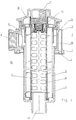
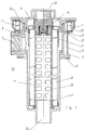
- the housing of the filter consists of a filter bowl 1 and a filter head 2 connected tightly to it.
- the filter bowl 1 With the filter bowl 1, the filter is inserted into an opening in a top wall of a closed container (not shown in the drawing) with an interior 3.
- an annular seal 4 on the underside of the filter head 2 represents a seal against the container wall.
- In the filter housing 1, 2 is a filter element 5, 6 surrounding and continuing in the filter head 2 above the latter Inlet space 8 is formed.
- An inlet 9 provided on the filter head 2 for hydraulic fluid to be filtered opens into the inlet space 8.
- the interior of the support element 6 of the annular filter element 5 forms an outlet space 11, which opens into an outlet 12 which leads into the interior 3 of the container (not shown) to be ventilated.
- a bypass valve 10 is arranged in the upper end region of the support element 6, through which in its open state hydraulic fluid can flow directly from the inlet space 8 into the outlet space 11, bypassing the filter element 5, 6.
- breakable connections 14 prepared in a ring flank 13 are still closed.
- a cover plate 15 is screwed onto the filter head 2 and closes off the filter head 2.
- connections 14 are broken in the ring flank 13. These open connections 14 are connected via a ventilation space 16 in the filter head 2 to the interior 3 of the container, not shown.
- a ventilation ring filter element 17 is attached tightly between the ring flank 13 and a projecting annular edge area 19 of a cover 20 screwed onto the filter head 2.
- the bearing surface on the ring flank 13 for the ventilation ring filter element 17 is enlarged radially on the outside by an annular body 18 placed flush against the ring flank 13.
- This annular body 18 has an L-shape in cross section, so that separated liquid penetrating the ventilation ring filter element 17 perpendicularly below can be collected radially on the outside and returned through the ventilation ring filter element into the interior 3 of the container.
- lids 15, 20 are used for the applications with and without ventilation ring filter 20 in the exemplary embodiments shown, this is of course not necessary. If a cover with a projecting edge area 19 is used, such a cover can rather be used for both applications.
- the covers 15 and 20 can each have an opening in the form of a connecting piece 21 connecting the interior of the filter to the outside on its axial end face.
- the connector 21 can replace the inlet 9.
Landscapes
- Chemical & Material Sciences (AREA)
- Chemical Kinetics & Catalysis (AREA)
- Filtering Of Dispersed Particles In Gases (AREA)
- Infusion, Injection, And Reservoir Apparatuses (AREA)
- Thermally Insulated Containers For Foods (AREA)
- Devices For Use In Laboratory Experiments (AREA)
- Ink Jet (AREA)
Applications Claiming Priority (4)
| Application Number | Priority Date | Filing Date | Title |
|---|---|---|---|
| DE19541962A DE19541962A1 (de) | 1995-11-10 | 1995-11-10 | Hydraulikfilter |
| DE19541962 | 1995-11-10 | ||
| DE19637004 | 1996-09-12 | ||
| DE19637004A DE19637004A1 (de) | 1996-09-12 | 1996-09-12 | Filter für in einen geschlossenen Behälter zurückfließende Flüssigkeit |
Publications (2)
| Publication Number | Publication Date |
|---|---|
| EP0773053A1 true EP0773053A1 (fr) | 1997-05-14 |
| EP0773053B1 EP0773053B1 (fr) | 2003-02-05 |
Family
ID=26020261
Family Applications (1)
| Application Number | Title | Priority Date | Filing Date |
|---|---|---|---|
| EP96117662A Expired - Lifetime EP0773053B1 (fr) | 1995-11-10 | 1996-11-05 | Filtre pour liquide s'écoulant dans un réservoir fermé |
Country Status (3)
| Country | Link |
|---|---|
| EP (1) | EP0773053B1 (fr) |
| AT (1) | ATE232129T1 (fr) |
| DE (1) | DE59610112D1 (fr) |
Cited By (6)
| Publication number | Priority date | Publication date | Assignee | Title |
|---|---|---|---|---|
| WO2003080216A1 (fr) * | 2002-03-18 | 2003-10-02 | Parker-Hannifin Corporation | Filtre dans le reservoir pour applications hydrauliques mobiles, et ensemble correspondant |
| DE10041884B4 (de) * | 2000-02-12 | 2005-08-25 | Hydac Filtertechnik Gmbh | Filtervorrichtung |
| DE10066173B4 (de) * | 2000-02-12 | 2007-04-19 | Hydac Filtertechnik Gmbh | Filtervorrichtung |
| WO2010118803A1 (fr) * | 2009-04-15 | 2010-10-21 | Hydac Filtertechnik Gmbh | Dispositif de filtration |
| WO2014032902A1 (fr) * | 2012-08-30 | 2014-03-06 | Mann+Hummel Gmbh | Elément filtrant et dispositif filtrant |
| WO2016116838A1 (fr) * | 2015-01-19 | 2016-07-28 | Interpump Hydraulics S.P.A. | Filtre à air et à huile dans un orifice d'admission d'huile d'un réservoir d'huile |
Families Citing this family (1)
| Publication number | Priority date | Publication date | Assignee | Title |
|---|---|---|---|---|
| EP3990155A1 (fr) * | 2019-06-25 | 2022-05-04 | Donaldson Company, Inc. | Capuchon d'extrémité d'élément filtre doté d'un carénage |
Citations (3)
| Publication number | Priority date | Publication date | Assignee | Title |
|---|---|---|---|---|
| DE2235246A1 (de) | 1972-07-18 | 1974-02-14 | Argo Feinmechanik | Filter, insbesondere ruecklauffilter |
| EP0512639A1 (fr) * | 1991-05-06 | 1992-11-11 | Fairey Arlon B.V. | Retour-filtre pour reservoir |
| DE4310234C1 (de) * | 1993-03-30 | 1994-08-18 | Argo Feinmechanik | Rücklauffilter für Flüssigkeiten |
-
1996
- 1996-11-05 AT AT96117662T patent/ATE232129T1/de active
- 1996-11-05 EP EP96117662A patent/EP0773053B1/fr not_active Expired - Lifetime
- 1996-11-05 DE DE59610112T patent/DE59610112D1/de not_active Expired - Fee Related
Patent Citations (3)
| Publication number | Priority date | Publication date | Assignee | Title |
|---|---|---|---|---|
| DE2235246A1 (de) | 1972-07-18 | 1974-02-14 | Argo Feinmechanik | Filter, insbesondere ruecklauffilter |
| EP0512639A1 (fr) * | 1991-05-06 | 1992-11-11 | Fairey Arlon B.V. | Retour-filtre pour reservoir |
| DE4310234C1 (de) * | 1993-03-30 | 1994-08-18 | Argo Feinmechanik | Rücklauffilter für Flüssigkeiten |
Cited By (8)
| Publication number | Priority date | Publication date | Assignee | Title |
|---|---|---|---|---|
| DE10041884B4 (de) * | 2000-02-12 | 2005-08-25 | Hydac Filtertechnik Gmbh | Filtervorrichtung |
| DE10066173B4 (de) * | 2000-02-12 | 2007-04-19 | Hydac Filtertechnik Gmbh | Filtervorrichtung |
| WO2003080216A1 (fr) * | 2002-03-18 | 2003-10-02 | Parker-Hannifin Corporation | Filtre dans le reservoir pour applications hydrauliques mobiles, et ensemble correspondant |
| US6887376B2 (en) | 2002-03-18 | 2005-05-03 | Parker-Hannifin Corporation | Mobile in-tank filter and assembly therefor |
| CN1295011C (zh) * | 2002-03-18 | 2007-01-17 | 帕克-汉尼芬公司 | 移动罐内过滤器及其组件 |
| WO2010118803A1 (fr) * | 2009-04-15 | 2010-10-21 | Hydac Filtertechnik Gmbh | Dispositif de filtration |
| WO2014032902A1 (fr) * | 2012-08-30 | 2014-03-06 | Mann+Hummel Gmbh | Elément filtrant et dispositif filtrant |
| WO2016116838A1 (fr) * | 2015-01-19 | 2016-07-28 | Interpump Hydraulics S.P.A. | Filtre à air et à huile dans un orifice d'admission d'huile d'un réservoir d'huile |
Also Published As
| Publication number | Publication date |
|---|---|
| ATE232129T1 (de) | 2003-02-15 |
| EP0773053B1 (fr) | 2003-02-05 |
| DE59610112D1 (de) | 2003-03-13 |
Similar Documents
| Publication | Publication Date | Title |
|---|---|---|
| DE3586681T2 (de) | Filter mit verschlusskappe die stroemungsumkehrung zulaesst. | |
| EP2102484B1 (fr) | Filtre à carburant d'un moteur à combustion de véhicule | |
| DE602004006277T2 (de) | Filteranordnung mit entlüftetem filterelement | |
| EP0314915B1 (fr) | Filtre permettant la purification des huiles de graissage | |
| EP2649292B1 (fr) | Filtre à carburant | |
| DE19716085B4 (de) | Filter, insbesondere für Kraftstoffe von Verbrennungsmotoren | |
| DE3882270T2 (de) | Abflussventil für Fluidum-Filter. | |
| DE69030270T2 (de) | Brennstoff-filter | |
| DE3409219C2 (fr) | ||
| DE19538883A1 (de) | Filter für Flüssigkeiten, insbesondere Dieselkraftstoff | |
| EP2542324A1 (fr) | Dispositif de filtration ainsi qu'élément filtrant prévu pour ce dernier | |
| DE112007001880T5 (de) | Schnellablaßfilter | |
| DE112010003242T5 (de) | "Kein Filter kein Betrieb"-Flüssigkeitsfiltersystem | |
| DE112007001879T5 (de) | Schnellablaßfilter | |
| EP1389273A1 (fr) | Procede permettant d'evacuer de l'eau separee dans un filtre a combustible et dispositif correspondant | |
| EP0848978B1 (fr) | Tube support destiné à recevoir un élément filtrant annulaire | |
| DE10111064A1 (de) | Filtermodul, Einbausatz für ein Filtermodul und Filtervorrichtung | |
| EP1648583B1 (fr) | Ensemble filtre a huile et element filtrant | |
| DE102008027374A1 (de) | Filter für Betriebsmittel einer Brennkraftmaschine, und Bestandteile eines solchen Filters | |
| DE4330839A1 (de) | Filter für die Reinigung von Flüssigkeiten | |
| EP3341105B1 (fr) | Filtre à fluide et cartouche filtrante pour ledit filtre | |
| EP0773053B1 (fr) | Filtre pour liquide s'écoulant dans un réservoir fermé | |
| DE102006060129A1 (de) | Ringfiltereinsatz für ein Flüssigkeitsfilter | |
| EP0088148A2 (fr) | Filtre | |
| EP1090666A1 (fr) | Filtre à liquide connecté aux tuyaux souples |
Legal Events
| Date | Code | Title | Description |
|---|---|---|---|
| PUAI | Public reference made under article 153(3) epc to a published international application that has entered the european phase |
Free format text: ORIGINAL CODE: 0009012 |
|
| AK | Designated contracting states |
Kind code of ref document: A1 Designated state(s): AT DE FR IT SE |
|
| 17P | Request for examination filed |
Effective date: 19970614 |
|
| RAP1 | Party data changed (applicant data changed or rights of an application transferred) |
Owner name: MAHLE FILTERSYSTEME GMBH |
|
| 17Q | First examination report despatched |
Effective date: 20000901 |
|
| GRAH | Despatch of communication of intention to grant a patent |
Free format text: ORIGINAL CODE: EPIDOS IGRA |
|
| RTI1 | Title (correction) |
Free format text: FILTER FOR LIQUID FLOWING INTO A CLOSED RESERVOIR |
|
| GRAH | Despatch of communication of intention to grant a patent |
Free format text: ORIGINAL CODE: EPIDOS IGRA |
|
| GRAA | (expected) grant |
Free format text: ORIGINAL CODE: 0009210 |
|
| AK | Designated contracting states |
Designated state(s): AT DE FR IT SE |
|
| PG25 | Lapsed in a contracting state [announced via postgrant information from national office to epo] |
Ref country code: IT Free format text: LAPSE BECAUSE OF FAILURE TO SUBMIT A TRANSLATION OF THE DESCRIPTION OR TO PAY THE FEE WITHIN THE PRE;WARNING: LAPSES OF ITALIAN PATENTS WITH EFFECTIVE DATE BEFORE 2007 MAY HAVE OCCURRED AT ANY TIME BEFORE 2007. THE CORRECT EFFECTIVE DATE MAY BE DIFFERENT FROM THE ONE RECORDED.SCRIBED TIME-LIMIT Effective date: 20030205 |
|
| REF | Corresponds to: |
Ref document number: 59610112 Country of ref document: DE Date of ref document: 20030313 Kind code of ref document: P |
|
| PG25 | Lapsed in a contracting state [announced via postgrant information from national office to epo] |
Ref country code: SE Free format text: LAPSE BECAUSE OF FAILURE TO SUBMIT A TRANSLATION OF THE DESCRIPTION OR TO PAY THE FEE WITHIN THE PRESCRIBED TIME-LIMIT Effective date: 20030505 |
|
| ET | Fr: translation filed | ||
| PLBE | No opposition filed within time limit |
Free format text: ORIGINAL CODE: 0009261 |
|
| STAA | Information on the status of an ep patent application or granted ep patent |
Free format text: STATUS: NO OPPOSITION FILED WITHIN TIME LIMIT |
|
| 26N | No opposition filed |
Effective date: 20031106 |
|
| PGFP | Annual fee paid to national office [announced via postgrant information from national office to epo] |
Ref country code: DE Payment date: 20071122 Year of fee payment: 12 |
|
| PG25 | Lapsed in a contracting state [announced via postgrant information from national office to epo] |
Ref country code: DE Free format text: LAPSE BECAUSE OF NON-PAYMENT OF DUE FEES Effective date: 20090603 |
|
| PGFP | Annual fee paid to national office [announced via postgrant information from national office to epo] |
Ref country code: FR Payment date: 20101209 Year of fee payment: 15 Ref country code: AT Payment date: 20101122 Year of fee payment: 15 |
|
| REG | Reference to a national code |
Ref country code: FR Ref legal event code: ST Effective date: 20120731 |
|
| REG | Reference to a national code |
Ref country code: AT Ref legal event code: MM01 Ref document number: 232129 Country of ref document: AT Kind code of ref document: T Effective date: 20111105 |
|
| PG25 | Lapsed in a contracting state [announced via postgrant information from national office to epo] |
Ref country code: FR Free format text: LAPSE BECAUSE OF NON-PAYMENT OF DUE FEES Effective date: 20111130 |
|
| PG25 | Lapsed in a contracting state [announced via postgrant information from national office to epo] |
Ref country code: AT Free format text: LAPSE BECAUSE OF NON-PAYMENT OF DUE FEES Effective date: 20111105 |