EP0773072A1 - Dispositif pour serrer une bague de laminage - Google Patents
Dispositif pour serrer une bague de laminage Download PDFInfo
- Publication number
- EP0773072A1 EP0773072A1 EP96116657A EP96116657A EP0773072A1 EP 0773072 A1 EP0773072 A1 EP 0773072A1 EP 96116657 A EP96116657 A EP 96116657A EP 96116657 A EP96116657 A EP 96116657A EP 0773072 A1 EP0773072 A1 EP 0773072A1
- Authority
- EP
- European Patent Office
- Prior art keywords
- ring
- cap
- spacer
- assembly
- rolling
- Prior art date
- Legal status (The legal status is an assumption and is not a legal conclusion. Google has not performed a legal analysis and makes no representation as to the accuracy of the status listed.)
- Granted
Links
Images

Classifications
-
- B—PERFORMING OPERATIONS; TRANSPORTING
- B21—MECHANICAL METAL-WORKING WITHOUT ESSENTIALLY REMOVING MATERIAL; PUNCHING METAL
- B21B—ROLLING OF METAL
- B21B27/00—Rolls, roll alloys or roll fabrication; Lubricating, cooling or heating rolls while in use
- B21B27/02—Shape or construction of rolls
- B21B27/03—Sleeved rolls
- B21B27/035—Rolls for bars, rods, rounds, tubes, wire or the like
-
- Y—GENERAL TAGGING OF NEW TECHNOLOGICAL DEVELOPMENTS; GENERAL TAGGING OF CROSS-SECTIONAL TECHNOLOGIES SPANNING OVER SEVERAL SECTIONS OF THE IPC; TECHNICAL SUBJECTS COVERED BY FORMER USPC CROSS-REFERENCE ART COLLECTIONS [XRACs] AND DIGESTS
- Y10—TECHNICAL SUBJECTS COVERED BY FORMER USPC
- Y10T—TECHNICAL SUBJECTS COVERED BY FORMER US CLASSIFICATION
- Y10T29/00—Metal working
- Y10T29/53—Means to assemble or disassemble
- Y10T29/53796—Puller or pusher means, contained force multiplying operator
- Y10T29/53848—Puller or pusher means, contained force multiplying operator having screw operator
-
- Y—GENERAL TAGGING OF NEW TECHNOLOGICAL DEVELOPMENTS; GENERAL TAGGING OF CROSS-SECTIONAL TECHNOLOGIES SPANNING OVER SEVERAL SECTIONS OF THE IPC; TECHNICAL SUBJECTS COVERED BY FORMER USPC CROSS-REFERENCE ART COLLECTIONS [XRACs] AND DIGESTS
- Y10—TECHNICAL SUBJECTS COVERED BY FORMER USPC
- Y10T—TECHNICAL SUBJECTS COVERED BY FORMER US CLASSIFICATION
- Y10T403/00—Joints and connections
- Y10T403/70—Interfitted members
- Y10T403/7018—Interfitted members including separably interposed key
Definitions
- This invention concerns an assembly to clamp a rolling ring as set forth in the main claim.
- the assembly to clamp a rolling ring according to the invention is applied to the field of rolling and, to be more exact, to the clamping of the rolling rings on ring-bearing shafts of a rolling mill stand.
- the rolling ring In rolling mill stands of the state of the art of a type including ring-bearing shafts cooperating with a rolling ring, the rolling ring is normally fitted to the respective shaft by positioning in series a labyrinth-type ring containing an inner channel, the rolling ring, a cap rotatably clamped to the rolling ring and a closure flange which is associated with the shaft by means of a locking screw.
- the rotational clamping of the cap to the rolling ring is normally ensured by frontal coupling elements of a male and female type which are included respectively on the opposed surfaces of the cap and of the rolling ring.
- a spacer is inserted between the rolling ring and the cap so as to ensure the presence of a gap therebetween of a desired value and thus to prevent direct contact between the cap and the rolling ring.
- This spacer is fitted to an alignment bush which cooperates with the rolling ring and with the cap.
- the spacer is stressed in an anomalous manner with a resulting stripping of the screw thread and with a consequent inability to re-use the system.
- the purpose of this invention is to provide an assembly for the clamping of the rolling ring to the ring-bearing shaft whereby the clamping assembly eliminates the problems linked to incorrect installation and to processing faults.
- the clamping assembly according to the invention always ensures the presence of a required longitudinal gap between the rolling ring and the cap and, if this gap does not exist, does not cause damage which would render the whole system unsuitable for further use.
- the clamping assembly according to the invention provides for the use of a spacer having a cylindrical alignment surface which cooperates with the cap and which enables the spacer to be displaced axially by a determined and required travel, which is advantageously of a value of some millimetres.
- the protruding part of the keys cooperates with mating seatings machined in a coordinated position on the outer surface of the spacer.
- the clamping assembly includes wear-resistant bearing rings between the labyrinth ring cooperating with the rolling ring and the ring-bearing shaft so as to prevent any sliding being able to damage the ring-bearing shaft, above all during the beginning of the rolling of a new bar.
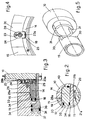
- the reference number 10 in the figures denotes a rolling ring associated with a ring-bearing shaft 11 of a rolling mill stand, which is not shown here.
- the rolling ring 10 cooperates with a clamping assembly 12, which ensures longitudinal and rotational clamping of the rolling ring 10 to the ring-bearing shaft 11 and which ensures at the same time a ready installation/dismantling of the rolling ring 10.
- the clamping assembly 12 comprises a labyrinth-type ring 13 containing an inner channel, a spacer 14, a cap 15, a closure flange 16, a locking screw 17 and a tapered alignment bush 18 cooperating both with the rolling ring 10 and with the spacer 14 and cap 15.
- the labyrinth ring 13 cooperates with a wear-prevention spacer 27, which abuts against a ledge 28 of the ring-bearing shaft 11 and includes between the labyrinth ring 13 and the ring-bearing shaft 11 a bearing 22 having the function of a wear-prevention ring.
- the spacer 27 and the bearing 22 may be associated with each other also to form one single body.
- the rotational clamping of the cap 15 to the rolling ring 10 is ensured by frontal male coupling elements 30, which are included on the surface of the cap 15 and which cooperate with mating female elements 31 included in the opposed surface of the rolling ring 10.
- each of the frontal male 30 and mating female 31 coupling elements comprises two diametrically opposed elements, as shown diagrammatically in Fig.5.
- the cap 15 has a cylindrical alignment surface 19 including a frontal abutment surface 33 which abuts against the spacer 14.
- the spacer 14 includes packings 34 cooperating with a first chamber 35 machined in the cap 15 in cooperation with the alignment bush 18.
- Pins 38 cooperate with the head 36 and clamp the alignment bush 18 mechanically in the clamping position.
- a first feeder conduit 39 cooperates with the first chamber 35, while a second feeder conduit 32 cooperates with the second chamber 37.
- the spacer 14 includes abutment means 40 that cooperate with the rolling ring 10.
- the clamping assembly 12 comprises also rotation-prevention means 20 between the tapered alignment bush 18 and the cap 15.
- the rotation-prevention means 20 include a tooth 21a associated with the inner surface of the tapered alignment bush 18, this tooth 21a being engaged with a mating tooth 21b located in a coordinated position on the cap 15.
- the spacer 14 in the clamping assembly 12 according to the invention is clamped to the cap 15 by keys 23 positioned in seatings 24 machined in the male frontal coupling elements 30 and including a protruding part 23a facing towards the axis of rotation of the ring-bearing shaft 11.
- This protruding part 23a cooperates with a seating 25 of a mating form machined in the spacer 14 so as to ensure reciprocal circumferential clamping that permits longitudinal sliding of the spacer 14.
- Each key 23 is associated with the cap 15 by means of a fixture screw 26, which, in the event of incorrect functioning or clamping, breaks and thus prevents more severe damage.
- the distance between the frontal abutment 33 and the abutment means 40 has the effect that a first longitudinal gap 29a of a required value is always present between the opposed surfaces of the rolling ring 10 and of the cap 15; a second gap 29b is also present between the frontal coupling elements 30, 31.
Landscapes
- Physics & Mathematics (AREA)
- Geometry (AREA)
- Engineering & Computer Science (AREA)
- Mechanical Engineering (AREA)
- Reduction Rolling/Reduction Stand/Operation Of Reduction Machine (AREA)
- Mounting Of Bearings Or Others (AREA)
- Rolling Contact Bearings (AREA)
- Support Of The Bearing (AREA)
- Buffer Packaging (AREA)
- Load-Engaging Elements For Cranes (AREA)
- Rolls And Other Rotary Bodies (AREA)
- Laying Of Electric Cables Or Lines Outside (AREA)
- Solid-Sorbent Or Filter-Aiding Compositions (AREA)
- Supplying Of Containers To The Packaging Station (AREA)
Applications Claiming Priority (2)
| Application Number | Priority Date | Filing Date | Title |
|---|---|---|---|
| IT95UD000223A IT1281447B1 (it) | 1995-11-09 | 1995-11-09 | Gruppo di bloccaggio anello di laminazione |
| ITUD950223 | 1995-11-09 |
Publications (2)
| Publication Number | Publication Date |
|---|---|
| EP0773072A1 true EP0773072A1 (fr) | 1997-05-14 |
| EP0773072B1 EP0773072B1 (fr) | 2000-04-26 |
Family
ID=11421958
Family Applications (1)
| Application Number | Title | Priority Date | Filing Date |
|---|---|---|---|
| EP96116657A Expired - Lifetime EP0773072B1 (fr) | 1995-11-09 | 1996-10-17 | Dispositif pour serrer une bague de laminage |
Country Status (8)
| Country | Link |
|---|---|
| US (1) | US5782125A (fr) |
| EP (1) | EP0773072B1 (fr) |
| CN (1) | CN1152481A (fr) |
| AT (1) | ATE192052T1 (fr) |
| DE (1) | DE69607920T2 (fr) |
| ES (1) | ES2144682T3 (fr) |
| IT (1) | IT1281447B1 (fr) |
| TW (1) | TW316241B (fr) |
Cited By (2)
| Publication number | Priority date | Publication date | Assignee | Title |
|---|---|---|---|---|
| EP1106272A1 (fr) * | 1999-12-07 | 2001-06-13 | SMS Demag AG | Rouleau, en particulier d'une installation de sondage de tuyaux |
| US10694264B2 (en) | 2013-09-20 | 2020-06-23 | Koninklijke Kpn N.V. | Correlating timeline information between media streams |
Families Citing this family (6)
| Publication number | Priority date | Publication date | Assignee | Title |
|---|---|---|---|---|
| DE10317312A1 (de) * | 2003-04-14 | 2004-11-25 | Langenstein & Schemann Gmbh | Vorrichtung zum Halten wenigstens einer Walze einer Walzmaschine |
| JP5109477B2 (ja) * | 2007-05-21 | 2012-12-26 | 三菱マテリアル株式会社 | 圧延ロール及び圧延機 |
| US8852065B2 (en) * | 2008-05-07 | 2014-10-07 | Mitsubishi Materials Corporation | Rolling roll, rolling ring, rolling mill, and rolling roll assembling method |
| NO330024B1 (no) * | 2009-11-26 | 2011-02-07 | Bolt Norge As | Anordning ved aksel-boringforbindelse |
| US9334890B2 (en) | 2012-01-24 | 2016-05-10 | Kennametal India Limited | Hardmetal roll clamping system onto the shaft and the method thereof |
| WO2015002737A1 (fr) * | 2013-07-01 | 2015-01-08 | Thomson Industries, Inc. | Appareil de manchon conique fendu |
Citations (8)
| Publication number | Priority date | Publication date | Assignee | Title |
|---|---|---|---|---|
| US3514136A (en) * | 1968-10-18 | 1970-05-26 | Kennametal Inc | Roll for rod mill and mounting arrangement therefor |
| EP0099073A1 (fr) * | 1982-07-16 | 1984-01-25 | Sms Schloemann-Siemag Aktiengesellschaft | Dispositif de serrage de disque ou d'anneaux de laminage de préférence dans un arrangement en porte-à-faux |
| US4581911A (en) * | 1983-03-07 | 1986-04-15 | Kabushiki Kaisha Kobe Seiko Sho | Cantilever type rolling mill |
| EP0214521A2 (fr) * | 1985-09-06 | 1987-03-18 | Sms Schloemann-Siemag Aktiengesellschaft | Laminoir à cylindres montés sur des arbres supportés dans les châssis de laminoir et entraînés d'un seul côté |
| EP0321139A1 (fr) * | 1987-12-16 | 1989-06-21 | MORGAN CONSTRUCTION COMPANY (a Massachusetts corporation) | Ensemble de cylindre en porte-à-faux |
| EP0342179A2 (fr) * | 1988-05-13 | 1989-11-15 | VOEST-ALPINE INDUSTRIEANLAGENBAU GESELLSCHAFT m.b.H. | Dispositif pour monter une bague de laminage sur un arbre de laminage |
| DE3834606A1 (de) * | 1988-10-11 | 1990-04-12 | Voest Alpine Ind Anlagen | Vorrichtung zum befestigen eines walzringes |
| EP0455082A1 (fr) * | 1990-05-04 | 1991-11-06 | Sms Schloemann-Siemag Aktiengesellschaft | Ligne combinée pour petits fers et fil |
Family Cites Families (4)
| Publication number | Priority date | Publication date | Assignee | Title |
|---|---|---|---|---|
| US3727957A (en) * | 1971-08-23 | 1973-04-17 | Kennametal Inc | Forming roll |
| DE3316289A1 (de) * | 1983-05-04 | 1984-11-08 | Uwe 2104 Hamburg Kark | Verbundwalze mit einem mittels einer konushuelse auf dem walzenkern gehaltenen walzenring |
| FR2547216A1 (fr) * | 1983-06-10 | 1984-12-14 | Sacilor | Dispositif perfectionne de manoeuvre et de reglage axial de cylindres horizontaux de cage de laminoir a profiles |
| US4776078A (en) * | 1987-07-06 | 1988-10-11 | Howard Robert S | Sleeve mounting and removal tool |
-
1995
- 1995-11-09 IT IT95UD000223A patent/IT1281447B1/it active IP Right Grant
-
1996
- 1996-10-17 AT AT96116657T patent/ATE192052T1/de not_active IP Right Cessation
- 1996-10-17 ES ES96116657T patent/ES2144682T3/es not_active Expired - Lifetime
- 1996-10-17 DE DE69607920T patent/DE69607920T2/de not_active Expired - Fee Related
- 1996-10-17 EP EP96116657A patent/EP0773072B1/fr not_active Expired - Lifetime
- 1996-10-23 TW TW085112990A patent/TW316241B/zh active
- 1996-10-31 US US08/740,605 patent/US5782125A/en not_active Expired - Fee Related
- 1996-11-08 CN CN96114529.3A patent/CN1152481A/zh active Pending
Patent Citations (8)
| Publication number | Priority date | Publication date | Assignee | Title |
|---|---|---|---|---|
| US3514136A (en) * | 1968-10-18 | 1970-05-26 | Kennametal Inc | Roll for rod mill and mounting arrangement therefor |
| EP0099073A1 (fr) * | 1982-07-16 | 1984-01-25 | Sms Schloemann-Siemag Aktiengesellschaft | Dispositif de serrage de disque ou d'anneaux de laminage de préférence dans un arrangement en porte-à-faux |
| US4581911A (en) * | 1983-03-07 | 1986-04-15 | Kabushiki Kaisha Kobe Seiko Sho | Cantilever type rolling mill |
| EP0214521A2 (fr) * | 1985-09-06 | 1987-03-18 | Sms Schloemann-Siemag Aktiengesellschaft | Laminoir à cylindres montés sur des arbres supportés dans les châssis de laminoir et entraînés d'un seul côté |
| EP0321139A1 (fr) * | 1987-12-16 | 1989-06-21 | MORGAN CONSTRUCTION COMPANY (a Massachusetts corporation) | Ensemble de cylindre en porte-à-faux |
| EP0342179A2 (fr) * | 1988-05-13 | 1989-11-15 | VOEST-ALPINE INDUSTRIEANLAGENBAU GESELLSCHAFT m.b.H. | Dispositif pour monter une bague de laminage sur un arbre de laminage |
| DE3834606A1 (de) * | 1988-10-11 | 1990-04-12 | Voest Alpine Ind Anlagen | Vorrichtung zum befestigen eines walzringes |
| EP0455082A1 (fr) * | 1990-05-04 | 1991-11-06 | Sms Schloemann-Siemag Aktiengesellschaft | Ligne combinée pour petits fers et fil |
Non-Patent Citations (1)
| Title |
|---|
| D. BUDDE ET AL.: "Neue Entwicklungen der Drahtwalztechnik für hochlegierte Werkstoffe", STAHL UND EISEN, vol. 112, no. 11, 9 November 1992 (1992-11-09), DÜSSELDORF DE, pages 83 - 89, XP000339458 * |
Cited By (2)
| Publication number | Priority date | Publication date | Assignee | Title |
|---|---|---|---|---|
| EP1106272A1 (fr) * | 1999-12-07 | 2001-06-13 | SMS Demag AG | Rouleau, en particulier d'une installation de sondage de tuyaux |
| US10694264B2 (en) | 2013-09-20 | 2020-06-23 | Koninklijke Kpn N.V. | Correlating timeline information between media streams |
Also Published As
| Publication number | Publication date |
|---|---|
| US5782125A (en) | 1998-07-21 |
| ITUD950223A1 (it) | 1997-05-09 |
| ITUD950223A0 (fr) | 1995-11-09 |
| TW316241B (fr) | 1997-09-21 |
| ES2144682T3 (es) | 2000-06-16 |
| AU705874B2 (en) | 1999-06-03 |
| DE69607920T2 (de) | 2000-08-17 |
| CN1152481A (zh) | 1997-06-25 |
| IT1281447B1 (it) | 1998-02-18 |
| EP0773072B1 (fr) | 2000-04-26 |
| DE69607920D1 (de) | 2000-05-31 |
| AU7031496A (en) | 1997-05-15 |
| ATE192052T1 (de) | 2000-05-15 |
Similar Documents
| Publication | Publication Date | Title |
|---|---|---|
| EP0799389B1 (fr) | Ensemble palier a dispositif de fixation ameliore | |
| US5323600A (en) | Liner stop assembly for a combustor | |
| EP0773072B1 (fr) | Dispositif pour serrer une bague de laminage | |
| DE68903331T2 (de) | Drehende dichtung mit integriertem magnetischen kodierer, insbesondere fuer waelzlager mit messwertgeber. | |
| US4398775A (en) | Journal bearing with one axially divided inner or outer ring | |
| DE112019003837T5 (de) | Dicht-element und lager-vorrichtung für ein rad mit dicht-element | |
| DE69815760T2 (de) | Kugellager mit Drehzahlsensor | |
| DE3444587A1 (de) | Vorrichtung zur befestigung von laufschaufeln | |
| US4733458A (en) | Bayonet coupling for axially mounting a ring-shaped member on a shaft stub | |
| US4233855A (en) | Mechanism for the axial shifting of an anti-friction bearing | |
| DE9017861U1 (de) | Zweireihiges Schrägwälzlager | |
| US5836191A (en) | Continuous extrusion apparatus | |
| US3733108A (en) | Thrust mechanism for a mill roll bearing assembly and the like | |
| DE8912970U1 (de) | Käfigring zur Führung der Wälzkörper im Wälzlager | |
| DE3514142C2 (fr) | ||
| DE20212847U1 (de) | Geteilte Mitnehmeranordnung für eine Gleitringdichtung | |
| DE19608975C2 (de) | Transport- und Montagevorrichtung für einen Gehäuseverschlußdeckel | |
| DE2703514A1 (de) | Lagerung fuer den schaft eines offenend-spinnrotors | |
| DE2515200A1 (de) | Abdichtungen | |
| EP1094907B1 (fr) | Moule a pas de pelerin a changement rapide et ensemble con u a cet effet et muni d'un arbre porte-bobines | |
| DE19831302A1 (de) | Axiale Festlegung einer Wälzlagerung | |
| EP3534025A1 (fr) | Palier | |
| DE69308503T2 (de) | Dichtungsvorrichtung für Maschinenlager | |
| DE19532549A1 (de) | Wellenabdichtung | |
| US5344263A (en) | High-precision interchangeable tool holder |
Legal Events
| Date | Code | Title | Description |
|---|---|---|---|
| PUAI | Public reference made under article 153(3) epc to a published international application that has entered the european phase |
Free format text: ORIGINAL CODE: 0009012 |
|
| AK | Designated contracting states |
Kind code of ref document: A1 Designated state(s): AT BE DE ES FR GB IT SE |
|
| 17P | Request for examination filed |
Effective date: 19971031 |
|
| GRAG | Despatch of communication of intention to grant |
Free format text: ORIGINAL CODE: EPIDOS AGRA |
|
| 17Q | First examination report despatched |
Effective date: 19990727 |
|
| GRAG | Despatch of communication of intention to grant |
Free format text: ORIGINAL CODE: EPIDOS AGRA |
|
| GRAH | Despatch of communication of intention to grant a patent |
Free format text: ORIGINAL CODE: EPIDOS IGRA |
|
| GRAH | Despatch of communication of intention to grant a patent |
Free format text: ORIGINAL CODE: EPIDOS IGRA |
|
| GRAA | (expected) grant |
Free format text: ORIGINAL CODE: 0009210 |
|
| ITF | It: translation for a ep patent filed | ||
| AK | Designated contracting states |
Kind code of ref document: B1 Designated state(s): AT BE DE ES FR GB IT SE |
|
| REF | Corresponds to: |
Ref document number: 192052 Country of ref document: AT Date of ref document: 20000515 Kind code of ref document: T |
|
| ET | Fr: translation filed | ||
| REF | Corresponds to: |
Ref document number: 69607920 Country of ref document: DE Date of ref document: 20000531 |
|
| REG | Reference to a national code |
Ref country code: ES Ref legal event code: FG2A Ref document number: 2144682 Country of ref document: ES Kind code of ref document: T3 |
|
| PLBE | No opposition filed within time limit |
Free format text: ORIGINAL CODE: 0009261 |
|
| STAA | Information on the status of an ep patent application or granted ep patent |
Free format text: STATUS: NO OPPOSITION FILED WITHIN TIME LIMIT |
|
| 26N | No opposition filed | ||
| REG | Reference to a national code |
Ref country code: GB Ref legal event code: IF02 |
|
| PGFP | Annual fee paid to national office [announced via postgrant information from national office to epo] |
Ref country code: GB Payment date: 20080926 Year of fee payment: 13 |
|
| PGFP | Annual fee paid to national office [announced via postgrant information from national office to epo] |
Ref country code: DE Payment date: 20081030 Year of fee payment: 13 |
|
| PGFP | Annual fee paid to national office [announced via postgrant information from national office to epo] |
Ref country code: SE Payment date: 20080926 Year of fee payment: 13 Ref country code: ES Payment date: 20081007 Year of fee payment: 13 Ref country code: BE Payment date: 20080926 Year of fee payment: 13 Ref country code: AT Payment date: 20080924 Year of fee payment: 13 |
|
| PGFP | Annual fee paid to national office [announced via postgrant information from national office to epo] |
Ref country code: IT Payment date: 20081016 Year of fee payment: 13 |
|
| PGFP | Annual fee paid to national office [announced via postgrant information from national office to epo] |
Ref country code: FR Payment date: 20081028 Year of fee payment: 13 |
|
| BERE | Be: lapsed |
Owner name: *DANIELI & C. OFFICINE MECCANICHE S.P.A. Effective date: 20091031 |
|
| EUG | Se: european patent has lapsed | ||
| REG | Reference to a national code |
Ref country code: FR Ref legal event code: ST Effective date: 20100630 |
|
| PG25 | Lapsed in a contracting state [announced via postgrant information from national office to epo] |
Ref country code: FR Free format text: LAPSE BECAUSE OF NON-PAYMENT OF DUE FEES Effective date: 20091102 Ref country code: DE Free format text: LAPSE BECAUSE OF NON-PAYMENT OF DUE FEES Effective date: 20100501 |
|
| PG25 | Lapsed in a contracting state [announced via postgrant information from national office to epo] |
Ref country code: AT Free format text: LAPSE BECAUSE OF NON-PAYMENT OF DUE FEES Effective date: 20091017 |
|
| PG25 | Lapsed in a contracting state [announced via postgrant information from national office to epo] |
Ref country code: BE Free format text: LAPSE BECAUSE OF NON-PAYMENT OF DUE FEES Effective date: 20091031 |
|
| PG25 | Lapsed in a contracting state [announced via postgrant information from national office to epo] |
Ref country code: GB Free format text: LAPSE BECAUSE OF NON-PAYMENT OF DUE FEES Effective date: 20091017 |
|
| PG25 | Lapsed in a contracting state [announced via postgrant information from national office to epo] |
Ref country code: IT Free format text: LAPSE BECAUSE OF NON-PAYMENT OF DUE FEES Effective date: 20091017 |
|
| REG | Reference to a national code |
Ref country code: ES Ref legal event code: FD2A Effective date: 20110331 |
|
| PG25 | Lapsed in a contracting state [announced via postgrant information from national office to epo] |
Ref country code: SE Free format text: LAPSE BECAUSE OF NON-PAYMENT OF DUE FEES Effective date: 20091018 |
|
| PG25 | Lapsed in a contracting state [announced via postgrant information from national office to epo] |
Ref country code: ES Free format text: LAPSE BECAUSE OF NON-PAYMENT OF DUE FEES Effective date: 20110321 |
|
| PG25 | Lapsed in a contracting state [announced via postgrant information from national office to epo] |
Ref country code: ES Free format text: LAPSE BECAUSE OF NON-PAYMENT OF DUE FEES Effective date: 20091018 |