EP0773109B1 - Farbstoffnachfüllverfahren und -vorrichtung, Tintenbehälter und Tintenstrahlaufzeichnungsgerät mit einer solchen Vorrichtung - Google Patents
Farbstoffnachfüllverfahren und -vorrichtung, Tintenbehälter und Tintenstrahlaufzeichnungsgerät mit einer solchen Vorrichtung Download PDFInfo
- Publication number
- EP0773109B1 EP0773109B1 EP96117851A EP96117851A EP0773109B1 EP 0773109 B1 EP0773109 B1 EP 0773109B1 EP 96117851 A EP96117851 A EP 96117851A EP 96117851 A EP96117851 A EP 96117851A EP 0773109 B1 EP0773109 B1 EP 0773109B1
- Authority
- EP
- European Patent Office
- Prior art keywords
- ink
- container
- ink container
- refilling
- delivery
- Prior art date
- Legal status (The legal status is an assumption and is not a legal conclusion. Google has not performed a legal analysis and makes no representation as to the accuracy of the status listed.)
- Expired - Lifetime
Links
- 238000000034 method Methods 0.000 title description 17
- 239000000835 fiber Substances 0.000 claims description 24
- 239000000463 material Substances 0.000 claims description 15
- 230000005499 meniscus Effects 0.000 claims description 15
- 230000000717 retained effect Effects 0.000 claims description 5
- 238000007599 discharging Methods 0.000 claims 2
- 239000012530 fluid Substances 0.000 claims 1
- 230000005484 gravity Effects 0.000 claims 1
- 230000001939 inductive effect Effects 0.000 claims 1
- 239000000976 ink Substances 0.000 description 662
- 230000002745 absorbent Effects 0.000 description 18
- 239000002250 absorbent Substances 0.000 description 18
- 230000003068 static effect Effects 0.000 description 13
- 238000003780 insertion Methods 0.000 description 10
- 230000037431 insertion Effects 0.000 description 10
- 230000008569 process Effects 0.000 description 6
- 238000009434 installation Methods 0.000 description 5
- 238000003825 pressing Methods 0.000 description 5
- 238000009423 ventilation Methods 0.000 description 5
- 239000011148 porous material Substances 0.000 description 4
- 241000287828 Gallus gallus Species 0.000 description 3
- 238000005192 partition Methods 0.000 description 3
- 230000002093 peripheral effect Effects 0.000 description 3
- 239000004698 Polyethylene Substances 0.000 description 2
- 230000007423 decrease Effects 0.000 description 2
- 230000007246 mechanism Effects 0.000 description 2
- 239000012466 permeate Substances 0.000 description 2
- -1 polypropylene Polymers 0.000 description 2
- 238000009877 rendering Methods 0.000 description 2
- 229920000049 Carbon (fiber) Polymers 0.000 description 1
- 229920000914 Metallic fiber Polymers 0.000 description 1
- 239000004677 Nylon Substances 0.000 description 1
- 239000004743 Polypropylene Substances 0.000 description 1
- 239000004809 Teflon Substances 0.000 description 1
- 229920006362 Teflon® Polymers 0.000 description 1
- 239000011230 binding agent Substances 0.000 description 1
- 239000004917 carbon fiber Substances 0.000 description 1
- 229920002678 cellulose Polymers 0.000 description 1
- 239000001913 cellulose Substances 0.000 description 1
- 239000000919 ceramic Substances 0.000 description 1
- 229910010293 ceramic material Inorganic materials 0.000 description 1
- 230000008859 change Effects 0.000 description 1
- 238000011109 contamination Methods 0.000 description 1
- 238000007796 conventional method Methods 0.000 description 1
- 230000001419 dependent effect Effects 0.000 description 1
- 238000011161 development Methods 0.000 description 1
- 230000018109 developmental process Effects 0.000 description 1
- 230000008034 disappearance Effects 0.000 description 1
- 229920001971 elastomer Polymers 0.000 description 1
- 239000003365 glass fiber Substances 0.000 description 1
- 238000002347 injection Methods 0.000 description 1
- 239000007924 injection Substances 0.000 description 1
- 238000005304 joining Methods 0.000 description 1
- 238000012423 maintenance Methods 0.000 description 1
- 238000004519 manufacturing process Methods 0.000 description 1
- VNWKTOKETHGBQD-UHFFFAOYSA-N methane Chemical compound C VNWKTOKETHGBQD-UHFFFAOYSA-N 0.000 description 1
- 229920001778 nylon Polymers 0.000 description 1
- 229920000728 polyester Polymers 0.000 description 1
- 229920000573 polyethylene Polymers 0.000 description 1
- 229920001155 polypropylene Polymers 0.000 description 1
- 229920002635 polyurethane Polymers 0.000 description 1
- 239000004814 polyurethane Substances 0.000 description 1
- 239000000047 product Substances 0.000 description 1
- 230000009467 reduction Effects 0.000 description 1
- 230000001105 regulatory effect Effects 0.000 description 1
- 239000011347 resin Substances 0.000 description 1
- 229920005989 resin Polymers 0.000 description 1
- 238000005549 size reduction Methods 0.000 description 1
- 238000000638 solvent extraction Methods 0.000 description 1
- 238000003860 storage Methods 0.000 description 1
- 238000011144 upstream manufacturing Methods 0.000 description 1
Images


Classifications
-
- B—PERFORMING OPERATIONS; TRANSPORTING
- B41—PRINTING; LINING MACHINES; TYPEWRITERS; STAMPS
- B41J—TYPEWRITERS; SELECTIVE PRINTING MECHANISMS, i.e. MECHANISMS PRINTING OTHERWISE THAN FROM A FORME; CORRECTION OF TYPOGRAPHICAL ERRORS
- B41J2/00—Typewriters or selective printing mechanisms characterised by the printing or marking process for which they are designed
- B41J2/005—Typewriters or selective printing mechanisms characterised by the printing or marking process for which they are designed characterised by bringing liquid or particles selectively into contact with a printing material
- B41J2/01—Ink jet
- B41J2/17—Ink jet characterised by ink handling
- B41J2/175—Ink supply systems ; Circuit parts therefor
- B41J2/17503—Ink cartridges
- B41J2/17513—Inner structure
-
- B—PERFORMING OPERATIONS; TRANSPORTING
- B41—PRINTING; LINING MACHINES; TYPEWRITERS; STAMPS
- B41J—TYPEWRITERS; SELECTIVE PRINTING MECHANISMS, i.e. MECHANISMS PRINTING OTHERWISE THAN FROM A FORME; CORRECTION OF TYPOGRAPHICAL ERRORS
- B41J2/00—Typewriters or selective printing mechanisms characterised by the printing or marking process for which they are designed
- B41J2/005—Typewriters or selective printing mechanisms characterised by the printing or marking process for which they are designed characterised by bringing liquid or particles selectively into contact with a printing material
- B41J2/01—Ink jet
- B41J2/17—Ink jet characterised by ink handling
- B41J2/175—Ink supply systems ; Circuit parts therefor
- B41J2/17503—Ink cartridges
- B41J2/17506—Refilling of the cartridge
Definitions
- the present invention relates to an ink refilling system used to refill ink into an ink container which stores the ink to be delivered to a recording head.
- it relates to an ink refilling system capable of effectively and reliably refilling even an ink container which is integrally and removably mountable on a recording head comprising a plurality of ink storing portions.
- an ink jet unit in the form of a cartridge, which integrally comprises a recording head and an ink container has been used from the standpoint of size reduction, maintenance reduction, and the like.
- This ink jet unit is easily mountable on the scanning carriage of an apparatus, or is easily removable from the carriage. Further, when the ink in the ink container is completely depleted, the ink jet unit can be easily exchanged with a fresh ink jet unit.
- the color ink jet unit integrally comprises an ink container for yellow ink, an ink container for magenta ink, an ink container for cyan ink, and a corresponding number of recording heads for ejecting these color inks.
- the ink refilling methods described above has the following problems.
- Document EP-A-0 605 183 discloses an ink filling apparatus of a different type.
- This apparatus comprises an ink cartridge (ink container) and a chamber for storing ink, and fills ink with the use of a capillary element inserted into an ink delivery port of the ink container such that the capillary element is pressed against a sponge member in the ink container.
- the sponge member and the capillary element are pressed against each other before the ink is completely depleted, ink leaks sometimes as the sponge member is squeezed.
- the capillary element is rather long, increasing flow resistance. As a result, it takes a substantially longer time to fill. Also, as the ink within the refill ink chamber decreases, the internal pressure of the refill ink chamber decreases. Consequently, the chamber reacts to suck in air. But, since there is no place where air can flow in, ink filling is interrupted. These are the additional problems.
- the inventors of the present invention have already proposed an ink refilling system and method, which do not have the aforementioned weaknesses.
- This ink refilling method is used in conjunction with an ink container of a specific type. That is, the ink container has an ink absorbent member adjacent to the ink delivery port to which an ink recording head is connected, and contains a porous member which generates negative pressure within the container, wherein at least a part of the initially filled ink is consumed through the ink absorbent member.
- This ink refilling method is characterized in that it comprises a step in which the ink meniscus at the ink absorbent member of the ink container is destroyed, and a step in which the refill ink is filled into the ink depleted ink container by the negative pressure generated by the porous member through the ink consumption from the ink container.
- the negative pressure generated through the consumption of the ink held by the porous member within the ink container is used to reliably refill the ink container with ink, without overfilling, that is, while preventing the ink from spilling out of the ink container.
- ink should be refilled from the side from which the ink within the ink container is delivered to the recording head. Such an arrangement assures that ink is reliably refilled into the ink container to prevent the interruption of the ink delivery to the recording head.
- the ink refilling method described in the foregoing can further improve on operational efficiency. More specifically, since the conventional ink refilling method employs only an unsophisticated filling device, the user has to hold both the ink container and the filling device at the same time, and therefore, it is low in operational efficiency. Such inefficiency can be eliminated with the use of the ink refilling apparatus and the ink refilling method, which were described in the foregoing paragraph, so that ink is prevented from overflowing, and above all, ink can be refilled into the ink container in a manner to render the condition of the refilled container substantially the same as that of a freshly opened ink container.
- the above ink refilling system which is used in conjunction with an ink container for an ink recording head, in which an ink absorbent member is disposed in the ink delivery port connectible to an ink recording head, and in which an ink retaining member formed of porous material capable of generating internal negative pressure is disposed, comprises: a section for holding the ink recording head; a means for holding the refill ink for the ink container as well as delivering the refill ink to the ink absorbent member of the ink container; and a means disposed on the ink delivering means to destroy the meniscus of the ink absorbent member, wherein after the ink within the ink absorbent member is united with the ink retained in the ink delivering means, by the meniscus destroying means, the ink container is filled with the refill ink by the negative pressure induced through the ink consumption from the ink container.
- the ink absorbent member of the ink container is positioned at a lower level in terms of the gravitational direction than the porous member of the ink container so that the refill ink is delivered upward from below.
- the refill ink can be reliably filled into the ink container through the ink delivery port of the ink container.
- the ink absorbent member composed of strands of fiber unidirectionally bundled to improve ink delivery efficiency with which ink is delivered from the ink container to the recording head is also used on the refill mechanism side; therefore, the refill ink is more uniformly filled into the ink container.
- the ink refilling system described above is also applicable to an ink container comprising a plurality of sub-containers for holding different inks.
- all the sub-containers are filled with the aforementioned porous material, and their ink delivery ports provided with their own ink absorbent delivery members are disposed on the same side of the ink container.
- each sub-container is filled with refill ink by its own refill ink delivering means through the aforementioned ink absorbent delivery member.
- An ink refilling system comprising the features of the precharacterizing clause of claim 1 and an ink jet recording apparatus are known from document EP-A-0 536 980.
- the known ink refilling system is incorporated into the known ink jet recording apparatus.
- the ink container of the known system and ink jet recording apparatus is provided with a hole in a side wall of a housing of the ink container.
- the ink discharge member is inserted into the hole and press-contacted either directly with the porous member or with an ink reception member formed by a thin layer of a rigid porous material, for example porous ceramic. After the ink discharge member and the ink reception member have been press-contacted to each other, the refill ink is sucked into the ink container as a result of capillarity.
- the ink discharge member is directly contacted with the porous member for refilling the ink container, the remaining ink in the ink container and the refill ink are not reliably united. If the ink discharge member is press-contacted with the ink reception member formed by a thin layer of a rigid porous ceramic material, the flow resistance in the path through which the refill ink is filled to the ink container is high and the refilling time is increased.
- the primary object of the present invention is to reliably unite the remaining ink in the ink container used with the ink recording head, with the refill ink for the ink container.
- the second object is to quickly fill up the ink container by minimizing the flow resistance in the path through which the refill ink is filled into the ink container.
- the primary object and the second object are achieved by the ink refilling system according to claim 1.
- the inventors of the present invention reconfirmed based on the above observation that the conventional ink refilling process for an ink jet recording apparatus was controlled by external factors such as the capacity of the ink delivery mechanism of the ink refilling apparatus, and therefore, the process was liable to be hindered by excessive or insufficient external force, and that currently, when an ink container which contained the ink retaining porous member (being at least partially compressed, or entirely compressed to half or quarter the precompression size) was filled with ink for the first time, ink was forcefully filled into the porous member by reducing the internal pressure of the ink container.
- the porous member disposed in the ink container is capable of generating negative pressure within the ink container after at least a portion of the initially filled ink is consumed.
- the ink meniscus formed in the ink delivery member of the ink container is destroyed by contacting the ink delivery member and the ink discharge member, and the refill ink is filled into the ink container due to the negative pressure which the porous member develops as the ink is consumed therefrom.
- the gist of the present invention is to use the negative pressure generated as the ink retained in the porous member of the ink container is consumed, to reliably refill the ink container, without overfilling or causing an ink overflow. Further, it is most desirable that the refill ink is filled into the ink container through the side through which ink is delivered to the recording head portion. This is because such an arrangement can prevents interruption of ink flow, and therefore, can most reliably refill the ink container.
- the ink delivery member is composed of strands of fiber unidirectionally bundled to improve ink delivery efficiency with which ink is delivered from the ink container to the recording head, and also the discharge member comprises a bundle of unidirectional fibers.
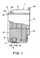
- Figure 1 is a schematic side view of a partially cutaway ink container which stores black ink.
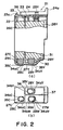
- Figure 2(a) is a schematic side view of a partially cutaway ink container which stores color inks (yellow, cyan, and magenta ink), and Figure 2(b) is a bottom view thereof.
- FIG. 3 is a schematic sectional drawing depicting an example of an ink filling system in accordance with the present invention.
- an ink container is connected to an ink refilling apparatus.
- Figure 4 is a sectional drawing, illustrating the ink delivery member 27Y of the ink container, and the ink discharge member 517Y of the ink refilling apparatus, immediately before they are connected.
- Figure 5 is a graph showing the relationship between the amount of ink consumption and negative static pressure.
- Figure 6 is a schematic sectional drawing depicting an ink refilling system comprising a chicken feeder type ink refilling apparatus in another embodiment of the present invention.
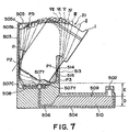
- Figure 7 shows mounting of ink container to an ink refilling apparatus.
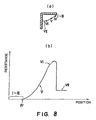
- Figure 8 shows a relationship between positions P5 of the ink container and resistance against insertion thereof during the mounting thereof, wherein (a) shows positions P5 in stages I - VII, and (b) is a graph showing the relationship.
- Figure 1 is a partially cutaway side view of an ink container 1 storing black ink, and depicts the general structure thereof.
- the bottom wall of the ink container is provided with an ink delivery port 8, a rib 15, and slanted portions 14a and 14b.
- the rib 15 surrounds the ink delivery port 8, and they are connected by the slanted portions 14a and 14b.
- the ink reception tube of the ink jet unit 101 on which the ink container is mounted is inserted into the ink delivery port 8.
- ink delivery member 7 formed of a bundle of fiber strands (hereinafter, ink delivery member).
- the provision of a bundle of fiber strands in the ink delivery member 7 is highly effective to stabilize the pressure which is desirable to be present after the ink reception tube of the recording head, which is equipped with a filter, is pressed onto the ink delivery member 7.
- the configuration of the ink delivery member 7 is as shown in Figure 1, for example. That is, the ink delivery member 7 is disposed between the porous member 6 and the ink delivery port 8. It is desirable that the ink delivery member 7 is composed of ink absorbent material, and has a bundle of fiber strands at least on the side which faces the ink container.
- a support member 9 is inwardly erected from the peripheral edge of the ink delivery port 8. A part of the internal surface of the support member 9 is provided with a slit for connecting the internal space of the ink container to the outside.
- An ink delivery member is such a member that guides ink only in one direction. In this embodiment, it guides ink from the porous member toward the ink delivery port 8.
- the porous member disposed in the ink storing portion of the ink container is a piece of ink absorbent material. It is compressed into the ink container.
- the ink absorbent material permeable by ink sponge or the like can be listed, for example.
- the ink delivery member 7 is fixed in its holder portion in the ink container, and is in contact with the porous member 6 compressively disposed in the ink container, maintaining a predetermined contact pressure and thereby, keeping the contact portion of the porous member deformed. This deformation of the porous member increases capillary force, and therefore, ink is concentrated to the adjacencies of the ink delivery member 7.
- ink even after the recording head and the ink container is separated, ink always collects in the ink delivery member 7, and forms meniscus on the surface of the ink delivery member 7, on the side facing the ink delivery port 8. As a result, air is not sucked into the ink container.
- the continuous presence of ink in the adjacencies of the ink delivery member 7 helps ink to flow into the ink delivery member 7, and prevents the ink flow from being interrupted. As a result, the amount of the ink which otherwise will be left unused in the ink container is reduced, improving thereby ink usage efficiency.
- the ink delivery member 7 is composed of strands of fiber.
- Proper material for the ink delivery member 7, which is desired to be chemically stable, and also to be good in wettability, is polyester, nylon, polypropylene, polyethylene, cellulose, polyurethane, and the like.
- metallic fiber glass fiber, carbon fiber, or the like
- the listed materials may be employed in combination.
- the ink delivery member constitutes a part of the ink flow path, it must be given unidirectionality in ink delivery. Further, since it is pressed against the ink reception portion of the recording head, it must have physical strength to retain its original configuration. In order to satisfy the above requirements, fiber strands are desired to be bundled.
- the condition which determines the upper limit for the thickness of the fiber of the ink delivery member is the desired state of contact between the aforementioned filter disposed in the ink reception area, and the ink delivery member.
- the thickness of the fiber is desired to be no more than 0.05 mm.
- the bottom limit for the fiber thickness is desired to be no less than 0.01 mm, in view of the fact that a number of fiber strands are to be bundled to form an ink delivery member, and in order to reduce cost and also to simplify the process for bundling the fiber strands.
- the color ink container 21 containing color inks (in this embodiment, yellow (Y), cyan (C), and'magenta (M) inks) is formed as a single piece ink container integrally comprising sub-containers for these color inks.
- the space within the ink storage shell 22 of the color ink container 21 is partitioned with partition members 36 and 37 which form substantially a letter T.
- the amount of the color ink stored in each sub-space created by the partition members 36 and 37 is the same as those in the other sub-spaces. Dividing the ink container space in this manner makes it possible to dispose the ink delivery port of each sub-container adjacent to the point where three sub-container meet.
- the amount of the ink storable in the ink container can be rendered rather large for the smallness of the projection area of the ink container, and the smallness of the joining space.
- the interior of the ink container 21 is structured in the same manner as the ink container 1 illustrated in Figure 1. That is, ink absorbent porous members 26Y, 26M and 26C are disposed in the corresponding sub-containers, and ink delivery members 27Y, 27M and 27C are disposed between the porous members 26Y, 26M and 26C and the corresponding ink delivery ports 28Y, 28M and 28C.
- a part of the internal surface of each of support member 29Y, 29M and 29C which support the corresponding ink delivery members 27Y, 27M and 27C within the corresponding sub-ink containers, is provided with a slit which connects the internal space of the sub-ink container to the outside.
- a lid 23 is provided with a rib 33 which creates a predetermined amount of space between the porous members 26Y, 26M and 26C and the lid 23.
- the external surface of the lid 23 is provided with a ridge 23a, which is engaged with the overhang portion of the ink jet unit to apply, from above, downward pressure to the ink container 21. This downward pressure keeps the mounted ink container 21 stable.
- FIG. 3 shows an example of the ink refilling system in accordance with the present invention, the system comprising a refilling apparatus 500 and the ink container 21 connected therewith.
- An ink container holding portion (hereinafter, holder) 501 comprises a shell 503, an overhang portion 505, a front plate 513, an ink discharge member 517 (517Y in this drawing), an ink discharge port 507 (507Y in this drawing), and an elastic member 508.
- the ink discharge member 517Y is substantially the same in length as the ink delivery member 27Y of the ink container 21, and is pressed in the ink discharge port 507Y, with its contact tip sticking out of the ink discharge port 507Y.
- the holder also comprises a number of positioning members and the like which allow the ink container 21 to be removably mounted in the holder.
- the bottom portion of the main structure of the ink container refilling apparatus 500 comprises an ink chamber 504, an ink discharge tube 506, and an air entrance 502.
- the ink chamber 504 is to contain ink 510.
- ink is described as yellow ink, and the description given below is also true with cyan (C) ink and magenta (M) ink.
- ink is filled into the ink chamber 504 before the ink discharge member 517Y is pressed into the ink discharge port 507Y. Therefore, ink can be easily filled through the ink discharge port 507Y.
- the ink discharge member 517 is pressed in. Since pressing alone is liable to allow the ink discharge member 517Y to come off during transportation, it is desirable that the ink discharge, member 517 be glued. Simply pressing the ink discharge member 517Y into the ink discharge port 507 does not cause the ink to reach the ink discharge member 517Y; in other words, it does not cause the refilling apparatus to function.
- ink is caused to come in contact with the ink discharge member 517Y by, for example, lifting the right-hand side (air entrance 502 side) of the refilling apparatus, in Figure 3.
- the ink discharge member 517Y is constituted of bundled strands of fiber as those of the ink delivery member 27Y, so that ink is sucked upward into the ink discharge member 517Y, and retained there, by capillary force. Therefore, even after the tilted refilling apparatus is leveled again as it was, ink remains in the ink discharge member 517Y as well as the path thereto from the ink chamber 504. Then, the air entrance 502 is covered with a rubber cap (unillustrated) to prevent ink from leaking.
- the used ink container 21 tries to suck up the ink 510 due to the presence of static negative pressure in the porous member 26 of the ink container 21, but if air remains between the ink meniscus (unillustrated) on the side of the ink discharge member 517Y of the refilling apparatus 500, and the ink meniscus (unillustrated) on the side of the ink delivery member 27Y of the ink container 21, refilling of the used ink container 21 does not occur; therefore, the user has be very sure that these members are directly in contact with each other. Referring to Figure 4, before two ink delivery member 27Y and the ink discharge member 517Y are placed in contact with each other, ink meniscuses 602 and 603 are present on the surfaces (exposed surfaces) of the members.
- Figure 7 illustrate a typical ink container installation sequence, in particular, for the color ink container 21.
- the ink container 21 is picked up by the tab portion, and is inserted into the ink container accommodating portion, as illustrated by a state I.
- the top portion 514 of the front plate 513 is placed in contact with a point (P1) of a lateral wall of the ink container, being used as the guide, and one (P2) of the bottom corners of the ink container is placed in contact with a lateral wall of the casing 503.
- the bottom corner P2 is gradually slid downward, whereby the ink container is rotated about P1, settling in a state illustrated in Figure 7.
- a state III is realized.
- the ink discharge port 507Y is ready to enter the ink delivery port 28Y of the ink container (it should be noted that the ink discharge port 507M is also ready to enter the ink delivery port of the magenta ink container disposed next to the yellow ink container).
- the ink discharge port 507Y comprises therein the aforementioned ink discharge member 517Y constituted of the fiber bundle, the fiber bundle is sometimes damaged through the friction between the fiber bundle and ink delivery port; therefore, it is preferable that the dimensions of the casing and ink container are adjusted so that the ink discharge port does not come in contact with the ink delivery port of the ink container, in the state III, and a state IV, which will be described.
- each ink discharge port comes in contact with the corresponding ink delivery port at a different time, depending on where each ink delivery port is located; therefore, the inclination of its slanted surface is rendered gentler in the order of its contact with the corresponding ink discharge port.
- the yellow and magenta ink containers are provided with a slanted surface having substantially the same inclination, and the slanted surface of the ink delivery port of the cyan ink container is the most inclined.
- the ink delivery port portion is provided with the slanted surface, and its inclination is rendered gentler on the upstream side relative to the direction in which the ink container is inserted into the casing, and is rendered steeper on the opposite side, the ink container can be rotated for the installation, being disposed right next to the port portion, and yet, without causing the ink discharge member 517, which is to be connected to the ink container while the ink container is rotatively inserted in the casing, to interfere with the port portion, and also, the ink delivery port portion can be designed without being expanded more than an ordinary one.
- the bottom portion P3 of the ink container at which the ink container also comes in contact with the casing, slides and shifts toward the font side, causing the ink container to be inclined against the slanted portion of a rib 515, which is provided on the casing 503, on the internal surface of the top portion 514.
- the top corner P5 of the ink container comes in contact with the top end of the slanted portion provided on the shoe portion 505, and begins to generate the insertion resistive feel (state IV illustrated in Figure 7).
- FIG 8 it shows the relation displayed between the location of P5 and the insertion resistive force during the ink container inserting operation.
- the states I - III there is no insertion resistive force since there is no contact between P5 and the casing, as shown in the drawing, and then, in the state IV and thereafter, the resistance gradually increases.
- Figure 7 illustrates a state V in which the insertion has gone further, and in this state, the corner P5 is at a location where the insertion resisting force is much larger than in the state IV, as Figure 14(b) shows.
- the ink container is under a downward pressure effected by the configuration of the slanted portion 505a.
- projections (not shown) provided on the ink container are snappily accelerated toward the internal wall of the casing as they are released, and when they collide with the wall, they generate a "clicking" sound, or a sure feel of clicking, which adds to the feel of the successful completion of the installation. Also at this time, the ink container is pressed downward by the horizontal portion of the pressing means, being surely locked in place.
- the ink delivery member 27Y of the ink container 21 employed in this embodiment of the present invention rubs against the ink reception tube of the image forming apparatus.
- the ink delivery member 27Y of the used ink container 21 is connected to the ink discharge member 517Y of the ink refilling apparatus, they also rub against each other.
- the ink meniscuses 602 and 603 illustrated by the sections of the essential portions of two members in Figure 4 are reliably placed in contact with each other, causing the remaining ink (unillustrated) of the ink container 21 to be united with the ink 510 in the ink chamber 504, and therefore, causing ink refilling to start.
- the material for the ink discharge member 517Y of the refilling apparatus and the material for the ink delivery member 27Y of the ink container are selected so that both materials be substantially similar in function or properties. More specifically, “being similar in function or properties” means being similar in wettability by ink, physical strength, or the like. Therefore, both members are formed of the same material, and are rendered the same in length.
- the ink discharge member 517Y of the refilling apparatus is rendered smaller in external diameter than the ink delivery member 27Y of the ink container, in order to prevent the ink discharge member 517Y from coming in contact with the internal wall of the ink delivery port of the ink container.
- This arrangement can prevent the contamination caused by ink adhesion.
- the density of the ink delivery member 27Y of the ink container is set to render the capillary force of the ink delivery member 27Y larger (for example, -150 mmAq) than that of the porous member of the ink container (generally, -30 mmAq - -100 mmAq) so that ink flow interruption, ink leakage, and the like, can be prevented.
- the density of the ink discharge member 517Y has only to be high enough to create sufficient capillary force (-50 mmAq or so) to prevent the ink flow in the refilling apparatus from being interrupted. Therefore, the density of the ink discharge member 517Y can be reduced, allowing the external diameter thereof to be reduced without increasing the flow resistance. As a result, refilling time can be reduced. Further, in case the ink delivery member and the ink discharge member are the same in density and material, the following occurs. That is, when the strands of fiber in both members perfectly meet the counterparts, the cross-section of the ink path provided by the bundled strands of fiber becomes largest, but when they completely miss the counterparts, the cross-section of the ink path becomes minimum, that is, almost zero. In other words, rendering them different in density is not rendering the cross-section of the ink path smaller, and can reduce the refilling time.
- the ink 510 within the ink chamber 504 is flawlessly sucked up into the ink container 21 by the negative static pressure generated by the ink retaining porous member 26.
- the ink chamber 504 is designed so that the distance E between the ink surface 509 and the bottom surface of the ink delivery member 27Y becomes, for example, 20 mm when the ink surface 509 drops to the minimum level required for flawless ink delivery to the ink container. This is due to the characteristic of the static negative pressure of the ink retaining porous member 26. As ink refilling is repeated, the ink within the ink chamber 504 is reduced, which in turn increases the distance E.
- distance D which is the depth of the ink in the ink chamber 504 is desired to be approximately 10 mm. Therefore, in order to increase the ink capacity of the ink chamber 504, the ink chamber 504 must be designed to be flat as shown in Figure 3.
- Figure 5 shows the relationship between the amount of ink consumption from the ink container and the negative static pressure P.
- the negative static pressure increases as the ink in the ink container is consumed (line I). Then, as the negative pressure reaches a predetermined value (P B ), the ink consumption from the ink container is forced to end (ink flow stops at a point B).
- the ink container is mounted in the ink refilling apparatus after the negative static pressure generated by the porous member 26Y holding yellow ink (Y) and the ink delivery member 27Y reaches the point B in Figure 5.
- the ink in the ink refilling apparatus is united with the remaining ink in the ink container through the ink delivery member 27Y
- the ink stored in the ink chamber 504 is sucked up into the ink container by the negative static pressure P B ( Figure 5) generated by the porous member 26Y and the ink delivery member 27Y.
- the negative static pressure at the tip of the ink container changes in the direction indicated by a line H, which is opposite to the negative pressure change (line I) that occurs while ink is consumed from the ink container.
- FIG 6 illustrates another embodiment of the ink refilling apparatus in accordance-with the present invention.
- This apparatus is similar to the apparatus illustrated in Figure 3 except that this apparatus employs a chicken feeder system to keep the ink level on the ink refilling apparatus side substantially constant. Since this ink refilling apparatus and the ink refilling method used in conjunction with this apparatus are the same as those of the ink refilling apparatus illustrated in Figure 3, matters common to both will be omitted and description will be concentrated on the difference.
- the ink chamber 504 in Figure 6 is provided with an auxiliary ink chamber of a chicken feeder type.
- the tip of the ink delivery tube of the auxiliary ink chamber is disposed to be in contact with the ink surface 509 of the ink chamber 504.
- the top wall of the auxiliary ink chamber is provided with an opening, which is kept sealed with a cap 114C while refilling ink into the ink container, and is opened to fill the auxiliary chamber with ink.
- the air entrance 502 When refilling the auxiliary ink chamber with ink, the air entrance 502 must be covered with the cap 114C. Otherwise, ink will overflow. Further, the height of the auxiliary ink chamber must be regulated so that ink does not leak from the ink discharge member 517Y.
- the ink surface 509 slightly drops, becoming separated from the tip of the ink delivery tube from the auxiliary ink chamber. As a result, the tip of the ink delivery tube is exposed to the outside air, being allowed to take the outside air into the auxiliary ink chamber.
- the outside air enters the auxiliary ink chamber, the ink within the auxiliary ink chamber flows into the ink chamber 504, raising the ink surface 509. Then, as the ink surface 509 rises and comes in contact with the tip of the ink delivery tube, the outside. air is blocked from entering the auxiliary ink chamber through the ink delivery tube. Thus, the level of the ink surface 509 is rendered substantially stable.
- an ink level sensor is unnecessary (provision of a structure capable of preventing the ink level within the auxiliary ink chamber from dropping to zero level is desirable).
- the present invention makes it possible to easily and quickly refill the ink container simply by mounting the ink container in the ink refilling apparatus, without the need for a dangerous device such as a hypodermic needle, without causing ink leakage, and without tying up the user for a long time.
Landscapes
- Ink Jet (AREA)
Claims (7)
- Tintennachfüllsystem zum Nachfüllen von Tinte in einen Tintenbehälter (21), welches einen solchen Tintenbehälter (21) und eine Nachfüllvorrichtung (500) aufweist,
wobei der Tintenbehälter (21) wiederum folgende Elemente aufweist,
ein poröses Element (26) zur Aufnahme von Tinte, welches in der Lage ist, bei Tintenentnahme aus dem Tintenbehälter (21) einen Unterdruck in diesem zu erzeugen, und
einen Tintenzuführstutzen (28Y) zum Speisen des an den Tintenbehälter (21) abnehmbar montierten Aufzeichnungskopfes mit Tinte und
wobei die Nachfüllvorrichtung (500) wiederum folgende Elemente aufweist,
eine Tintenspeichervorrichtung (504, 506) zum Speichern von Nachfülltinte (510) und Speisen des im Tintenbehälter 21) vorhandenen porösen Elements (26) und
ein an der Tintenspeichervorrichtung (504, 506) an deren Tintenbehälteranschlußseite angeordnetes Tintenentnahmeelement (517Y), welches in der Lage ist, Tinte zu absorbieren, und ein Bündel gleichgerichteter Fasern aufweist,
dadurch gekennzeichnet, daß das mit einem Bündel gleichgerichteter Fasern bestückte und ähnliche Benetzbarkeit wie das Tintenentnahmeelement (517Y) aufweisende Tintenzuführelement (27Y) am Tintenzuführstutzen (28Y) angeordnet ist und das poröse Element (26) berührt, wobei nach Verbrauch mindestens eines Teiles der im porösen Element (26) gespeicherten Tinte an der zum Tintenzuführstutzen gerichteten Seite des Tintenzuführelements (27Y) ein Meniskus gebildet wird, und
daß die Nachfüllvorrichtung (500) eine Tintenbehälteraufnahme (501) zur Aufnahme des Tintenbehälters (21) aufweist,
wobei nach dem Einsetzen des Tintenbehälters (21) in die Tintenbehälteraufnahme (501) und durch Andrücken des Tintenzuführelements (27Y) an das Tintenentnahmeelement (517Y) die Strömungsverbindung zwischen der im Tintenzuführelement (27Y) vorhandenen Tinte und der in der Tintenspeichervorrichtung (504, 506) gespeicherten Tinte hergestellt wird, dadurch der am Tintenzuführelement (27Y) vorhandene Meniskus (602) und der an der Berührungsfläche des Tintenentnahmeelements (517Y) vorhandene Meniskus (603) zusammenbrechen und durch den im Tintenbehälter (21) erzeugten Unterdruck Nachfülltinte in diesen gelangt. - System gemäß Anspruch 1 wobei das Tintenzuführelement (27Y) und das Tintenentnahmeelement (517Y) aus dem gleichen Material gefertigt sind.
- System gemäß Anspruch 1, wobei das Tintenentnahmeelement (517Y) und das Tintenzuführelement (27Y) im wesentlichen die gleiche Länge haben.
- System gemäß Anspruch 1, wobei das Tintenzuführelement (27Y) und das Tintenentnahmeelement (517Y) beim Einsetzen des Tintenbehälters relativ zueinander gleiten.
- System gemäß Anspruch 2, wobei die Dichte des Tintenentnahmeelements (517Y) geringer ist als die des Tintenzuführelements (27Y).
- System gemäß Anspruch 1, wobei der Außendurchmesser des Tintenentnahmeelements (517Y) kleiner ist als der des Tintenzuführelements (27Y).
- System gemäß Anspruch 1, wobei der Tintenbehälter (21) so in der Tintenbehälteraufnahme (501) gehalten wird, daß in Schwerkraftrichtung der Tintenzuführstutzen (28) sich unten befindet.
Applications Claiming Priority (6)
| Application Number | Priority Date | Filing Date | Title |
|---|---|---|---|
| JP28989295 | 1995-11-08 | ||
| JP28989295A JP3267488B2 (ja) | 1995-11-08 | 1995-11-08 | インク記録ヘッド用インクタンクのインク再充填装置およびインク再充填方法 |
| JP289892/95 | 1995-11-08 | ||
| JP333160/95 | 1995-12-21 | ||
| JP33316095 | 1995-12-21 | ||
| JP33316095A JP3267493B2 (ja) | 1995-12-21 | 1995-12-21 | インクジェット記録装置及びこれに用いられるインクタンク |
Publications (3)
| Publication Number | Publication Date |
|---|---|
| EP0773109A2 EP0773109A2 (de) | 1997-05-14 |
| EP0773109A3 EP0773109A3 (de) | 1998-03-18 |
| EP0773109B1 true EP0773109B1 (de) | 2002-10-02 |
Family
ID=26557789
Family Applications (1)
| Application Number | Title | Priority Date | Filing Date |
|---|---|---|---|
| EP96117851A Expired - Lifetime EP0773109B1 (de) | 1995-11-08 | 1996-11-07 | Farbstoffnachfüllverfahren und -vorrichtung, Tintenbehälter und Tintenstrahlaufzeichnungsgerät mit einer solchen Vorrichtung |
Country Status (3)
| Country | Link |
|---|---|
| US (2) | US6024442A (de) |
| EP (1) | EP0773109B1 (de) |
| DE (1) | DE69624063T2 (de) |
Families Citing this family (49)
| Publication number | Priority date | Publication date | Assignee | Title |
|---|---|---|---|---|
| JPH10235890A (ja) | 1996-06-25 | 1998-09-08 | Seiko Epson Corp | インクカートリッジ |
| JP3666537B2 (ja) | 1996-11-14 | 2005-06-29 | セイコーエプソン株式会社 | インクジェット式記録装置用インクカートリッジの製造方法 |
| EP1604832A3 (de) * | 1998-02-13 | 2006-02-22 | Seiko Epson Corporation | Druckkopf mit durch ein Rückflussverhinderungsventil verbunder Tankuntereinheit |
| JP3706776B2 (ja) | 1998-09-03 | 2005-10-19 | キヤノン株式会社 | インクタンク、タンクホルダ、インクジェットヘッドカートリッジ、およびインクジェット記録装置 |
| US6390601B1 (en) | 1998-10-27 | 2002-05-21 | Canon Kabushiki Kaisha | Ink tank, ink jet head cartridge, and ink jet recording apparatus |
| US7237884B2 (en) * | 2001-03-30 | 2007-07-03 | Brother Kogyo Kabushiki Kaisha | Ink cartridge |
| US7178911B2 (en) * | 2001-03-30 | 2007-02-20 | Brother Kogyo Kabushiki Kaisha | Ink cartridge |
| JP4193435B2 (ja) * | 2002-07-23 | 2008-12-10 | ブラザー工業株式会社 | インクカートリッジ、および、そのインク充填方法 |
| US7380925B2 (en) * | 2002-03-28 | 2008-06-03 | Brother Kogyo Kabushiki Kaisha | Ink cartridge |
| JP4148498B2 (ja) * | 2002-02-15 | 2008-09-10 | キヤノン株式会社 | 液体噴射記録ヘッドおよび液体噴射記録装置 |
| US6899418B2 (en) | 2002-03-28 | 2005-05-31 | Brother Kogyo Kabushiki Kaisha | Ink cartridge and recording device |
| US6886928B2 (en) * | 2002-03-28 | 2005-05-03 | Brother Kogyo Kabushiki Kaisha | Ink cartridge and method of production thereof |
| EP1348558B1 (de) * | 2002-03-28 | 2004-09-01 | Brother Kogyo Kabushiki Kaisha | Tintenpatrone und Aufzeichnungsgerät |
| US7226153B2 (en) * | 2002-03-28 | 2007-06-05 | Brother Kogyo Kabushiki Kaisha | Ink cartridge |
| USD473895S1 (en) | 2002-08-12 | 2003-04-29 | Yi-Tsung Yan | Refilling clip for inkjet cartridge |
| USD473896S1 (en) | 2002-08-12 | 2003-04-29 | Yi-Tsung Yan | Refilling clip for inkjet cartridge |
| US6789864B2 (en) * | 2002-08-13 | 2004-09-14 | Hewlett-Packard Development Company, L.P. | Systems and methods for refilling printing cartridges |
| ITTO20030302A1 (it) * | 2003-04-17 | 2004-10-18 | Tecnost Sistemi Spa | Dispositivo per custodire e rifornire contemporaneamente |
| ITTO20030303A1 (it) * | 2003-04-17 | 2004-10-18 | Tecnost Sistemi S P A | Stazione di custodia e rifornimento di inchiostro di |
| US7261397B2 (en) * | 2003-08-19 | 2007-08-28 | Canon Kabushiki Kaisha | Tank unit, ink jet recording head and method of manufacturing tank unit and ink jet recording head |
| US7374355B2 (en) * | 2004-01-21 | 2008-05-20 | Silverbrook Research Pty Ltd | Inkjet printer cradle for receiving a pagewidth printhead cartridge |
| US7121655B2 (en) * | 2004-01-21 | 2006-10-17 | Silverbrook Research Pty Ltd | Inkjet printer cartridge refill dispenser |
| US7367650B2 (en) * | 2004-01-21 | 2008-05-06 | Silverbrook Research Pty Ltd | Printhead chip having low aspect ratio ink supply channels |
| US7731327B2 (en) * | 2004-01-21 | 2010-06-08 | Silverbrook Research Pty Ltd | Desktop printer with cartridge incorporating printhead integrated circuit |
| US7425050B2 (en) * | 2004-01-21 | 2008-09-16 | Silverbrook Research Pty Ltd | Method for facilitating maintenance of an inkjet printer having a pagewidth printhead |
| US7232208B2 (en) * | 2004-01-21 | 2007-06-19 | Silverbrook Research Pty Ltd | Inkjet printer cartridge refill dispenser with plunge action |
| US7303255B2 (en) * | 2004-01-21 | 2007-12-04 | Silverbrook Research Pty Ltd | Inkjet printer cartridge with a compressed air port |
| US7469989B2 (en) * | 2004-01-21 | 2008-12-30 | Silverbrook Research Pty Ltd | Printhead chip having longitudinal ink supply channels interrupted by transverse bridges |
| US7097291B2 (en) * | 2004-01-21 | 2006-08-29 | Silverbrook Research Pty Ltd | Inkjet printer cartridge with ink refill port having multiple ink couplings |
| US7448734B2 (en) | 2004-01-21 | 2008-11-11 | Silverbrook Research Pty Ltd | Inkjet printer cartridge with pagewidth printhead |
| US7645025B2 (en) * | 2004-01-21 | 2010-01-12 | Silverbrook Research Pty Ltd | Inkjet printer cartridge with two printhead integrated circuits |
| US7364263B2 (en) * | 2004-01-21 | 2008-04-29 | Silverbrook Research Pty Ltd | Removable inkjet printer cartridge |
| US7441865B2 (en) * | 2004-01-21 | 2008-10-28 | Silverbrook Research Pty Ltd | Printhead chip having longitudinal ink supply channels |
| US20050157112A1 (en) * | 2004-01-21 | 2005-07-21 | Silverbrook Research Pty Ltd | Inkjet printer cradle with shaped recess for receiving a printer cartridge |
| JP4468192B2 (ja) * | 2005-01-27 | 2010-05-26 | キヤノン株式会社 | インクジェット記録装置 |
| US7467852B2 (en) * | 2005-12-05 | 2008-12-23 | Silverbrook Research Pty Ltd | Inkjet printer with printhead cartridge and ink cartridge |
| US7431440B2 (en) * | 2005-12-05 | 2008-10-07 | Silverbrook Research Pty Ltd | Ink reservoir with air bag |
| US7556364B2 (en) | 2005-12-05 | 2009-07-07 | Silverbrook Research Pty Ltd | Ink cartridge with self sealing outlet valve |
| US7357496B2 (en) * | 2005-12-05 | 2008-04-15 | Silverbrook Research Pty Ltd | Inkjet printhead assembly with resilient ink connectors |
| JP2008087218A (ja) * | 2006-09-29 | 2008-04-17 | Brother Ind Ltd | インクジェットプリンタ |
| DE202007019225U1 (de) * | 2007-08-06 | 2011-05-05 | Pelikan Hardcopy Production Ag | Vorrichtung zur Wiederbefüllung einer Tintenpatrone für einen Tintenstrahldrucker |
| US20090071564A1 (en) * | 2007-09-19 | 2009-03-19 | William Jon Rittgers | Filling An Ink Pen |
| JP5006812B2 (ja) * | 2008-02-15 | 2012-08-22 | キヤノン株式会社 | インクタンクおよびインクジェットカートリッジ |
| DE102008010506A1 (de) * | 2008-02-22 | 2009-08-27 | Pelikan Hardcopy Production Ag | Verfahren und Vorrichtung zur Wiederbefüllung einer Tintenpatrone für einen Tintenstrahldrucker |
| JP5067876B2 (ja) * | 2008-04-21 | 2012-11-07 | キヤノン株式会社 | インクジェット記録装置 |
| CN102264870B (zh) * | 2008-12-23 | 2014-01-08 | 英特卡设备有限公司 | 调节一个或多个单元中物质存量的物质回收装置和方法 |
| US20120176452A1 (en) * | 2011-01-12 | 2012-07-12 | Zhuhai Ninestar Management Co., Ltd. | Method for refilling ink into ink cartridge and filling tool |
| CN102963132A (zh) * | 2012-11-27 | 2013-03-13 | 嘉兴天马打印机耗材有限公司 | 墨盒添墨方法 |
| JP6498098B2 (ja) | 2015-10-30 | 2019-04-10 | キヤノン株式会社 | 記録装置および液体収容部材 |
Family Cites Families (15)
| Publication number | Priority date | Publication date | Assignee | Title |
|---|---|---|---|---|
| JPS5968985A (ja) * | 1982-10-13 | 1984-04-19 | Mitsubishi Electric Corp | 無声放電式ガスレ−ザ装置 |
| JPS61158465A (ja) * | 1984-12-28 | 1986-07-18 | Canon Inc | インクジエツト記録装置 |
| US4967207A (en) * | 1989-07-26 | 1990-10-30 | Hewlett-Packard Company | Ink jet printer with self-regulating refilling system |
| DE69031872T2 (de) | 1989-09-18 | 1998-04-30 | Canon Kk | Methode zum Füllen einer Tintenpatrone für Tintenstrahlaufzeichnungsgeräte |
| ATE139941T1 (de) * | 1990-02-26 | 1996-07-15 | Canon Kk | Tintenstrahlaufzeichnungsgerät und verfahren zum reinigen des aufzeichnungskopfes |
| US5280300A (en) * | 1991-08-27 | 1994-01-18 | Hewlett-Packard Company | Method and apparatus for replenishing an ink cartridge |
| IT1250519B (it) * | 1991-10-10 | 1995-04-08 | Olivetti & Co Spa | Dispositivo per il rifornimento dell'inchiostro a una testina di stampa a getto d'inchiostro e relativo metodo di rifornimento. |
| JP2788685B2 (ja) | 1991-10-21 | 1998-08-20 | シャープ株式会社 | インクカ−トリッジ、インク受給部、及びインク供給装置 |
| JP3110872B2 (ja) * | 1992-06-24 | 2000-11-20 | キヤノン株式会社 | インクジェット記録装置 |
| IT1258135B (it) * | 1992-12-28 | 1996-02-20 | Olivetti Canon Ind Spa | Dispositivo per conservare e mantenere rifornite d'inchiostro le cartucce di una stampante a getto d'inchiostro. |
| JP3222294B2 (ja) * | 1993-01-01 | 2001-10-22 | キヤノン株式会社 | インク再充填容器及び該容器を用いたインク再充填方法 |
| DE9302401U1 (de) | 1993-02-19 | 1993-06-17 | Hoechst Ag, 65929 Frankfurt | Granulat aus faserverstärktem Thermoplast |
| DE69424724T2 (de) * | 1993-08-31 | 2000-11-23 | Canon K.K., Tokio/Tokyo | Verfahren und Gerät zum Befüllen von Tintenpatronen mit Tinte |
| US5369429A (en) * | 1993-10-20 | 1994-11-29 | Lasermaster Corporation | Continuous ink refill system for disposable ink jet cartridges having a predetermined ink capacity |
| EP0699532B1 (de) * | 1994-08-31 | 2000-06-28 | Canon Kabushiki Kaisha | Farbstoffnachfüllverfahren und -vorrichtung für Farbstoffbehälter |
-
1996
- 1996-11-07 EP EP96117851A patent/EP0773109B1/de not_active Expired - Lifetime
- 1996-11-07 DE DE69624063T patent/DE69624063T2/de not_active Expired - Lifetime
- 1996-11-08 US US08/747,079 patent/US6024442A/en not_active Expired - Lifetime
-
1999
- 1999-10-22 US US09/422,787 patent/US6338552B1/en not_active Expired - Lifetime
Also Published As
| Publication number | Publication date |
|---|---|
| EP0773109A2 (de) | 1997-05-14 |
| EP0773109A3 (de) | 1998-03-18 |
| US6338552B1 (en) | 2002-01-15 |
| US6024442A (en) | 2000-02-15 |
| DE69624063D1 (de) | 2002-11-07 |
| DE69624063T2 (de) | 2003-02-13 |
Similar Documents
| Publication | Publication Date | Title |
|---|---|---|
| EP0773109B1 (de) | Farbstoffnachfüllverfahren und -vorrichtung, Tintenbehälter und Tintenstrahlaufzeichnungsgerät mit einer solchen Vorrichtung | |
| US9592675B2 (en) | Liquid fill container | |
| CN105774255B (zh) | 液体收纳容器和液体喷射系统 | |
| KR100390126B1 (ko) | 프린팅시스템및프린트카트리지보충방법 | |
| EP0633138B1 (de) | Tintenzuführvorrichtung | |
| EP1199178B1 (de) | Tintenpatrone für Tintenstrahlaufzeichnungsgerät | |
| KR100233977B1 (ko) | 잉크보충 시스템과 잉크제트 프린트 카트리지의 보충방법 및 프린트 카트리지 보충 시스템 이용방법 | |
| KR100235282B1 (ko) | 잉크제트 인쇄 시스템과 잉크제트 프린트 카트리지를 이용한 잉크보충방법 | |
| GB2293142A (en) | Capillary regulation of ink flow in multi-chambered ink cartridge for ink jet printer. | |
| JP6264328B2 (ja) | 液体補充容器 | |
| EP3718772B1 (de) | Tintenstrahldruckvorrichtung und tintentank | |
| JPH06255122A (ja) | インクジェット記録装置のインク供給装置 | |
| CN102336062B (zh) | 液体收纳容器、液体喷射系统以及液体供给系统 | |
| EP0921005B1 (de) | Einrichtung und Verfahren zur Lüftung eines Tintenbehälters | |
| JPH10250098A (ja) | インク供給装置及びインク充填方法 | |
| GB2315462A (en) | Ink cartridge having tapered bore | |
| US11833833B2 (en) | Liquid container and liquid ejection apparatus | |
| JP3224180B2 (ja) | インク記録ヘッド用インクタンクのインク再充填方法および再充填装置 | |
| JPH09131886A (ja) | インク記録ヘッド用インクタンクのインク再充填装置 | |
| JPS58199159A (ja) | インクジェット記録装置 | |
| JPH023320A (ja) | インクジェット記録装置 | |
| JP3219624B2 (ja) | インク記録ヘッド用インクタンクのインク再充填装置 | |
| JP7483961B2 (ja) | 記録装置 | |
| JPH0768782A (ja) | インクジェットヘッドカートリッジ | |
| JPH09169119A (ja) | インクジェット記録装置 |
Legal Events
| Date | Code | Title | Description |
|---|---|---|---|
| PUAI | Public reference made under article 153(3) epc to a published international application that has entered the european phase |
Free format text: ORIGINAL CODE: 0009012 |
|
| 17P | Request for examination filed |
Effective date: 19961107 |
|
| AK | Designated contracting states |
Kind code of ref document: A2 Designated state(s): CH DE FR GB IT LI |
|
| PUAL | Search report despatched |
Free format text: ORIGINAL CODE: 0009013 |
|
| AK | Designated contracting states |
Kind code of ref document: A3 Designated state(s): CH DE FR GB IT LI |
|
| 17Q | First examination report despatched |
Effective date: 19991206 |
|
| GRAG | Despatch of communication of intention to grant |
Free format text: ORIGINAL CODE: EPIDOS AGRA |
|
| GRAG | Despatch of communication of intention to grant |
Free format text: ORIGINAL CODE: EPIDOS AGRA |
|
| GRAH | Despatch of communication of intention to grant a patent |
Free format text: ORIGINAL CODE: EPIDOS IGRA |
|
| GRAH | Despatch of communication of intention to grant a patent |
Free format text: ORIGINAL CODE: EPIDOS IGRA |
|
| GRAA | (expected) grant |
Free format text: ORIGINAL CODE: 0009210 |
|
| AK | Designated contracting states |
Kind code of ref document: B1 Designated state(s): CH DE FR GB IT LI |
|
| REG | Reference to a national code |
Ref country code: GB Ref legal event code: FG4D |
|
| REG | Reference to a national code |
Ref country code: CH Ref legal event code: NV Representative=s name: BOVARD AG PATENTANWAELTE Ref country code: CH Ref legal event code: EP |
|
| REF | Corresponds to: |
Ref document number: 69624063 Country of ref document: DE Date of ref document: 20021107 |
|
| ET | Fr: translation filed | ||
| PLBE | No opposition filed within time limit |
Free format text: ORIGINAL CODE: 0009261 |
|
| STAA | Information on the status of an ep patent application or granted ep patent |
Free format text: STATUS: NO OPPOSITION FILED WITHIN TIME LIMIT |
|
| 26N | No opposition filed |
Effective date: 20030703 |
|
| PGFP | Annual fee paid to national office [announced via postgrant information from national office to epo] |
Ref country code: IT Payment date: 20081119 Year of fee payment: 13 |
|
| PGFP | Annual fee paid to national office [announced via postgrant information from national office to epo] |
Ref country code: FR Payment date: 20081124 Year of fee payment: 13 |
|
| REG | Reference to a national code |
Ref country code: FR Ref legal event code: ST Effective date: 20100730 |
|
| PG25 | Lapsed in a contracting state [announced via postgrant information from national office to epo] |
Ref country code: FR Free format text: LAPSE BECAUSE OF NON-PAYMENT OF DUE FEES Effective date: 20091130 |
|
| REG | Reference to a national code |
Ref country code: CH Ref legal event code: PFA Owner name: CANON KABUSHIKI KAISHA Free format text: CANON KABUSHIKI KAISHA#30-2, 3-CHOME, SHIMOMARUKO, OHTA-KU#TOKYO (JP) -TRANSFER TO- CANON KABUSHIKI KAISHA#30-2, 3-CHOME, SHIMOMARUKO, OHTA-KU#TOKYO (JP) |
|
| PG25 | Lapsed in a contracting state [announced via postgrant information from national office to epo] |
Ref country code: IT Free format text: LAPSE BECAUSE OF NON-PAYMENT OF DUE FEES Effective date: 20091107 |
|
| PGFP | Annual fee paid to national office [announced via postgrant information from national office to epo] |
Ref country code: CH Payment date: 20131125 Year of fee payment: 18 |
|
| PGFP | Annual fee paid to national office [announced via postgrant information from national office to epo] |
Ref country code: GB Payment date: 20141124 Year of fee payment: 19 Ref country code: DE Payment date: 20141130 Year of fee payment: 19 |
|
| REG | Reference to a national code |
Ref country code: CH Ref legal event code: PL |
|
| PG25 | Lapsed in a contracting state [announced via postgrant information from national office to epo] |
Ref country code: CH Free format text: LAPSE BECAUSE OF NON-PAYMENT OF DUE FEES Effective date: 20141130 Ref country code: LI Free format text: LAPSE BECAUSE OF NON-PAYMENT OF DUE FEES Effective date: 20141130 |
|
| REG | Reference to a national code |
Ref country code: DE Ref legal event code: R119 Ref document number: 69624063 Country of ref document: DE |
|
| GBPC | Gb: european patent ceased through non-payment of renewal fee |
Effective date: 20151107 |
|
| PG25 | Lapsed in a contracting state [announced via postgrant information from national office to epo] |
Ref country code: DE Free format text: LAPSE BECAUSE OF NON-PAYMENT OF DUE FEES Effective date: 20160601 Ref country code: GB Free format text: LAPSE BECAUSE OF NON-PAYMENT OF DUE FEES Effective date: 20151107 |