EP0773110A2 - Ensemble de cassette à bande et appareil d'impression - Google Patents
Ensemble de cassette à bande et appareil d'impression Download PDFInfo
- Publication number
- EP0773110A2 EP0773110A2 EP96114988A EP96114988A EP0773110A2 EP 0773110 A2 EP0773110 A2 EP 0773110A2 EP 96114988 A EP96114988 A EP 96114988A EP 96114988 A EP96114988 A EP 96114988A EP 0773110 A2 EP0773110 A2 EP 0773110A2
- Authority
- EP
- European Patent Office
- Prior art keywords
- tape
- tape cassette
- cassette
- type
- image
- Prior art date
- Legal status (The legal status is an assumption and is not a legal conclusion. Google has not performed a legal analysis and makes no representation as to the accuracy of the status listed.)
- Granted
Links
- 238000007639 printing Methods 0.000 title claims abstract description 60
- 238000010017 direct printing Methods 0.000 claims abstract description 17
- 230000003993 interaction Effects 0.000 claims abstract description 8
- 238000003780 insertion Methods 0.000 claims abstract description 3
- 230000037431 insertion Effects 0.000 claims abstract description 3
- 238000007651 thermal printing Methods 0.000 claims description 18
- 230000007246 mechanism Effects 0.000 claims description 8
- 230000005540 biological transmission Effects 0.000 claims description 7
- 238000001514 detection method Methods 0.000 claims description 2
- 239000010410 layer Substances 0.000 description 9
- 239000012790 adhesive layer Substances 0.000 description 5
- 239000000758 substrate Substances 0.000 description 4
- 238000013479 data entry Methods 0.000 description 3
- 238000005520 cutting process Methods 0.000 description 2
- 230000004913 activation Effects 0.000 description 1
- 230000008901 benefit Effects 0.000 description 1
- 230000006870 function Effects 0.000 description 1
- 238000000034 method Methods 0.000 description 1
Images


Classifications
-
- B—PERFORMING OPERATIONS; TRANSPORTING
- B41—PRINTING; LINING MACHINES; TYPEWRITERS; STAMPS
- B41J—TYPEWRITERS; SELECTIVE PRINTING MECHANISMS, i.e. MECHANISMS PRINTING OTHERWISE THAN FROM A FORME; CORRECTION OF TYPOGRAPHICAL ERRORS
- B41J3/00—Typewriters or selective printing or marking mechanisms characterised by the purpose for which they are constructed
- B41J3/407—Typewriters or selective printing or marking mechanisms characterised by the purpose for which they are constructed for marking on special material
- B41J3/4075—Tape printers; Label printers
Definitions
- the invention relates to a set of tape cartridges, and more particularly, to an image receiving tape cartridge in connection with an image transfer tape cartridge or a thermal direct printing tape cartridge usable in a thermal printing apparatus.
- General pressure devices with which the present invention is concerned are known. They work with a supply of tapes to be recorded and a means of transferring the image to the tape.
- a tape cassette contains a supply of image receiving tape and a supply of image transfer tape, the image receiving tape and the image transfer tape being guided in mutual overlap through a printing zone of the printing device.
- a thermal print head interacts with a counter-pressure roller in order to transfer an image from the image transfer belt to the image receiving belt.
- a printing device working with a tape cassette of the aforementioned type is for example in EP-A-0267890 (Varitronics, Inc.).
- Further printing devices have been manufactured in which letters are transferred to an image receiving tape by means of a dry lettering or dry film printing method. In all of these printing devices, the structure of the image receiving tape is essentially the same. This means that it consists of an upper, image-receiving layer which is attached to a releasable backing layer by means of an adhesive layer.
- the releasable backing layer is removed from the top layer in order to be able to attach the top layer to a surface by means of the adhesive layer.
- a tape cassette contains a supply of a transparent image receiving tape and a supply of an image transfer tape.
- the tape cassette also contains a supply of backing tape which includes a backing having an adhesive layer on its underside to which a peelable backing paper is attached and an adhesive layer on its top which is attachable to the image receiving tape after an image has been printed thereon .
- the image is printed as a mirror image on the image receiving tape, which appears the right way round when you look through the image receiving tape. With this device, the print is protected when the label is used.
- the color of the print and the label are predetermined by the content of the tape cassette.
- the color of the label relates to the top layer of the image receiving tape of the device described in EP-A-0267890 and the backing layer of the device described in relation to EP-A-0322919.
- the color of the print is determined by the color of the image transfer belt. This means that labels of a certain color can only be printed with ink of a certain color. Furthermore, they will end together because the image receiving tape and the image transfer tape are contained in a common tape cassette.
- Another device has two ribbon cartridges, an ink ribbon cartridge is nest-like within a substrate ribbon cartridge on a common side of the print zone. This means that it is tricky and difficult to remove the ink ribbon cartridge for replacement. Furthermore the outer dimensions of the ink ribbon cassette are determined by the dimensions of the substrate ribbon, so that their size or capacity could only be increased at the expense of the substrate ribbon.
- a printing device which solves the above problems is known from EP-A-0573187.
- This document discloses a printing device having first and second tape cassette receiving areas located on opposite sides of a printing zone.
- the first tape cassette receiving area is used to receive a tape cassette that contains a supply of image transfer tape.
- the second tape cassette receiving area is used to receive a tape cassette that contains a supply of image receiving tape. In this way, the first and second tape cassettes can be removed and replaced individually.
- This pressure device has a wide range of applications. However, it has the limitation that the currently available widths of the image receiving tape have a maximum width of 19 mm. 6 mm, 12 mm and 19 mm widths of the image reception band are currently available. These all work together with an image transfer belt with a width of 19 mm. However, it is desirable to provide image receiving tape of larger widths, for example 24 mm and 32 mm. Obviously, the 19 mm wide image transfer belt is not wide enough to fully expand the 24 mm or 32 mm wide image receiving belt. It is therefore desirable to provide a tape cassette with an image transfer tape which has a larger width.
- a set of tape cassettes comprising at least two tape cassettes of a first type and two tape cassettes of a second type, tape cassettes of the first type containing image receiving tape with different tape parameters in each case and tape cartridges of the second type containing image transfer tape with different tape parameters in each case, and wherein each of the first type of tape cassettes has a first cooperation means depending on the tape parameter of the image receiving tape, and each of the second type tape cassettes has a second cooperation means depending on the tape parameter of the image transfer belt, the first and second cooperation means being arranged to selectively cooperate with each other and only allow a properly selected tape cassette of the second type to cooperate with the tape cassettes of the first type, and otherwise to cooperate the tape cassette exclude.
- the band parameter is the width of the band. It is also possible to share the invention with others Use tape parameters such as color or type of image receiving tape or transfer tape to ensure that only properly matching tapes can work together.
- One of the first and second cooperation means can comprise a component projecting from the tape cassette, the shape of which depends on the parameter of the tape.
- the respective other of the first and second interaction means can be an incision made in the tape cassette, the shape of which depends on the parameter of the tape and is designed such that only the component of the properly selected tape cassette can be accommodated therein.
- image transfer belt is provided in two widths of 19 mm and 28 mm.
- the width of 19 mm is suitable for use with image receiving tape with a width of 6 mm, 12 mm and 19 mm.
- the width of 28 mm of the image transfer belt is suitable for the use of image receiving tape with a width of 24 mm or 32 mm.
- a thermal printing device is also provided with a first tape cassette receiving area for receiving a first tape cassette, the one Includes a supply of image receiving tape, a second tape cassette receiving area for receiving a second tape cassette containing a supply of image transfer tape for printing an image; Means for moving the image receiving tape through a printing zone in superimposition with the image transfer tape so that an image can be transferred from the image transfer tape to the image receiving tape, the first and second tape cassettes each being selectable from first and second groups such that they can be removed and replaced individually, the groups forming a set of tape cartridges as described above.
- each tape cassette can easily be removed and inserted separately without influencing the other. Since each tape cassette is housed separately, there is no need to take the other out so that they can be removed, mixed and used as desired, only depending on the selection of a proper type of image transfer tape for a selected image receiving tape. Furthermore, the size and capacity of each tape cartridge is determined only by the tape cartridge receiving areas and not by the other tape cartridge.
- a printing device of the above type can operate without a thermal transfer ribbon.
- the image receiving tape could be a so-called direct thermal printing tape onto which an image can be printed by the generation of heat, but without the interposition of a thermal transfer ink ribbon. If a tape cartridge with a If direct thermal ribbon of this type were to be inserted into a printing device, it would be advantageous to exclude the possibility of inserting a ribbon cassette with an image transfer ribbon at the same time.
- a thermal printing device is proposed with a first tape cassette receiving area for receiving a first tape cassette which contains a supply of image receiving tape which is to be printed with an image; a second tape cassette receiving area for receiving a second tape cassette containing a supply of image transfer tape; Means for moving the image-receiving tape through a print zone in which a thermal printing mechanism operates to print an image on the image-receiving tape, the first tape cassette being selectable from a set of tape cassettes comprising at least one tape cassette containing a supply of direct thermal printing tape, wherein the tape cassette with thermal direct printing tape is shaped such that it precludes the insertion of a second tape cassette into the second tape cassette receiving area; and wherein the first tape cassette receiving area comprises means for detecting that a first tape cassette with thermal direct printing tape is inserted.
- a tape cassette with thermal direct printing tape is preferably provided with a component projecting from the housing so that, when inserted, it extends into the second tape cassette receiving area in order to exclude the possibility of using a tape cassette with image transfer tape.
- the invention further provides a set of tape cassettes comprising at least one tape cassette containing thermal direct printing tape, a tape cassette containing image receiving tape, and a tape cassette containing image transfer tape, the tape cassette with image receiving tape and the tape cassette with image transfer tape each containing cooperating means in order to be able to use them together in a printing device, and the tape cassette with thermal direct printing tape is designed in such a way that the possibility of using it together with a tape cassette with image transfer tape in the printing device is excluded.
- set of tape cartridges and the thermal printing device according to the first aspect of the invention can incorporate features of the second aspect of the invention, and vice versa.
- FIG. 1 shows the view of a tape printing device 1 in which the present invention is used and which contains two tape cassettes arranged therein.
- the upper tape cassette 2 is arranged in a first tape cassette receiving area 26 and contains a supply of image receiving tape 54 which is guided through a printing zone 3 of the tape printing device 1 to an outlet 5 of the tape printing device 1.
- the image receiving tape 54 includes an upper layer for receiving a printed image on one of its surfaces, while its other surface is coated with an adhesive layer to which a peelable backing layer is applied.
- the tape cassette 2 has an incision 6 for receiving a pressure roller 8 of the tape printing device 1, and guide sections 22, 24 for guiding the tape 54 through the printing zone 3.
- the pressure roller 8 is rotatably arranged within a cast cage 10. Alternatively, the pressure roller 8 can be rotatably arranged on a pin.
- the lower ribbon cassette 4 is arranged within a second ribbon cassette receiving area 28 and contains, as an image transfer ribbon, a thermal transfer ink ribbon 12 which extends from a supply reel 30 to a take-up reel 32 within the ribbon cassette 4.
- the thermal transfer ribbon 12 extends through the printing zone 3 in overlap with the image receiving ribbon 54.
- the ribbon cassette 4 has an incision 14 for receiving a printhead 16 of the ribbon printing device 1 and guide sections 34, 36 for guiding the thermal transfer ribbon 12 through the printing zone 3.
- the printhead 16 is between an operating position, which is shown in Figure 1, in which it is in contact with the printing roller 8 and the thermal transfer ribbon 12 and the image receiving ribbon 54 overlap between the print head 16 and the printing roller 8, and an inoperative position, in which it from the Print roller 8 is moved to release the thermal transfer ribbon 12 and the image receiving ribbon 54, movable.
- the platen roller 8 In the operating position, the platen roller 8 is rotatably driven to transport the image receiving tape 54 along the print head 16, while the print head 16 is driven to print an image on the image receiving tape 54 by thermal transfer of the ink of the ink ribbon 12.
- Printhead 16 is a conventional thermal printhead with a number of print elements that correspond of the desired image to be printed out can be thermally activated.
- the tape printing device 1 has a lid, which is not shown, but is pivotally attached to the back of the tape cassette receiving section 26 and which covers both tape cassettes 2, 4 in the closed state.
- a motor drives the platen 8 while successively printing rows on the image receiving belt 54.
- the printing roller 8 continuously drives the image receiving belt 4 through the printing zone 3 through the application of its torque.
- the rotation of the platen 8 and the activation of the printhead 16 are controlled by a microprocessor as described, for example, in our European patent applications 0578372 and 0580322, the contents of which are incorporated herein by reference.
- Figure 1 represents the prior art as it is known from EP-A-0573187. It is obvious that tape cassettes 2 with image receiving tape 54 of different tape parameters can be used arbitrarily with tape cassettes 4 with image transfer tape 12 of different tape parameters, so that incorrect operation can sometimes not be excluded. For example, a very wide image reception belt 54 with a very narrow image transmission belt 12 can be used inadvertently.
- FIG. 2 shows the basic control circuit for controlling the tape printing device 1.
- a microprocessor chip 100 which includes a read only memory (ROM) 102, a microprocessor 101 and freely accessible memory capacity which is represented by a RAM 104.
- the microprocessor 101 is connected to a data entry device, such as a keyboard 106, for receiving data input thereto.
- the microprocessor chip 100 outputs data for driving a display 108 via a display driver chip 109, and also data for driving the print head 16 and the motor 7 for controlling the printing roller 8.
- the microprocessor chip 100 also controls the cutting mechanism 17 to cut lengths of printed tape.
- the keyboard and display are located on the top surface of the printing device on the right side of the tape cassette accommodating space, as indicated by the broken lines.
- Reference numeral 19 represents a tape cassette diagnostic device which includes switches in the tape cassette accommodating rooms for the detection of various tape cassette conditions, as will be described in more detail below.
- Data to be printed is entered into the printing device using data entry keys on the keyboard 106.
- the data entry keys are generally represented by block 109, but will in practice include a plurality of lettered and numbered keys.
- the microprocessor calls a stored one for each character entered Form of the character from the ROM 102 onwards. Since the character is stored in compressed form, this font data is temporarily stored in RAM 104 and manipulated by microprocessor 100 to produce pixel data to generate the character.
- This pixel data is transmitted in one form to the display 108 and in another form for printing to the printhead. Character data is not sent to the printhead unless a print operation is in progress.
- the characters for the label are entered and changed using function keys on the keyboard 106 in conjunction with the display 108.
- the microprocessor knows the pixel data to be printed and has also calculated the total length of the label.
- a series of pixel data is transferred to the printhead which prints that series on the image receiving tape.
- the motor then advances the image receiving tape the width of one row and the data of the next row is transferred to the print head and printed.
- the motor moves the image receiving tape a distance that is the distance between the printhead and a zone where a cut is set up. Then, a cutting operation is performed by the cutter 17 to cut off the printed portion of the tape that forms the label.
- FIG. 3 shows a tape cassette 4a which is similar to the tape cassette 4 in FIG. 1.
- FIG. 3 also discloses a tape cassette 2a which is similar to the tape cassette 2 in FIG. 1.
- the tape cassette 4a is substantially the same as that described in relation to FIG. 1, but includes a locking element 50 which extends from the housing of the tape cassette 4a.
- the locking element 50 ends in a hook-shaped section 52.
- the tape cassette 2a is similar to that described with reference to FIG. 1, but contains in its housing an incision 54 which is dimensioned to accommodate the hook-shaped section 52.
- the incision 54 has an edge 56, above which the hook-shaped section 52 of the locking element 50 is arranged.
- the image transmission belt has a width of 19 mm and the image reception belt has a width of 6 mm or 12 mm.
- the locking element 50 interacts with the incision 54 in order to enable these tape cassettes to work together in the printing device.
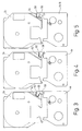
- FIG. 4 illustrates another set of tape cartridges.
- the tape cassette 4b shown in FIG. 4 is similar to the tape cassette 4a, with the exception that it contains image transfer tape of a larger width, for example 28 mm. It is also provided with a locking element 58, which has a hook-shaped section 60 which is closer to the surface of the tape cassette 4b than the hook-shaped section 52 of the locking element 50 in FIG. 3.
- the tape cassette 2b is similar to the tape cassette 2a of FIG. 3, but contains an image receiving tape of a larger width, for example 24 mm or 32 mm.
- the tape cassette 2b has an incision 62 which receives the locking element 58, but which does not define an edge. In this way, the set of tape cartridges of Figure 4 is allowed to cooperate.
- FIG. 5 shows a set of tape cassettes, the tape cassette containing an image receiving tape 19 mm wide. This could easily interact with an image transfer belt 19mm or 28mm wide.
- the tape cassette 2c contains a so-called double notch 64. This double notch 64 will accommodate both the locking element 58 of the tape cassette 4b and the locking element 50 of the tape cassette 4a.
- the tape cassette with image transfer tape marked with 4a / b in FIG. This indicates that each of the tape cassettes could properly cooperate with a tape cassette 2c with a tape width of 19 mm.
- Figure 6 illustrates a tape cassette 2d containing thermal direct printing tape.
- the tape cassette has an elongated section 60 that extends into the second tape cassette receiving area 28 when the tape cassette 2d is inserted into the first tape cassette receiving area 26. It is therefore physically not possible to insert a tape cassette into the second tape cassette receiving area if a tape cassette with a thermal direct printing tape is inserted.
- a tape cassette 2d with thermal direct printing tape has an actuator 62 for actuating a switching mechanism in the first tape cassette receiving area 26 to indicate that a thermal direct printing tape has been inserted.
- the switching mechanism in the first tape cassette receiving area 26 is contained in the tape cassette diagnostic device 19.
- a signal is sent to the controller 100 to indicate that a thermal direct print tape cartridge is loaded and the controller changes the print energy for the printhead 16 accordingly. If necessary, further changes to the operation of the printing device can be made.
- FIGS. 7a to 7d and 8a to 8d Another aspect of the tape cassette 2d of FIG. 6 will now be explained with reference to FIGS. 7a to 7d and 8a to 8d.
- a switch located in the second tape cassette receiving area detects when a lid of the printing device is closed and when a tape cassette with image transfer tape is present, so that the device only works when both Criteria are met. Such a device would not work if no tape cassette with an image transfer tape were used.
- the tape cassette 2d with direct thermal printing tape is also designed to operate the same switch, so that the controller 100 appears to have a tape cassette with an image transfer tape so that the device operates.
- the switch is generally designated by reference numeral 202 ( Figure 8a). It is carried by a print head arm 204, which also carries the print head 16. The printhead arm is attached to the cover 206 of the printing device via an actuating mechanism 208, the details of which are not shown here. In short, the printhead is moved to its inoperative position when the lid is open. When the lid is closed, the print head is brought into its operating position. As the printhead arm 204 moves between the operating position and the non-operating position, the switch moves with it. Numeral 210 indicates a switch actuator again, which is arranged at the bottom of the second tape cassette receiving space. Figures 7a and 8a illustrate the position when the lid is open and no tape cassette with image transfer tape is inserted.
- FIGS. 7b and 8b show the position when the cover 206 is closed and there is still no tape cassette with an image transfer tape. In this situation, the position of the switch 202 with the print head arm 204 has changed, but the contacts are not yet in contact. Thus, switch 202 remains open and controller 100 does not allow the device to operate.
- Figures 7c and 8c illustrate the situation when a tape cassette with image transfer tape is inserted in the second tape cassette receiving area with the lid 206 in the open position.
- the tape cassette can be a tape cassette with image transfer tape or a tape cassette 2d with direct thermal printing tape, with the extended section 60 acting on the switch actuator 210.
- the switch actuator 210 is moved elastically to the right in FIG. 7c in order to bring it into a position in which it now prevents the switch 202 from moving too far to the left in FIG. 8c.
- the cover 206 is open and therefore the contacts of the switch 202 are not closed.
- the switch 202 is moved such that it abuts the switch actuator 210 so that the contacts of the switch 202 are closed when the cover 206 is closed and printhead arm 204 is moving. The pressure device will work in this position.
Landscapes
- Impression-Transfer Materials And Handling Thereof (AREA)
- Handling Of Continuous Sheets Of Paper (AREA)
Priority Applications (2)
| Application Number | Priority Date | Filing Date | Title |
|---|---|---|---|
| EP01106197A EP1106367B8 (fr) | 1995-11-10 | 1996-09-19 | Ensemble de cassette à bande et appareil d'impression |
| DE59611319T DE59611319D1 (de) | 1995-11-10 | 1996-09-19 | Satz von Bandkassetten und Druckgerät |
Applications Claiming Priority (4)
| Application Number | Priority Date | Filing Date | Title |
|---|---|---|---|
| GBGB9523053.8A GB9523053D0 (en) | 1995-11-10 | 1995-11-10 | Thermal printing device |
| GB9523053 | 1995-11-10 | ||
| GB9614125A GB2306917B (en) | 1995-11-10 | 1996-07-05 | Thermal printing device with direct thermal cassette |
| GB9614125 | 1996-07-05 |
Related Child Applications (2)
| Application Number | Title | Priority Date | Filing Date |
|---|---|---|---|
| EP01106197A Division EP1106367B8 (fr) | 1995-11-10 | 1996-09-19 | Ensemble de cassette à bande et appareil d'impression |
| EP01106197.5 Division-Into | 2001-03-14 |
Publications (3)
| Publication Number | Publication Date |
|---|---|
| EP0773110A2 true EP0773110A2 (fr) | 1997-05-14 |
| EP0773110A3 EP0773110A3 (fr) | 1998-08-26 |
| EP0773110B1 EP0773110B1 (fr) | 2002-04-03 |
Family
ID=26308089
Family Applications (1)
| Application Number | Title | Priority Date | Filing Date |
|---|---|---|---|
| EP96114988A Expired - Lifetime EP0773110B1 (fr) | 1995-11-10 | 1996-09-19 | Ensemble de cassette à bande et appareil d'impression |
Country Status (3)
| Country | Link |
|---|---|
| US (1) | US5857788A (fr) |
| EP (1) | EP0773110B1 (fr) |
| DE (1) | DE59608999D1 (fr) |
Cited By (3)
| Publication number | Priority date | Publication date | Assignee | Title |
|---|---|---|---|---|
| EP0958927A1 (fr) * | 1998-04-23 | 1999-11-24 | Esselte N.V. | Dispositif d'impression de ruban et cassette à ruban |
| WO2004058507A1 (fr) | 2002-12-24 | 2004-07-15 | Esselte | Identification de combinaison compatible pour une imprimante thermique |
| CN105517806A (zh) * | 2013-08-30 | 2016-04-20 | 普利麦罗技术公司 | 具有拣取器的盒打印机 |
Families Citing this family (15)
| Publication number | Priority date | Publication date | Assignee | Title |
|---|---|---|---|---|
| GB2318094A (en) | 1996-10-14 | 1998-04-15 | Esselte Nv | Tape cassette with tape printing apparatus |
| US6102590A (en) * | 1998-03-12 | 2000-08-15 | International Business Machines Corporation | Cover-platen opening mechanism |
| BRPI0923680B1 (pt) | 2008-12-25 | 2020-01-28 | Brother Kogyo Kabushiki Kaisha | fita cassete |
| PT2370265E (pt) | 2008-12-25 | 2013-10-04 | Brother Ind Ltd | Cassete de fita e impressora de fita |
| EP2415612B1 (fr) | 2009-03-31 | 2019-09-25 | Brother Kogyo Kabushiki Kaisha | Cassette à bande |
| JP5136503B2 (ja) | 2009-03-31 | 2013-02-06 | ブラザー工業株式会社 | テープカセット |
| US12296580B2 (en) | 2009-03-31 | 2025-05-13 | Brother Kogyo Kabushiki Kaisha | Tape cassette |
| CN104691118B (zh) | 2009-03-31 | 2017-10-13 | 兄弟工业株式会社 | 带盒 |
| WO2010113445A1 (fr) | 2009-03-31 | 2010-10-07 | Brother Kogyo Kabushiki Kaisha | Cassette à bande et imprimante sur bande |
| EP4067095B1 (fr) | 2009-03-31 | 2025-08-20 | Brother Kogyo Kabushiki Kaisha | Cassette de bande |
| US8641304B2 (en) | 2009-06-30 | 2014-02-04 | Brother Kogyo Kabushiki Kaisha | Tape cassette |
| EP2514600B1 (fr) | 2009-12-16 | 2015-01-21 | Brother Kogyo Kabushiki Kaisha | Cassette à bande |
| WO2011080840A1 (fr) | 2009-12-28 | 2011-07-07 | ブラザー工業株式会社 | Cassette à bande |
| JP6329096B2 (ja) * | 2015-03-19 | 2018-05-23 | セイコーエプソン株式会社 | テープカートリッジ |
| JP7035713B2 (ja) * | 2018-03-29 | 2022-03-15 | セイコーエプソン株式会社 | リボンカートリッジ |
Family Cites Families (21)
| Publication number | Priority date | Publication date | Assignee | Title |
|---|---|---|---|---|
| GB2161754B (en) * | 1984-07-18 | 1988-05-11 | K Sun Corp | Two-piece tape/ribbon cartridge |
| US4901090A (en) * | 1987-04-13 | 1990-02-13 | Hitachi, Ltd. | Inked sheet cassette and thermal transfer-type recording apparatus |
| US5009530A (en) * | 1987-10-31 | 1991-04-23 | Brother Kogyo Kabushiki Kaisha | Apparatus for reverse recording image and covering by protective medium |
| US5111216A (en) * | 1988-07-12 | 1992-05-05 | Kroy Inc. | Tape supply cartridge for portable thermal printer |
| EP0354815B1 (fr) * | 1988-08-12 | 1994-04-20 | Esselte Meto International Produktions Gmbh | Système d'impression |
| US5028934A (en) * | 1988-10-31 | 1991-07-02 | Seiko Epson Corporation | Hand-held portable printing system |
| US5183333A (en) * | 1990-04-11 | 1993-02-02 | Seiko Epson Corporation | Printer system for selective printing on first and second print media located in separate print zones |
| GB2250716A (en) * | 1990-11-20 | 1992-06-17 | Esselte Dymo Nv | Lid-responsive release of thermal printhead in printer using cassetted ink-ribbon. |
| JP2596263B2 (ja) * | 1991-07-22 | 1997-04-02 | ブラザー工業株式会社 | テープカセット製造方法及びテープカセット |
| JPH05221064A (ja) * | 1992-02-07 | 1993-08-31 | Brother Ind Ltd | 正像印刷用テープカセット |
| DE573187T1 (de) * | 1992-06-01 | 1994-06-16 | Esselte Dymo Nv | Thermodrucker. |
| JP3353788B2 (ja) * | 1992-06-05 | 2002-12-03 | ブラザー工業株式会社 | 印刷装置 |
| US5358351A (en) * | 1992-09-30 | 1994-10-25 | Casio Computer Co., Ltd. | Printing apparatus and printing tape cassette used therefor |
| GB9300716D0 (en) * | 1993-01-14 | 1993-03-03 | Esselte Dymo Nv | Printing apparatus with cassette |
| JPH06328821A (ja) * | 1993-05-19 | 1994-11-29 | Brother Ind Ltd | テープカセット |
| JP2927146B2 (ja) * | 1993-06-15 | 1999-07-28 | ブラザー工業株式会社 | テープカセット |
| JP3335433B2 (ja) * | 1993-07-07 | 2002-10-15 | ブラザー工業株式会社 | テープカセット |
| GB9314387D0 (en) * | 1993-07-12 | 1993-08-25 | Esselte Dymo Nv | Printing apparatus |
| US5496119A (en) * | 1993-12-29 | 1996-03-05 | Brother Kogyo Kabushiki Kaisha | Tape printer having a display |
| JP2976823B2 (ja) * | 1994-09-28 | 1999-11-10 | ブラザー工業株式会社 | 印字テープ作成用のカセットケース及びテープケース |
| US5454659A (en) * | 1994-10-14 | 1995-10-03 | Quickie Manufacturing Corporation | Liquid dispensing implement |
-
1996
- 1996-09-19 DE DE59608999T patent/DE59608999D1/de not_active Expired - Lifetime
- 1996-09-19 EP EP96114988A patent/EP0773110B1/fr not_active Expired - Lifetime
- 1996-11-08 US US08/747,125 patent/US5857788A/en not_active Expired - Lifetime
Cited By (6)
| Publication number | Priority date | Publication date | Assignee | Title |
|---|---|---|---|---|
| EP0958927A1 (fr) * | 1998-04-23 | 1999-11-24 | Esselte N.V. | Dispositif d'impression de ruban et cassette à ruban |
| US6092946A (en) * | 1998-04-23 | 2000-07-25 | Esselte Nv | Tape printing apparatus and tape holding case with a sliding switch |
| WO2004058507A1 (fr) | 2002-12-24 | 2004-07-15 | Esselte | Identification de combinaison compatible pour une imprimante thermique |
| CN100377888C (zh) * | 2002-12-24 | 2008-04-02 | 迪默公司 | 打印装置及其操作方法 |
| CN105517806A (zh) * | 2013-08-30 | 2016-04-20 | 普利麦罗技术公司 | 具有拣取器的盒打印机 |
| CN105517806B (zh) * | 2013-08-30 | 2018-06-12 | 普利麦罗技术公司 | 具有拣取器的盒打印机 |
Also Published As
| Publication number | Publication date |
|---|---|
| US5857788A (en) | 1999-01-12 |
| EP0773110B1 (fr) | 2002-04-03 |
| DE59608999D1 (de) | 2002-05-08 |
| EP0773110A3 (fr) | 1998-08-26 |
Similar Documents
| Publication | Publication Date | Title |
|---|---|---|
| DE69317131T2 (de) | Bandschneidegerät | |
| DE69602868T2 (de) | Drucker und zusammengesetzte Kassette für diesen Drucker, bestehend aus Druckband- und Farbbandkassette | |
| EP0773110A2 (fr) | Ensemble de cassette à bande et appareil d'impression | |
| EP0941850B1 (fr) | Dispositif pour commander l'impression d'une ou de plusieurs bandes dans une machine d'impression rotative et machine d'impression rotative correspondante | |
| DE69408225T2 (de) | Druckvorrichtung | |
| DE102009059954B4 (de) | Bandkassette und Banddrucker | |
| DE69621295T2 (de) | Drucker | |
| DE69332723T2 (de) | Streifenkassette und Druckvorrichtung | |
| DE69518340T2 (de) | Streifendrucker | |
| DE69320893T2 (de) | Streifendrucker | |
| DE69411600T2 (de) | Druckvorrichtung mit Kassette | |
| DE69900396T2 (de) | Verfahren und Vorrichtung zum Drucken | |
| DE60104910T2 (de) | Druckeinrichtung | |
| DE4022696A1 (de) | Verfahren und vorrichtung zur ausbildung von aufzeichnungen mittels eines mehrfarben-farbbandes | |
| DE69529044T2 (de) | Kassette für bedrucktes Band und Druckverfahren | |
| DE69315745T2 (de) | Thermodrucker | |
| DE69719725T2 (de) | Streifendrucker | |
| DE29602534U1 (de) | Banddruckgerät mit der Fähigkeit zum Drucken von Strichcodes | |
| EP0807525B1 (fr) | Dispositif de coupe | |
| DE69312860T2 (de) | Farbband und seine Anwendungsweise in einem Drucker | |
| DE69513310T2 (de) | Schneidsystem für Druckvorrichtung | |
| EP1106367B1 (fr) | Ensemble de cassette à bande et appareil d'impression | |
| DE69305444T2 (de) | Thermodrucker | |
| EP0958927B1 (fr) | Dispositif d'impression de ruban et cassette à ruban | |
| EP0761454A1 (fr) | Appareil de transformation de bande |
Legal Events
| Date | Code | Title | Description |
|---|---|---|---|
| PUAI | Public reference made under article 153(3) epc to a published international application that has entered the european phase |
Free format text: ORIGINAL CODE: 0009012 |
|
| AK | Designated contracting states |
Kind code of ref document: A2 Designated state(s): CH DE FR GB LI |
|
| PUAL | Search report despatched |
Free format text: ORIGINAL CODE: 0009013 |
|
| AK | Designated contracting states |
Kind code of ref document: A3 Designated state(s): CH DE FR GB LI |
|
| 17P | Request for examination filed |
Effective date: 19980714 |
|
| 17Q | First examination report despatched |
Effective date: 19990810 |
|
| GRAG | Despatch of communication of intention to grant |
Free format text: ORIGINAL CODE: EPIDOS AGRA |
|
| GRAG | Despatch of communication of intention to grant |
Free format text: ORIGINAL CODE: EPIDOS AGRA |
|
| GRAH | Despatch of communication of intention to grant a patent |
Free format text: ORIGINAL CODE: EPIDOS IGRA |
|
| REG | Reference to a national code |
Ref country code: GB Ref legal event code: IF02 |
|
| GRAH | Despatch of communication of intention to grant a patent |
Free format text: ORIGINAL CODE: EPIDOS IGRA |
|
| GRAA | (expected) grant |
Free format text: ORIGINAL CODE: 0009210 |
|
| AK | Designated contracting states |
Kind code of ref document: B1 Designated state(s): CH DE FR GB LI |
|
| REG | Reference to a national code |
Ref country code: CH Ref legal event code: EP |
|
| GBT | Gb: translation of ep patent filed (gb section 77(6)(a)/1977) |
Effective date: 20020403 |
|
| REF | Corresponds to: |
Ref document number: 59608999 Country of ref document: DE Date of ref document: 20020508 |
|
| REG | Reference to a national code |
Ref country code: CH Ref legal event code: NV Representative=s name: BOVARD AG PATENTANWAELTE |
|
| ET | Fr: translation filed | ||
| PLBE | No opposition filed within time limit |
Free format text: ORIGINAL CODE: 0009261 |
|
| STAA | Information on the status of an ep patent application or granted ep patent |
Free format text: STATUS: NO OPPOSITION FILED WITHIN TIME LIMIT |
|
| 26N | No opposition filed |
Effective date: 20030106 |
|
| REG | Reference to a national code |
Ref country code: CH Ref legal event code: PFA Owner name: ESSELTE Free format text: ESSELTE N.V.#INDUSTRIEPARK NOORD 30, P.O. BOX 85#9100 ST. NIKLAAS (BE) -TRANSFER TO- ESSELTE#INDUSTRIEPARK NOORD 30 P.O. BOX 86#9100 SINT-NIKLAAS (BE) |
|
| REG | Reference to a national code |
Ref country code: CH Ref legal event code: PFA Owner name: DYMO Free format text: ESSELTE#INDUSTRIEPARK NOORD 30 P.O. BOX 86#9100 SINT-NIKLAAS (BE) -TRANSFER TO- DYMO#INDUSTRIEPARK NOORD 30 P.O. BOX 86#9100 SINT-NIKLAAS (BE) |
|
| REG | Reference to a national code |
Ref country code: FR Ref legal event code: CD |
|
| PGFP | Annual fee paid to national office [announced via postgrant information from national office to epo] |
Ref country code: DE Payment date: 20100915 Year of fee payment: 15 |
|
| REG | Reference to a national code |
Ref country code: CH Ref legal event code: PFA Owner name: DYMO Free format text: DYMO#INDUSTRIEPARK NOORD 30 P.O. BOX 86#9100 SINT-NIKLAAS (BE) -TRANSFER TO- DYMO#INDUSTRIEPARK NOORD 30 P.O. BOX 86#9100 SINT-NIKLAAS (BE) |
|
| PGFP | Annual fee paid to national office [announced via postgrant information from national office to epo] |
Ref country code: CH Payment date: 20110913 Year of fee payment: 16 |
|
| PGFP | Annual fee paid to national office [announced via postgrant information from national office to epo] |
Ref country code: GB Payment date: 20110914 Year of fee payment: 16 Ref country code: FR Payment date: 20110922 Year of fee payment: 16 |
|
| PG25 | Lapsed in a contracting state [announced via postgrant information from national office to epo] |
Ref country code: DE Free format text: LAPSE BECAUSE OF NON-PAYMENT OF DUE FEES Effective date: 20120403 |
|
| REG | Reference to a national code |
Ref country code: DE Ref legal event code: R119 Ref document number: 59608999 Country of ref document: DE Effective date: 20120403 |
|
| REG | Reference to a national code |
Ref country code: CH Ref legal event code: PL |
|
| GBPC | Gb: european patent ceased through non-payment of renewal fee |
Effective date: 20120919 |
|
| REG | Reference to a national code |
Ref country code: FR Ref legal event code: ST Effective date: 20130531 |
|
| PG25 | Lapsed in a contracting state [announced via postgrant information from national office to epo] |
Ref country code: GB Free format text: LAPSE BECAUSE OF NON-PAYMENT OF DUE FEES Effective date: 20120919 Ref country code: LI Free format text: LAPSE BECAUSE OF NON-PAYMENT OF DUE FEES Effective date: 20120930 Ref country code: CH Free format text: LAPSE BECAUSE OF NON-PAYMENT OF DUE FEES Effective date: 20120930 |
|
| PG25 | Lapsed in a contracting state [announced via postgrant information from national office to epo] |
Ref country code: FR Free format text: LAPSE BECAUSE OF NON-PAYMENT OF DUE FEES Effective date: 20121001 |