EP0773117B1 - Profil de bande de roulement non-directionnel pour un bandage pneumatique avec une structure de profil contenant des blocs - Google Patents
Profil de bande de roulement non-directionnel pour un bandage pneumatique avec une structure de profil contenant des blocs Download PDFInfo
- Publication number
- EP0773117B1 EP0773117B1 EP95117679A EP95117679A EP0773117B1 EP 0773117 B1 EP0773117 B1 EP 0773117B1 EP 95117679 A EP95117679 A EP 95117679A EP 95117679 A EP95117679 A EP 95117679A EP 0773117 B1 EP0773117 B1 EP 0773117B1
- Authority
- EP
- European Patent Office
- Prior art keywords
- circumferential
- groove
- central
- profile
- grooves
- Prior art date
- Legal status (The legal status is an assumption and is not a legal conclusion. Google has not performed a legal analysis and makes no representation as to the accuracy of the status listed.)
- Expired - Lifetime
Links
- 241000446313 Lamella Species 0.000 claims description 13
- 230000001174 ascending effect Effects 0.000 claims 1
- 230000003247 decreasing effect Effects 0.000 abstract description 4
- 238000009423 ventilation Methods 0.000 description 18
- 238000005299 abrasion Methods 0.000 description 10
- 230000002093 peripheral effect Effects 0.000 description 9
- XLYOFNOQVPJJNP-UHFFFAOYSA-N water Substances O XLYOFNOQVPJJNP-UHFFFAOYSA-N 0.000 description 9
- 230000015572 biosynthetic process Effects 0.000 description 7
- 230000007423 decrease Effects 0.000 description 4
- 230000007704 transition Effects 0.000 description 4
- 239000002689 soil Substances 0.000 description 3
- 238000005452 bending Methods 0.000 description 2
- 238000011144 upstream manufacturing Methods 0.000 description 2
- 238000010521 absorption reaction Methods 0.000 description 1
- 230000001154 acute effect Effects 0.000 description 1
- 238000009795 derivation Methods 0.000 description 1
- 230000000694 effects Effects 0.000 description 1
- 230000005284 excitation Effects 0.000 description 1
- 238000003197 gene knockdown Methods 0.000 description 1
- 238000005457 optimization Methods 0.000 description 1
- 238000005096 rolling process Methods 0.000 description 1
- 238000013022 venting Methods 0.000 description 1
Images

Classifications
-
- B—PERFORMING OPERATIONS; TRANSPORTING
- B60—VEHICLES IN GENERAL
- B60C—VEHICLE TYRES; TYRE INFLATION; TYRE CHANGING; CONNECTING VALVES TO INFLATABLE ELASTIC BODIES IN GENERAL; DEVICES OR ARRANGEMENTS RELATED TO TYRES
- B60C11/00—Tyre tread bands; Tread patterns; Anti-skid inserts
- B60C11/03—Tread patterns
- B60C11/0302—Tread patterns directional pattern, i.e. with main rolling direction
-
- B—PERFORMING OPERATIONS; TRANSPORTING
- B60—VEHICLES IN GENERAL
- B60C—VEHICLE TYRES; TYRE INFLATION; TYRE CHANGING; CONNECTING VALVES TO INFLATABLE ELASTIC BODIES IN GENERAL; DEVICES OR ARRANGEMENTS RELATED TO TYRES
- B60C11/00—Tyre tread bands; Tread patterns; Anti-skid inserts
- B60C11/03—Tread patterns
- B60C11/0306—Patterns comprising block rows or discontinuous ribs
- B60C11/0309—Patterns comprising block rows or discontinuous ribs further characterised by the groove cross-section
-
- B—PERFORMING OPERATIONS; TRANSPORTING
- B60—VEHICLES IN GENERAL
- B60C—VEHICLE TYRES; TYRE INFLATION; TYRE CHANGING; CONNECTING VALVES TO INFLATABLE ELASTIC BODIES IN GENERAL; DEVICES OR ARRANGEMENTS RELATED TO TYRES
- B60C11/00—Tyre tread bands; Tread patterns; Anti-skid inserts
- B60C11/03—Tread patterns
- B60C2011/0337—Tread patterns characterised by particular design features of the pattern
- B60C2011/0386—Continuous ribs
- B60C2011/0388—Continuous ribs provided at the equatorial plane
Definitions
- the invention relates to a tread pattern which is independent of the direction of rotation a vehicle tire with block tread structure according to the features of the preamble of claim 1.
- Such a tread pattern is already from the German design M 94-04270.5 known.
- the central tread area consisting of a central circumferential rib and two central ones Circumferential bands with narrow, the peripheral rib and the circumferential grooves separating the central circumferential bands and with water-draining parallel steadily increasing transverse grooves, enables the central tread area with its low negative or high positive, d. H.
- Constantly formed transverse grooves enable optimal Water drainage laterally from the contact area to the outside and due to the opposite to the transverse grooves of the neighboring central circumferential bands discontinuously inverted circumferential Component of these transverse grooves as well as the low negative proportion in the central tread area low noise.
- the cross grooves also allow good traction properties for wet roads Summer tires.
- a tire of this type has therefore already been optimized Aquaplaning properties, good abrasion and Handling properties. Because of its compact He is also training the central tread relatively insensitive to those for water drainage in Lanes spaced about 1 inch apart, as they are found in some countries.
- the compact arrangement prevents a constantly changing Excitation of the peripheral edges of the tire tread in the central Area when driving on such roads.
- the invention has for its object a direction of rotation Tread pattern of a vehicle tire with Block profile structure according to the features of the preamble of Claim 1 while maintaining their advantages in terms of Aquaplaning and handling properties as well as insensitivity compared to wider longitudinal grooves in road surfaces, further regarding the noise development, the Improve abrasion properties and sawtooth formation.
- the task is accomplished through training solved the features of claim 1.
- the narrow circumferential groove With training the narrow circumferential groove with depth of its groove base, the corresponds at most to the depth of the wide circumferential grooves, whereby the depth of the transverse grooves of the central circumferential bands in their to the narrow circumferential groove pointing axial end area of a depth in the area of the curvature of the groove base of the corresponds to wide circumferential grooves, continuously to the central Circumferential groove increases, the profile elements of the central circumferential bands in their to the central circumferential rib tied area.
- connection is made over the entire corner areas of the profile elements in which cross lamella and narrow circumferential groove meet each other, and extends even into the direction of the narrow circumferential groove End area of the transverse groove.
- the usual pressure distribution of the Load of a car vehicle tire, with continuously from Tire center with axially outward decreasing pressure distribution also ensures the safe removal of the Water from the central area through the transverse grooves outside safe.
- the central circumferential bands to the central circumferential rib are additionally stiffened. They therefore offer more Resistance to bending and twisting. sawtooth and vibrations are avoided. Abrasion will reduced, the soil pressure distribution is evened out.
- the Decoupling of the shoulder outside the riot zone the decoupling circumferential groove reduces the occurrence of Noise due to vibrations outside the Footprint of easily swingable shoulder profile elements as well as abrasion reduction and equalization in the shoulder area. Decoupling in the shoulder and connecting the Profile elements of the central circumferential rows to the central The circumferential rib starting in the transverse groove area reduce this Unwanted noise occurs.
- the narrow circumferential groove at least in their peripheral sections between the transverse grooves to train with shallower depths.
- a negative share of the entire area of only 10 to 15% in the central central area allows an advantageous Reduction of noise generation despite good aquaplaning properties.
- Aquaplaning optimization is reinforced by a slightly higher negative share of 16 to 20% in Shoulder area.
- a central circumferential groove within the Circumferential rib is a additional water reservoir created in the center of the profile.
- the aquaplaning properties are thereby additionally improved, the formation of the central circumferential groove even narrower design of the narrow circumferential grooves between Circumferential rib and central circumferential bands and therefore one more better connection of the profile elements of the central Girth bands on the central circumferential rib allow without doing so on the compact training of the central To waive the tread area.
- the cross slats with a modified cut depth form, so that at the axial edge of the cross blades the depth of cut is less than that the main part of the lamella in between. A swing of the Profile element edges are thus without loss of the fraction properties additionally reduced.
- the curved course of the Cross blades and their centered arrangement increases the Block rigidity.
- Ventilations grooves in the are essentially formed in the circumferential direction, and themselves by part of each by a transverse lamella in two equal parts divided profile block elements of the central Extends circumferential bands and thus the transverse lamella connects a transverse groove delimiting the profile block element, the risk of air pockets in the transverse lamellae is reduced Rolling of the tire largely avoided.
- the shear stiffness of the Profile block element is formed by training in only one Profile block part hardly influenced.
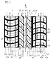
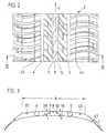
- Figures 1 to 3 show a direction of rotation independent of the invention Tread pattern of a pneumatic vehicle tire with shoulder girth straps 1 and 2, each from one behind the other in the circumferential direction identical profile block elements 31 and 41 are constructed and separated from one another by transverse grooves 34 and 44, respectively are.
- Between the shoulder circumferential bands 1 and 2 is through wide circumferential grooves 4 and 5 from the shoulder circumferential bands 1 and 2 separate the central peripheral region 3, consisting of 2 central circumferential bands 6 and 7 each with the circumference distributed block elements 21 and 11 arranged, the adjacent profile block elements 21 and the adjacent profile block elements 11 from each other are separated from one another by a transverse groove 24 or 14.
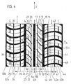
- the axial width B of the central region 3 is 40 to 50% of the axial contact width A, but is chosen at least so large that it is wider than the distance the longitudinal grooves of water drainage in streets 1 inch (i.e. wider than 25.4 mm).
- the central circumferential rib 8 is parallel to the circumference of the tire arranged with inclined sipes 17 constant slope in the circumferential direction over the left to right axis direction including a Gradient angle ⁇ formed.
- the transverse grooves 14 and 24 of the central circumferential bands 6 and 7 run with negative Incline in the circumferential direction above that from left to right current axis direction 9 at an angle ⁇ to Axis direction.
- ⁇ takes values between 50 ° and 70 °, preferably 60 °.
- the wide circumferential grooves 4 and 5 with the narrow Circumferential grooves 9 and 10 connecting transverse grooves 14 and 24 respectively central circumferential bands 6 and 7 run in their groove depth initially essentially at the depth of the groove depth wide circumferential grooves 4 and 5.
- Immediately following the Half of its axial extension begins at the bottom of the groove increase axially on the inside until it transitions into the narrow circumferential grooves 9 and 10 a depth of 50% of Depth of the wide circumferential grooves 4 and 5 has reached.
- Profile block elements 11 and 21 are thereby in this particularly sensitive area due to the pointed course Vibration uneven abrasion and saw tooth formation on the central circumferential groove 8 tied and stiffened.
- the slats 16 and 26 are, as in the illustrations, not can be seen in their adjacent circumferential grooves 4, 5, 9, 10 indicate the end areas in their incision depth continuously decreasing so that the partial profile block elements 12, 13 or 22 or 23 of each profile block element 11 and 21 in their axial edge area to the adjacent circumferential grooves stiffening towards each other are connected and still form traction edges.
- Ventilation of the transverse fins 26 and 16 is in the axial Center area of a partial profile block element 13 or 23 of a profile block element in the circumferential direction running, narrow ventilation grooves 15 and 25 formed, whose width is 88% of the width of the narrow circumferential grooves 3 or 9.
- vent grooves 15 and 25 of the two central circumferential bands 6 and 7 are mirror images Arrangement to the dividing the profile block elements Transverse lamella 16 or 26 formed, i.e. in the central Circumferential band 7 is the ventilation groove 15 in the circumferential direction the associated transverse lamella 16 each downstream and in Circumferential band 6 is the ventilation groove of the associated Transverse lamella 26 upstream in the circumferential direction educated.
- the transverse grooves 34 and 44 of the shoulder circumferential rows 1 and 2 extend in the axial direction from the adjacent wide circumferential groove 4 and 5 axially outward over the entire shoulder area to the shoulder decor area c out and run under one Pitch angle ⁇ to the axial direction a, that in the axial End of shoulder circumference rows 1 and 2 to adjacent wide circumferential grooves 4 and 5 a maximum of 15 to 25 °, preferably 20 ° and under continuous Decrease of the slope in the circumferential direction over the axial direction decreases continuously axially towards the decor area, whereby the slope of the transverse groove 36 to 46 and thus the angle ⁇ in the axial edge area of the contact width A essentially Is 0 ° and more continuously more continuously Decrease the slope up to the decorative area c the angle ⁇ as a measure of the slope of the transverse groove 44 or 34 in Circumferential direction over the axis direction even negative values accepts.
- the axial contact area A is one over the circumference of the Pneumatic tire extending circumferential groove 47 for Decoupling the shoulder decor area c from the rest Shoulder area trained.
- the profile block elements 31 and 41 of the shoulder circumferential bands 1 or 2 are each by one or two each profile block element 31 or 41 in two or three sub-block elements 32 a, b, c and 42 a, b, c divided so that the Sub-block elements of each profile block element in each case have the same circumferential lengths.
- the transverse slats 36 and 46 extend from the wide circumferential grooves 4 and 5 over the entire contact area A to the outside via the decoupling groove 47 into the decorative area c and are parallel to the transverse grooves 34 and 44 of the respective shoulder circumferential band 1 or 2 formed.
- Vents 39 and 49 respectively formed in the circumferential direction, each having a transverse groove 44 or 43 with the transverse slats 45 or 35 of a profile block element 31 or 41 connects.
- the ventilation grooves in the shoulder circumference band 1 are the ventilation grooves in the circumferential direction of the cross blades downstream and in the circumferential band 2 are the ventilation grooves 49 upstream of the associated transverse slats 46 educated.
- the location of these ventilation grooves is therefore each opposite the ventilation grooves 25 and 15 of the adjacent central circumferential band 6 and 7 compared to transverse slats 16 and 26 formed there are inverted.
- the ventilation grooves 35 or 45 narrower or the same width as the narrow ones Circumferential grooves 9 and 10 and with a maximum depth of 50% the depth of the wide circumferential grooves 4, 5 formed.
- the Decoupling groove 47 is 50% deep of the ventilation grooves 35 and with a width that the width corresponds to the ventilation grooves.
- the bottom of the groove begins Cross grooves 14 and 24 in the depth of the transition of Radius of curvature R of the curvature of the wide circumferential groove 4 or 5 in the sloping side wall of the wide circumferential groove 4 or 5.
- the narrow ones Circumferential grooves 9 and 10 retain the transverse grooves 18 and 28, respectively this depth over a width of 80 to 85% of the axial Width of the central circumferential bands 6 and 7 at only in the last 15 to 20% of the axial width of the central one Circumferential bands 6 and 7 increase continuously, so that they in the central transition area to the narrow circumferential grooves 9 or 10 have a depth t that the depth of the narrow Corresponds circumferential groove 9 or 10.
- the Ventilation groove 15 or 25 with 90% of the width of the narrow Circumferential grooves 9 and 10 are formed.
- the narrow circumferential groove 9 or 10 is with a width of 50% of the ventilation and Decoupling grooves 45 and 47 formed.
- the narrow circumferential grooves 9 and 10 of both embodiments 1 and 4 are of a width of 10 to 40% of the width of the wide circumferential grooves 4, 5, 7 educated.
- the width of the wide circumferential grooves 4, 5 is 5 to 6%, for example 5, 7% of the width of the contact patch Contour tread width in the unloaded state.
- the Shoulder profile block elements 41 and 31 to the neighboring ones Profile block elements 11 and 21 of the central circumferential bands 6 and 7 seen in the circumferential direction for noise reduction staggered.
- the profile block elements 11 are also and 21 of the central circumferential bands 6 and 7 to each other in Staggered circumferential direction.
Landscapes
- Engineering & Computer Science (AREA)
- Mechanical Engineering (AREA)
- Tires In General (AREA)
Claims (11)
- Profil de bande de roulement non lié au sens de rotation d'un pneu de véhicule à structure de profil contenant des blocs, comprenant :caractérisédeux bandes circonférentielles centrales (6, 7) d'éléments-blocs de profils (11, 21) disposés en étant répartis l'un derrière l'autre sur la circonférence et une nervure circonférentielle centrale (8) séparée de ces bandes circonférentielles (6, 7) par des rainures circonférentielle étroites (9, 10), disposée en étant adjacente entre ces bandes circonférentielles,deux bandes circonférentielles d'épaulement (1, 2) comprenant des éléments-blocs de profil (31, 41) disposés en étant répartis sur la circonférence, éléments-blocs de profil dont un élément est disposé à chaque fois en étant adjacent à l'une des deux bandes circonférentielles centrales (6, 7) et séparé de cette bande circonférentielle centrale par une rainure circonférentielle large (4, 5),où les éléments-blocs de profil (11, 21, 31, 41) de toutes les bandes circonférentielles (6, 7, 1, 2) sont à chaque fois séparés des éléments-blocs de profil adjacents de la même bande circonférentielle par une rainure transversale (14, 24, 34, 44) s'étendant sur toute la largeur de la bande circonférentielle respective, où ces rainures transversales (14, 24, 34, 44) à l'intérieur d'une bande circonférentielle s'étendent dans la direction circonférentielle en ayant une pente constante et en étant à chaque fois parallèles entre elles dans la direction axiale, où la composante, en direction circonférentielle, des rainures transversales (14, 24) des bandes circonférentielles centrales (6, 7) ne subit aucun point d'inflexion et, dans la zone des rainures circonférentielles larges de séparation (4, 5), l'allure de la pente des rainures transversales adjacentes axialement (14, 44 ; 24, 34) est inversée par une modification de direction non constante de la composante circonférentielle,en ce que le fond de la rainure circonférentielle étroite (9, 10) est configuré en étant maximal dans la profondeur du fond de la rainure circonférentielle large (4, 5), sur toute l'étendue circonférentielle de la rainure circonférentielle étroite,où les rainures transversales (14, 24) des bandes circonférentielles centrales (6, 7), dans la zone d'extrémité axiale des rainures transversales (14, 24), tournée vers la rainure circonférentielle étroite (9, 10), zone d'extrémité qui est au maximum à 50 %, notamment entre 15 % et 35 % de l'étendue axiale de la rainure transversale (14, 24), partent dans leur allure en profondeur, d'une profondeur qui correspond à la profondeur des rainures circonférentielles larges (4, 5), et montent en continu en direction de la rainure circonférentielle étroite (9).
- Profil de bande de roulement non lié au sens de rotation selon les mentions de la revendication 1,où une rainure circonférentielle (37 ; 47) découplant un des éléments-blocs de profil (31, 41) de la bande circonférentielle d'épaulement (1, 2) est configurée axialement à l'extérieur de la surface de contact (A), dans au moins une des deux bandes circonférentielles d'épaulement (1, 2).
- Profil de bande roulement non lié au sens de rotation selon les mentions de la revendication 1, comprenant :une partie négative de la surface sur la totalité de la surface dans la zone médiane centrale (B) formée entre les rainures circonférentielles larges (4, 5), variant entre 10 % et 15 % et variant notamment entre 16 % et 20 % dans la bande circonférentielle d'épaulement.
- Profil de bande de roulement non lié au sens de rotation selon les mentions de la revendication 3,où la nervure circonférentielle centrale (8) est divisée en deux nervures circonférentielles (8a, 8b) par une autre rainure circonférentielle (48) large et centrale, où la largeur de cette rainure circonférentielle (48), correspond en particulier pratiquement à la largeur des rainures circonférentielles larges (4, 5) disposées entre les bandes circonférentielles centrales (6, 7) et les bandes d'épaulement (1, 2), lesquelles rainures circonférentielles sont formées en ayant de préférence une largeur comprise entre 10 % et 20 % de la largeur de la zone centrale (B), où la largeur des rainures circonférentielles étroites (9, 10) est constituée de préférence de 10 % à 20 %, en particulier de 14 % des rainures circonférentielles larges (4, 5).
- Profil de bande de roulement non lié au sens de rotation selon les mentions de la revendication 1,où la nervure circonférentielle centrale (8) comprenant des lamelles obliques parallèles (17), notamment de pente constante, est configurée en ayant une allure de pente opposée à celle des rainures transversales formées (14, 24) dans les deux bandes circonférentielles centrales adjacentes (6, 7).
- Profil de bande de roulement non lié au sens de rotation selon les mentions de la revendication 1,où, parallèlement aux rainures transversales (14, 24) des bandes circonférentielles centrales (6, 7), dans les éléments-blocs de profil (11, 21) de ces bandes circonférentielles (6, 7), une lamelle transversale divisant l'élément-bloc de profil (11, 21) en deux parties (22, 23 ; 12, 13) de même longueur circonférentielle est configurée en s'étendant à chaque fois sur la largeur axiale de la bande circonférentielle centrale respective (6, 7).
- Profil de bande de roulement non lié au sens de rotation selon les mentions de la revendication 6, comprenant :dans respectivement une (13, 23) des deux parties (13, 12 ; 23, 22) de l'élément-bloc de profil (11, 21), une rainure d'évacuation (14, 25) reliant la rainure transversale (14, 24) contiguë à cette partie et la lamelle transversale (16, 26), la rainure d'évacuation étant formée pratiquement dans la direction circonférentielle.
- Profil de bande de roulement non lié au sens de rotation selon les mentions de la revendication 1, comprenant :des lamelles transversales (36, 46) divisant les différents éléments-blocs de profil d'épaulement (31, 41) à chaque fois en parties de même longueur circonférentielle, s'étendant pratiquement sur toute la largeur de la bande d'épaulement (1, 2) jusque dans la zone de décoration, configurées parallèlement à la rainure transversale (34, 44) au moins d'une bande d'épaulement (1, 2).
- Profil de bande de roulement non lié au sens de rotation selon les mentions de la revendication 8, comprenant :une rainure d'évacuation (35, 45) configurée comme une rainure circonférentielle dans la bande circonférentielle d'épaulement (1, 2) dans la zone axiale de la surface de contact (A).
- Profil de bande de roulement non lié au sens de rotation selon les mentions de l'une ou de plusieurs des revendications 1 à 9,où les rainures transversales (34, 44) de la bande circonférentielle d'épaulement (1, 2), dans la zone latérale axiale de la surface de contact (A), s'étendent pratiquement de façon parallèle à la direction axiale.
- Profil de bande de roulement non lié au sens de rotation selon les mentions de la revendication 1,où le fond de la rainure de la rainure circonférentielle large (4, 5) est configuré, en coupe transversale, en ayant une zone recourbée,où le fond de la rainure circonférentielle étroite (9, 10) est configuré au maximum avec la profondeur de la zone recourbée du fond de la rainure circonférentielle large (4, 5), sur la totalité de la circonférence de la rainure circonférentielle étroite (9, 10).
Priority Applications (3)
| Application Number | Priority Date | Filing Date | Title |
|---|---|---|---|
| DE59510335T DE59510335D1 (de) | 1995-11-09 | 1995-11-09 | Drehrichtungsungebundenes Laufstreifenprofil eines Fahrzeugreifens mit Blockprofilstruktur |
| AT95117679T ATE222545T1 (de) | 1995-11-09 | 1995-11-09 | Drehrichtungsungebundenes laufstreifenprofil eines fahrzeugreifens mit blockprofilstruktur |
| EP95117679A EP0773117B1 (fr) | 1995-11-09 | 1995-11-09 | Profil de bande de roulement non-directionnel pour un bandage pneumatique avec une structure de profil contenant des blocs |
Applications Claiming Priority (1)
| Application Number | Priority Date | Filing Date | Title |
|---|---|---|---|
| EP95117679A EP0773117B1 (fr) | 1995-11-09 | 1995-11-09 | Profil de bande de roulement non-directionnel pour un bandage pneumatique avec une structure de profil contenant des blocs |
Publications (2)
| Publication Number | Publication Date |
|---|---|
| EP0773117A1 EP0773117A1 (fr) | 1997-05-14 |
| EP0773117B1 true EP0773117B1 (fr) | 2002-08-21 |
Family
ID=8219798
Family Applications (1)
| Application Number | Title | Priority Date | Filing Date |
|---|---|---|---|
| EP95117679A Expired - Lifetime EP0773117B1 (fr) | 1995-11-09 | 1995-11-09 | Profil de bande de roulement non-directionnel pour un bandage pneumatique avec une structure de profil contenant des blocs |
Country Status (3)
| Country | Link |
|---|---|
| EP (1) | EP0773117B1 (fr) |
| AT (1) | ATE222545T1 (fr) |
| DE (1) | DE59510335D1 (fr) |
Families Citing this family (12)
| Publication number | Priority date | Publication date | Assignee | Title |
|---|---|---|---|---|
| JP3515232B2 (ja) * | 1995-07-11 | 2004-04-05 | 横浜ゴム株式会社 | 空気入りタイヤ及びその使用方法 |
| JP3335118B2 (ja) * | 1998-01-19 | 2002-10-15 | 住友ゴム工業株式会社 | 重荷重用タイヤ |
| DE69930481T2 (de) * | 1998-10-30 | 2006-10-19 | Sumitomo Rubber Industries Ltd., Kobe | Fahrzeugreifen |
| ES2323007T3 (es) * | 2000-01-26 | 2009-07-03 | Bridgestone Corporation | Neumatico. |
| US6450223B1 (en) * | 2000-05-23 | 2002-09-17 | The Goodyear Tire & Rubber Company | Pneumatic tire having improved wet traction |
| JP4156018B1 (ja) * | 2007-12-12 | 2008-09-24 | 横浜ゴム株式会社 | 空気入りタイヤ |
| JP4685919B2 (ja) * | 2008-12-08 | 2011-05-18 | 住友ゴム工業株式会社 | 空気入りタイヤ |
| WO2010133940A1 (fr) * | 2009-05-19 | 2010-11-25 | Pirelli Tyre S.P.A. | Pneu pour véhicule à moteur |
| JP5632823B2 (ja) * | 2011-12-26 | 2014-11-26 | 住友ゴム工業株式会社 | 重荷重用空気入りタイヤ |
| US10252577B2 (en) | 2012-11-15 | 2019-04-09 | The Yokohama Rubber Co., Ltd. | Pneumatic tire |
| CA2877642C (fr) * | 2012-11-15 | 2017-03-21 | The Yokohama Rubber Co., Ltd. | Pneumatique |
| CN108189624A (zh) * | 2018-02-09 | 2018-06-22 | 建大橡胶(中国)有限公司 | 一种运动型花纹轮胎 |
Family Cites Families (6)
| Publication number | Priority date | Publication date | Assignee | Title |
|---|---|---|---|---|
| DE8628836U1 (de) * | 1986-10-29 | 1988-02-25 | Uniroyal Englebert Reifen GmbH, 5100 Aachen | Fahrzeugluftreifen |
| AT390913B (de) * | 1988-01-27 | 1990-07-25 | Semperit Ag | Laufflaechenprofil fuer einen fahrzeugluftreifen |
| DE9016455U1 (de) * | 1990-12-04 | 1991-07-25 | Uniroyal Englebert Reifen GmbH, 5100 Aachen | Fahrzeugluftreifen |
| DE4107051A1 (de) * | 1991-03-06 | 1992-09-10 | Uniroyal Englebert Gmbh | Fahrzeugluftreifen |
| AT400135B (de) * | 1991-12-12 | 1995-10-25 | Semperit Ag | Fahrzeugreifen |
| JP3160154B2 (ja) * | 1993-07-23 | 2001-04-23 | 住友ゴム工業株式会社 | 左側通行用空気入りタイヤ |
-
1995
- 1995-11-09 EP EP95117679A patent/EP0773117B1/fr not_active Expired - Lifetime
- 1995-11-09 DE DE59510335T patent/DE59510335D1/de not_active Expired - Lifetime
- 1995-11-09 AT AT95117679T patent/ATE222545T1/de not_active IP Right Cessation
Also Published As
| Publication number | Publication date |
|---|---|
| EP0773117A1 (fr) | 1997-05-14 |
| ATE222545T1 (de) | 2002-09-15 |
| DE59510335D1 (de) | 2002-09-26 |
Similar Documents
| Publication | Publication Date | Title |
|---|---|---|
| DE19753819B4 (de) | Laufflächenprofil eines Winterreifens | |
| EP3589500B1 (fr) | Pneumatique de véhicule | |
| DE602004002526T2 (de) | Reifenlauffläche | |
| EP3589501A1 (fr) | Pneumatique de véhicule | |
| WO2009077231A1 (fr) | Pneumatique de véhicule | |
| DE102015224288A1 (de) | Fahrzeugluftreifen | |
| EP3300926B1 (fr) | Pneumatiques de véhicule | |
| EP0773117B1 (fr) | Profil de bande de roulement non-directionnel pour un bandage pneumatique avec une structure de profil contenant des blocs | |
| EP3421264B1 (fr) | Pneumatique de véhicule | |
| WO2018033268A1 (fr) | Pneumatique de véhicule | |
| EP2900489B1 (fr) | Pneumatique pour véhicule | |
| EP2138327B1 (fr) | Bande de roulement pour pneumatique | |
| EP2138329B1 (fr) | Bande de roulement pour pneumatique | |
| EP0112533B1 (fr) | Profil de surface de roulement pour bandage pneumatique pour neige et boue | |
| EP3300925B1 (fr) | Pneumatiques de véhicule | |
| EP4244079B1 (fr) | Pneumatique de véhicule | |
| EP2138328B1 (fr) | Pneus de véhicule | |
| EP3663105B1 (fr) | Pneu de véhicule | |
| EP3888951B1 (fr) | Pneumatique de véhicule | |
| EP4173847A1 (fr) | Bandage pneumatique pour véhicule | |
| EP3686033B1 (fr) | Pneumatiques de véhicule | |
| EP2000329A1 (fr) | Bandages pneumatiques | |
| EP1535759B1 (fr) | Bandage pneumatique | |
| EP3277524B1 (fr) | Pneumatique | |
| EP4166355B1 (fr) | Bandage pneumatique pour véhicule |
Legal Events
| Date | Code | Title | Description |
|---|---|---|---|
| PUAI | Public reference made under article 153(3) epc to a published international application that has entered the european phase |
Free format text: ORIGINAL CODE: 0009012 |
|
| AK | Designated contracting states |
Kind code of ref document: A1 Designated state(s): AT BE CH DE DK ES FR GB GR IE IT LI LU NL PT SE |
|
| 17P | Request for examination filed |
Effective date: 19971114 |
|
| 17Q | First examination report despatched |
Effective date: 19990722 |
|
| GRAG | Despatch of communication of intention to grant |
Free format text: ORIGINAL CODE: EPIDOS AGRA |
|
| 18R | Application refused |
Effective date: 20010127 |
|
| GRAG | Despatch of communication of intention to grant |
Free format text: ORIGINAL CODE: EPIDOS AGRA |
|
| GRAH | Despatch of communication of intention to grant a patent |
Free format text: ORIGINAL CODE: EPIDOS IGRA |
|
| GRAH | Despatch of communication of intention to grant a patent |
Free format text: ORIGINAL CODE: EPIDOS IGRA |
|
| 18RA | Request filed for re-establishment of rights before grant |
Effective date: 20010627 |
|
| 18RR | Decision to grant the request for re-establishment of rights before grant |
Free format text: 20011105 ANGENOMMEN |
|
| GRAH | Despatch of communication of intention to grant a patent |
Free format text: ORIGINAL CODE: EPIDOS IGRA |
|
| GRAA | (expected) grant |
Free format text: ORIGINAL CODE: 0009210 |
|
| AK | Designated contracting states |
Kind code of ref document: B1 Designated state(s): AT BE CH DE DK ES FR GB GR IE IT LI LU NL PT SE |
|
| PG25 | Lapsed in a contracting state [announced via postgrant information from national office to epo] |
Ref country code: NL Free format text: LAPSE BECAUSE OF FAILURE TO SUBMIT A TRANSLATION OF THE DESCRIPTION OR TO PAY THE FEE WITHIN THE PRESCRIBED TIME-LIMIT Effective date: 20020821 Ref country code: IE Free format text: LAPSE BECAUSE OF FAILURE TO SUBMIT A TRANSLATION OF THE DESCRIPTION OR TO PAY THE FEE WITHIN THE PRESCRIBED TIME-LIMIT Effective date: 20020821 Ref country code: GR Free format text: LAPSE BECAUSE OF FAILURE TO SUBMIT A TRANSLATION OF THE DESCRIPTION OR TO PAY THE FEE WITHIN THE PRESCRIBED TIME-LIMIT Effective date: 20020821 |
|
| REF | Corresponds to: |
Ref document number: 222545 Country of ref document: AT Date of ref document: 20020915 Kind code of ref document: T |
|
| REG | Reference to a national code |
Ref country code: CH Ref legal event code: EP |
|
| REF | Corresponds to: |
Ref document number: 59510335 Country of ref document: DE Date of ref document: 20020926 |
|
| REG | Reference to a national code |
Ref country code: IE Ref legal event code: FG4D Free format text: GERMAN |
|
| PG25 | Lapsed in a contracting state [announced via postgrant information from national office to epo] |
Ref country code: LU Free format text: LAPSE BECAUSE OF NON-PAYMENT OF DUE FEES Effective date: 20021109 Ref country code: AT Free format text: LAPSE BECAUSE OF NON-PAYMENT OF DUE FEES Effective date: 20021109 |
|
| PG25 | Lapsed in a contracting state [announced via postgrant information from national office to epo] |
Ref country code: SE Free format text: LAPSE BECAUSE OF FAILURE TO SUBMIT A TRANSLATION OF THE DESCRIPTION OR TO PAY THE FEE WITHIN THE PRESCRIBED TIME-LIMIT Effective date: 20021121 Ref country code: DK Free format text: LAPSE BECAUSE OF FAILURE TO SUBMIT A TRANSLATION OF THE DESCRIPTION OR TO PAY THE FEE WITHIN THE PRESCRIBED TIME-LIMIT Effective date: 20021121 |
|
| PG25 | Lapsed in a contracting state [announced via postgrant information from national office to epo] |
Ref country code: LI Free format text: LAPSE BECAUSE OF NON-PAYMENT OF DUE FEES Effective date: 20021130 Ref country code: CH Free format text: LAPSE BECAUSE OF NON-PAYMENT OF DUE FEES Effective date: 20021130 Ref country code: BE Free format text: LAPSE BECAUSE OF NON-PAYMENT OF DUE FEES Effective date: 20021130 |
|
| PG25 | Lapsed in a contracting state [announced via postgrant information from national office to epo] |
Ref country code: PT Free format text: LAPSE BECAUSE OF FAILURE TO SUBMIT A TRANSLATION OF THE DESCRIPTION OR TO PAY THE FEE WITHIN THE PRESCRIBED TIME-LIMIT Effective date: 20021204 |
|
| NLV1 | Nl: lapsed or annulled due to failure to fulfill the requirements of art. 29p and 29m of the patents act | ||
| ET | Fr: translation filed | ||
| GBT | Gb: translation of ep patent filed (gb section 77(6)(a)/1977) |
Effective date: 20030213 |
|
| BERE | Be: lapsed |
Owner name: *UNIROYAL ENGLEBERT REIFEN G.M.B.H. Effective date: 20021130 |
|
| PLBE | No opposition filed within time limit |
Free format text: ORIGINAL CODE: 0009261 |
|
| STAA | Information on the status of an ep patent application or granted ep patent |
Free format text: STATUS: NO OPPOSITION FILED WITHIN TIME LIMIT |
|
| REG | Reference to a national code |
Ref country code: CH Ref legal event code: PL |
|
| REG | Reference to a national code |
Ref country code: IE Ref legal event code: FD4D Ref document number: 0773117E Country of ref document: IE |
|
| 26N | No opposition filed |
Effective date: 20030522 |
|
| PGFP | Annual fee paid to national office [announced via postgrant information from national office to epo] |
Ref country code: GB Payment date: 20041102 Year of fee payment: 10 |
|
| PGFP | Annual fee paid to national office [announced via postgrant information from national office to epo] |
Ref country code: FR Payment date: 20041112 Year of fee payment: 10 |
|
| PG25 | Lapsed in a contracting state [announced via postgrant information from national office to epo] |
Ref country code: IT Free format text: LAPSE BECAUSE OF NON-PAYMENT OF DUE FEES Effective date: 20051109 Ref country code: GB Free format text: LAPSE BECAUSE OF NON-PAYMENT OF DUE FEES Effective date: 20051109 |
|
| GBPC | Gb: european patent ceased through non-payment of renewal fee |
Effective date: 20051109 |
|
| PG25 | Lapsed in a contracting state [announced via postgrant information from national office to epo] |
Ref country code: FR Free format text: LAPSE BECAUSE OF NON-PAYMENT OF DUE FEES Effective date: 20060731 |
|
| REG | Reference to a national code |
Ref country code: FR Ref legal event code: ST Effective date: 20060731 |
|
| PG25 | Lapsed in a contracting state [announced via postgrant information from national office to epo] |
Ref country code: ES Free format text: LAPSE BECAUSE OF NON-PAYMENT OF DUE FEES Effective date: 20021130 |
|
| PGFP | Annual fee paid to national office [announced via postgrant information from national office to epo] |
Ref country code: DE Payment date: 20101202 Year of fee payment: 16 |
|
| PG25 | Lapsed in a contracting state [announced via postgrant information from national office to epo] |
Ref country code: DE Free format text: LAPSE BECAUSE OF THE APPLICANT RENOUNCES Effective date: 20110120 |
|
| REG | Reference to a national code |
Ref country code: DE Ref legal event code: R081 Ref document number: 59510335 Country of ref document: DE Owner name: CONTINENTAL REIFEN DEUTSCHLAND GMBH, DE Free format text: FORMER OWNER: UNIROYAL ENGLEBERT REIFEN GMBH, 52068 AACHEN, DE Effective date: 20110405 |