EP0773177A2 - Vakuum-Förderer - Google Patents
Vakuum-Förderer Download PDFInfo
- Publication number
- EP0773177A2 EP0773177A2 EP96301851A EP96301851A EP0773177A2 EP 0773177 A2 EP0773177 A2 EP 0773177A2 EP 96301851 A EP96301851 A EP 96301851A EP 96301851 A EP96301851 A EP 96301851A EP 0773177 A2 EP0773177 A2 EP 0773177A2
- Authority
- EP
- European Patent Office
- Prior art keywords
- vacuum
- elongated
- belt
- support means
- belt support
- Prior art date
- Legal status (The legal status is an assumption and is not a legal conclusion. Google has not performed a legal analysis and makes no representation as to the accuracy of the status listed.)
- Withdrawn
Links
Images



Classifications
-
- B—PERFORMING OPERATIONS; TRANSPORTING
- B65—CONVEYING; PACKING; STORING; HANDLING THIN OR FILAMENTARY MATERIAL
- B65H—HANDLING THIN OR FILAMENTARY MATERIAL, e.g. SHEETS, WEBS, CABLES
- B65H5/00—Feeding articles separated from piles; Feeding articles to machines
- B65H5/22—Feeding articles separated from piles; Feeding articles to machines by air-blast or suction device
- B65H5/222—Feeding articles separated from piles; Feeding articles to machines by air-blast or suction device by suction devices
- B65H5/224—Feeding articles separated from piles; Feeding articles to machines by air-blast or suction device by suction devices by suction belts
-
- B—PERFORMING OPERATIONS; TRANSPORTING
- B65—CONVEYING; PACKING; STORING; HANDLING THIN OR FILAMENTARY MATERIAL
- B65H—HANDLING THIN OR FILAMENTARY MATERIAL, e.g. SHEETS, WEBS, CABLES
- B65H2406/00—Means using fluid
- B65H2406/30—Suction means
- B65H2406/32—Suction belts
- B65H2406/322—Suction distributing means
- B65H2406/3223—Suction distributing means details of the openings in the belt, e.g. shape, distribution
Definitions
- This invention relates to a conveyor for moving an object having a relatively planar bottom surface by means of an apertured belt communicating with a vacuum chamber.
- the objects transported may be as diverse as a container having a planar bottom surface, a bundle of sheets or single sheet material having a relatively rigid bottom surface.
- this application will primarily be directed to the transport of laminated, solid fiber and corrugated paper sheets used in making boxes and inserts.
- the corrugated sheets may be rectangles with even edges or die cut with slits and flaps.
- conveyors used in transporting flat corrugated box blanks such as Martin 3,658,322 (1972) have required a plurality of upper and lower flat conveyor belts which required synchronous speed mechanisms and spacing mechanisms to keep the blanks moving uniformly and in a straight line.
- the mechanisms needed to operate reliably for long periods of time were relatively costly to manufacture, set up and maintain.
- Snubbers sometimes can be used to hold sheets to conveyors, as used in Martin U.S. 4,099,712 granted in 1973. Snubbers may be used efficiently with sheet material, but are not suitable for boxes or packages.
- Pinch rollers as disclosed in Martin 4,183,271 granted in 1980 have been used very effectively in carrying webs of corrugated sheet material to rotary shear machines, but pinch rollers compress the corrugated sheet material in order to maintain an adequate grip on the material.
- the sheet material has been made of recycled fibers which are shorter and more subject to compression and it has been difficult to avoid overcompression of the corrugated sheet material with pinch rollers.
- U.S. 4,805,890 granted to Martin in 1980 discloses the use of suction openings placed between flat non-perforated conveyor belts. While this system holds the sheet material to the conveyor quite well, the orifices 16A as shown in FIG. 6 tend to act like stationary suction cups acting against the bottom of the sheet material; preventing longitudinal movement. Such a system requires the input of additional energy into the belt system to overcome the vacuum acting on the sheet material.
- the gist of the present invention is a structure which results in maximum vacuum applied through the perforations in the conveyor belt to the object being conveyed with a minimum vacuum applied to the non-perforated portions of the conveyor belt thus reducing drag on the belts.
- a vacuum restrictor is used to reduce the effective opening in the slot between the belt supporting means such as rails at selected points along the longitudinal axis of the rails thereby varying the suction force on the object being conveyed.
- additional belt supporting means such as an additional rail or rails are provided which provide additional support to the belt.
- the support system is provided with ports to dump the vacuum to atmosphere to reduce the drag on the belt.
- An object of the present invention is to maximize the suction force on the object being transported while reducing the frictional drag on the belt.
- Another object is to provide a conveyor which varies the suction force on the transported object along the longitudinal axis of the conveyor.
- Still another object is to minimize the tendency of the sheets being transported to skew while being conveyed.
- a further object is to minimize slippage between the belt and the sheet being transported; particularly at the upstream end of the conveyor where the article being transported is initially accelerated rapidly.
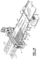
- FIG. 1 is a perspective view of one form of the invention used in conjunction with a slitter and rotary cutoff knife illustrated in FIG. 1A.
- FIG. 1A is a perspective view of a typical slitter and prior art cutoff knife installation using pinch rollers instead of the vacuum conveyor of the present invention.
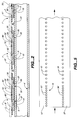
- Fig 2 is a cross sectional view of a portion of the conveyor of one form of the present invention taken along line 2-2 of FIG. 1.
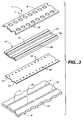
- FIG. 3 is an exploded perspective view of a portion of the vacuum conveyor of another form of the present invention similar to the portion of the conveyor shown in FIG. 4.
- FIG. 4 is a top plan view of a portion of the conveyor of another form of the present invention with the endless belt removed for purposes of clarity. For informational purposes, Fig 4 is taken along line 4-4 in FIG 4A. FIG 4 is a modified form of a portion of the conveyor illustrated in FIG. 2.
- FIG. 4A is a sectional view of a portion of the conveyor of the present invention taken along line 4A- 4A in FIG. 4.
- FIG 4B is still another form of the invention similar to the invention illustrated in FIG. 4A and taken along line 4A - 4A in FIG. 4.
- FIG. 5 is a top plan view of a portion of another form of vacuum regulator illustrated in FIG. 4A.
- FIG. 6A is a top plan view of another form of vacuum conveyor.
- FIG. 6B is a cross sectional view of the vacuum conveyor illustrated in FIG. 6A.
- FIG. 6C is a top plan view of the form of vacuum conveyor illustrated in FIG. 6A in conjunction with another form of vacuum belt.
- FIG. 6D is a cross sectional view of the vacuum conveyor illustrated in FIG. 6C taken along line 6D - 6D.
- FIG. 7A is a top plan view of another form of vacuum conveyor of the present invention.
- FIG. 7B is a partial cross sectional view of the vacuum conveyor illustrated in FIG. 7A taken along line 7B - 7B with a cross sectional view of a corrugated sheet.
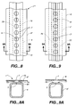
- FIG. 8 is a top plan view of still another form of the invention.
- FIG. 8A is a cross sectional view taken along line 8A-8A in FIG. 8.
- FIG. 9 is a top plan view of another form of the invention.
- FIG. 9A is a cross sectional view taken along line 9A-9A in FIG. 9.
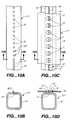
- FIG. 10A is a top plan view of yet another form of vacuum conveyor of the present invention.
- FIG. 10B is a cross sectional view of the conveyor in FIG. 10A taken along line 10B-10B.
- FIG. 10C is a top plan view of another form of the invention.
- FIG. 10D is a cross sectional view of the invention illustrated in FIG. 10C and taken along line 10D - 10D.
- the vacuum conveyor 1 for moving an object 2 having at least one relatively planar surface 3, and the planar surface 3 of the object 2 having a substantial area relatively imperforate to vacuum transmission, and formed from a material having a selected stiffness resisting selected bending consists of: an elongated vacuum chamber 4 having first opening means 5; an elongated endless belt 6 having a plurality of first perforated openings 7 positioned for vacuum communication with the first opening means 5 in the vacuum chamber 4, having a stiffness capable of maintaining a portion of the area of the endless belt 6 in a generally planar position; a laterally and longitudinally extending first belt support means 8 having an effective width less than the width of the endless belt and having first belt support opening means 9 in vacuum communication with the vacuum chamber 4 and extending over a substantial elongated portion 17 of the endless belt 6; vacuum generating means 10 similar to the generating means illustrated in FIG. 1 providing a suction in the vacuum chamber 4; and belt drive means
- the upper side of the vacuum chamber 4 forming the first belt support means 8 may be formed as a raised land portion which has a width less than the width of the endless belt 6.
- first belt support opening means 9 and first opening means 5 have a common size area of opening, but this may vary with the design requirements.
- first belt support openings means 9 and first opening means 5 consist of a series of elongated openings forming a generally straight line.
- Other designs may consist of an elongated slot or series of slots or the openings may have any geometric shape such as circles, rectangles or obround openings.
- a feature of the present vacuum conveyor 1 is the ability to vary the force with which the objects being conveyed are held to the endless belt 6. This is especially important where the vacuum conveyor must accelerate the object being conveyed from a rest or slower velocity to a higher velocity.
- the use of greater vacuum force reduces the amount of slippage between the belt 6 and the object 2 so that rapid acceleration will be achieved.
- the conveyor may be provided with vacuum force varying means 16 varying the vacuum applied to the planar surface 3 of the object 2 as a function of the linear distance along the elongated endless belt 6.
- This may be achieved by varying the area of the first opening means 9 in the first belt support means 8 of the vacuum force varying means 16.
- Variance in the area of the first belt support opening means 9 may also be achieved by simply placing the openings closer together. (See the spacing variance of the openings 15' and 15'' in FIG. 5).
- Another way of achieving variance in the vacuum force varying means 16 is to simply increase the width of the slot in the first opening means 5 and first belt support opening means 9.
- FIGS. 7A and 7B Another form of vacuum conveyor 1' is illustrated in FIGS. 7A and 7B in which the first belt support means 8' includes a pair of laterally spaced elongated rails 12 and 13 defining the first belt support opening means 9'.
- the purpose of the rails is to provide a convenient means of elevating the endless belt 6 above the vacuum chamber 4.
- the width of the rails 12 and 13 should be designed so that they are less than the width of the endless belt 6 yet will maintain the belt 6 in a relatively planar position.
- the height of the rails 12 and 13 should be such that contact between the belt 6 and the vacuum chamber 4 will be minimized.
- the opening means 5 in the elongated vacuum chamber 4 is a slot which is wider than the first belt support opening means 9' between the rails 12 and 13; and the transverse width of a substantial portion of the first perforated openings 7 in the elongated endless belt 6 is greater than the width of the first belt support opening means 9' between the rails 12 and 13.
- Use of the word "slot" in the above context may mean a series of first belt support openings 9 as illustrated in FIG. 6A; thus forming a slot-like opening.
- the purpose of providing perforated openings 7 in the endless belt 6 which are greater than the width of the first belt support opening means 9' between rails 12 and 13 is to insure that vacuum communication is retained with the object being conveyed as the belt 6 moves laterally from time to time under different loading conditions and speeds.
- the rails 12 and 13 should be sealed by welds or other vacuum sealing means 41 to prevent loss of vacuum.
- Vacuum conveyor 1' may be provided with a vacuum force varying means 16'' for varying the vacuum applied to the planar surface 3 of the object 2 being moved as a function of the linear distance along the elongated endless belt 6 including varying the area of the linearly spaced openings 15 in the first vacuum regulator member 14 as a function of the linear distance along the elongated endless belt 6.
- Vacuum regulator member 14 may also be modified by placing the openings 15 closer together like the spacing of the openings in FIG. 5.
- the vacuum force varying means 16'' may be a first vacuum regulator member 14 formed with a plurality of linearly spaced openings 15 which is disposed between the upper wall 61' of elongated vacuum chamber 4 and the elongated rails 12 and 13, so that the linearly spaced openings in the vacuum regulator 14 are in vacuum communication with the openings means 5 in the elongated vacuum chamber 4 and the first belt support opening means 9' between the elongated rails 12 and 13.
- a vacuum regulator member 14 provides a simple cost effective way to regulate vacuum force to the object being conveyed without changing the more costly parts of the conveyor system.
- the regulator member 14 may carry openings of different sizes and spacing and the size and spacing may vary over the length of the conveyor to meet different parameters of the conveyor design.
- the vacuum force varying means 16'' for varying the vacuum applied to the planar surface 3 of the object 2 being moved as a function of the linear distance along the elongated endless belt 6 may consist of varying the area of the linearly spaced openings 15 in the first vacuum regulator member 14 as a function of the linear distance along the elongated endless belt 6.
- a feature of the present invention is the provision of belt support means to reduce drag on the endless belt 6.
- a vacuum conveyor 1''' as illustrated in FIGS 4 and 4A is provided having a second belt support means 18 transversely spaced from the first belt support means 8'' and disposed in generally the same plane as the first belt support means 8'' and supporting a lateral portion 20 of the elongated endless belt 6'; and a first vacuum reducing means 19 disposed between the first belt support means 8'' and the second belt support means 18 for reducing the drag on the lateral portion 20 of the elongated endless belt 6' supported by the second belt support means 18.
- the foregoing described vacuum conveyor is suitable for installations where the length of the conveyor is very short, the vacuum is low, or the power driving the belts very high.
- the first belt support means 8'' includes a generally planar first surface 21 ; the second belt support means 8'' includes a second generally planar surface 22 generally in the same plane as the first surface 21; the first vacuum reducing means 19 includes a first depression 23 disposed at an elevation below the first and second surfaces 21 and 22; and a first passage 24 connects the first depression 23 to atmospheric pressure and is preferably located beneath either or both of the first and second surfaces 21 and 22.
- the vacuum conveyor 1''' described above and illustrated in FIG 4 and 4A may also be constructed with a first vacuum regulator member 14' formed with a plurality of linearly spaced openings 15' which are disposed between the elongated vacuum chamber 4' and the first belt support means 8'' and in vacuum communication with the vacuum chamber 4'.
- Vacuum conveyor 1''' as previously described and illustrated in FIGS 4 and 4A may also be provided with a vacuum force varying means 16''' for varying the vacuum applied to the planar surface 3 of the object 2 being moved as a function of the linear distance along the elongated endless belt 6'' including varying the area of the linearly spaced openings 15' in the first vacuum regulator member 14' as a function of the linear distance along the elongated endless belt 6''.
- vacuum conveyor 1''' may also be constructed so that the plurality of linearly spaced openings 15' in the first vacuum regulator member 14' have a width greater than the width of the first belt support opening means 9'' in the first belt support means 8'' and less than the width of the opening means 5' in the elongated vacuum chamber 4' to deal with the problem of clogging with fibers from the corrugated paperboard.
- FIGS. 1, 2, 4, 4A and 5 Still another form of vacuum conveyor 1'' is illustrated in FIGS. 1, 2, 4, 4A and 5.
- conveyor 1'' is used with apparatus such as the rotary cutoff knife 50 illustrated in FIG. 1A.
- vacuum conveyor 1'' is used to pull a web 43 of sheet material from a corrugator machine (not shown) for continuously producing a corrugated paperboard web 43, and then through a slitter 44.
- this pulling force was achieved by using pinch rollers 47 and 48 which exerted compressive forces on the corrugated paperboard to grip and pull the split webs 43a and 43b from the corrugator and splitter 44.
- the vacuum conveyor 1''' is constructed so that the elongated vacuum chamber 4' is formed with a second opening means 25 disposed laterally from the first opening means 5' and extends over a substantial elongated section of the vacuum chamber 4'; the elongated endless belt 6' is formed with a second plurality of perforated openings 26 positioned for vacuum communication with the second opening means 25 in the vacuum chamber 4' and the second plurality of perforated openings 26 in the endless belt 6' have a width greater than the width of the second opening means 25 in the vacuum chamber 4'.
- the conveyor 1''' consists of a second belt support means 18 transversely spaced from the first belt support means 8'' and disposed in generally the same plane as the first belt support means 8'' and supporting a lateral portion 28 of the elongated endless belt 6'; a first vacuum reducing means 19 disposed between the first belt support means 8'' and the second belt support means 18 for reducing the drag on the lateral portion 28 of the elongated endless belt 6' supported by the second belt support means 18; a generally planar laterally and longitudinally extending third belt support means 29 having a width less than the width of the endless belt 6' and having third opening means 30 in vacuum communication with the second opening means 25 in the vacuum chamber 4' and extending over a substantial elongated portion of the endless belt 6'; a fourth belt support means 31 transversely spaced from the third belt support means 29 and disposed in generally the same plane as the first belt support means 8'' and supporting
- first and second vacuum reducing means 19 and 33 illustrated in FIG. 4A are not the only vacuum reducing means available.
- Third reducing means may be provided in the area designated by the number 70 beneath the mid portion of belt 6' which may take the form of a wide elongated slot which communicates with atmosphere or may take the form of a plurality of elongated slots or openings in the surface connected to atmosphere.
- the vacuum conveyor 1''' as described above and illustrated in FIGS 4 and 4A is constructed so that the first opening means 5' in the elongated vacuum chamber 4' is a first elongated slot 5'; the second opening means 25 in the elongated vacuum chamber 4' is a second elongated slot 25; the first belt support means 8'' includes a pair of first elongated lands 21 and 36 and the first opening means 5' in the first belt support means 8'' includes a slot 9'' between the first elongated lands 21 and 36; the first slot 5' in the vacuum chamber 4' is wider than the slot 9'' between the first elongated lands 21 and 36; the second elongated vacuum chamber slot 25 is wider than the third opening means 30 in the third belt support means 29; the transverse width of a substantial portion of the linearly spaced first openings 7 in the elongated endless belt 6' are greater than the width of the first opening means 9'' in the first belt support
- FIGS. 4 and 4A Another form of the of the vacuum conveyor 1''' as previously described and illustrated in FIGS. 4 and 4A for regulating vacuum consists of a first vacuum regulator member 14' formed with a plurality of linearly spaced openings 15' and disposed between the elongated vacuum chamber 4' and the first belt support means 8'' and the linearly spaced openings 15' in the first vacuum regulator 14' are in vacuum communication with the first elongated slot 5' in the elongated vacuum chamber 4' and the first belt support opening means 9'' in the first belt support means 8''; a second vacuum regulator member 37 formed with a plurality of linearly spaced openings 38 and disposed between the elongated vacuum chamber 4' and the third belt support means 29, and the linearly spaced openings 38 in the second vacuum regulator 37 are in vacuum communication with the second elongated slot 25 in the elongated vacuum chamber 4' and the third opening means 30 in the third belt support means 29; and the plurality of linearly spaced openings 15' and 38 in
- a more efficient vacuum conveyor 1''' than previously described and also illustrated in FIGS 4 and 4A may be constructed so that the second belt support means 18 includes a first passage 24 communicating with the first vacuum reducing means 19 and atmosphere for reducing the vacuum between the second belt support means 18 and the elongated endless belt 6'; and the fourth belt support means 31 includes a second passage 40 communicating with the second vacuum reducing means 33 and atmosphere for reducing the vacuum between the fourth belt support means 31 and the elongated endless belt 6'.
- a vacuum conveyor may be constructed with less that all of the features illustrated in FIGS. 4 and 4A.
- the vacuum conveyor 1''' may be constructed without a vacuum regulator or have the specific orifice sizes set forth above.
- Vacuum conveyors may be constructed without the foregoing features, yet be constructed so that the second belt support means 18 includes a first passage 24 communicating with the first vacuum reducing means 19 and atmosphere for reducing the vacuum between the second belt support means 18 and the elongated endless belt 6'; and the fourth belt support means 31 includes a second passage 40 communicating with the second vacuum reducing means 33 and atmosphere for reducing the vacuum between the fourth belt support means 31 and the elongated endless belt 6'.
- vacuum conveyor 1'' is configured to operate in conjunction with a rotary cutoff knife machine 50 such as the machine described in Martin U.S. 4,493,235.
- Vacuum conveyor 1'' replaces pinch rollers 47 and 48.
- Vacuum conveyor 1'' includes a lower tier 51 and an upper tier 52, each consisting of a plurality of endless belts 6' mounted side by side with each belt 6' having first and second perforated openings 7 and 26 in vacuum communication with vacuum chambers 4'.
- Vacuum chambers 4' are in vacuum communication with vacuum generator means 10 connected to the respective vacuum chambers 4' by vacuum pipes 54 and 55.
- Endless belts 6' are mounted on and driven by drive shafts 56 and 57 and idler shafts 58 and 59.
- FIG. 3 an exploded view of portions of vacuum conveyor 1'' shown in FIG. 1 are illustrated including endless belt 6', belt support means 8''' with first and third opening means 9'' and 30 here shown as elongated slits; first and second vacuum regulator members 14' and 37 having linearly spaced openings 15' and 38 respectively; and overlying upper wall 61 of vacuum chamber 4' formed with first opening means 5' and second opening means 25.
- FIG. 5 another form of vacuum regulator is illustrated which is used in vacuum conveyor 1'' wherein the linearly spaced openings 15' and 15'' and 38 and 38' in each of the first and second vacuum regulator members 14'' and 37' respectively are selectively spaced apart one from another varying distances so as to selectively vary the vacuum transmitted to the object 2 such as split webs 43a and 43b being conveyed as a function of the linear distance along the elongated endless belts 6'.
- first and second vacuum regulator members 14'' and 37' may be integrally joined as a single member.
- first opening means 5 and openings means 9 in belt support means 8 is a single passage.
- Belt 6 is formed with a plurality of spaced first perforated openings 7 so that vacuum can reach the generally planar surface 3 of an object 2 such as a sheet of corrugated paper board, a die cut blank for a container, an assembled container or corrugated web sheet.
- an object 2 such as a sheet of corrugated paper board, a die cut blank for a container, an assembled container or corrugated web sheet.
- the vacuum is transmitted to the underside of the object 2 forming a temporary dynamic coupling over the area of the surface 3 of the object 2 generally coincident with the area of the first perforated openings 7 in the endless belt 6. Since the first opening means 5 in the vacuum chamber 4 is essentially continuous, the vacuum remains essentially continuous as long as the object 2 remains in contact with the endless belt 2.
- the object 2 being conveyed is sucked tightly to the endless belt 6 just as though a series of moving suction cups were tightly attached to the planar surface of the object 2 and moving with it as the belt moves.
- the force with which the object 2 is held against the belt 6 depends upon the amount of vacuum in the vacuum chamber and the areas of the openings in belt support opening means 9 and the areas of the perforated openings 7 in the endless belt 6.
- first perforated openings 7 are covered by an object 2
- the vacuum force acts upon the non perforated areas of the belt 6 sucking the belt to the upper surface of the vacuum chamber with a force nearly equal to the suction force on the object 2 being conveyed.
- This vacuum force between the surface of the vacuum chamber and the non perforated portion of the belt 6 acts as a drag on the movement of the belt. Friction between the belt and the vacuum conveyor causes the build up of heat which hastens wear on the underside of the belt. Wear on the underside of the belt 6 effectively changes the length of the belt acted upon by drive pulleys 63 and 64. If wear occurs unevenly on adjacent belts 6 the belts tend to move at different speeds.
- any object being transported tends to rotate and a serious problem of skewing can occur which can disrupt the orderly flow of the objects 2 as they leave the vacuum conveyor and are transferred to different machines such as stackers which depend upon the objects being received in a relatively nonskewed orientation.
- Relatively high vacuum is required in many applications where the object to be conveyed enters the vacuum belt conveyor at a relatively slow speed and must be accelerated to a relatively high speed.
- the belt In standard belt conveyors without vacuum, there is a tendency of the belt to slip on the underside of the object until the friction between the belt and the object is sufficient to bring the speed of the object up to the speed of the belts.
- the object can change its orientation with respect to the belt and this can cause multiple problems particularly at the interface with downstream machines such as stackers and off loading machines of all kinds.
- the key to reduction in friction and the consequent wear on the belts 6 is to minimize the area of the belt 6 which is held tightly to the surface of the vacuum chamber 4 by vacuum forces. As shown in the drawings, at FIG. 6, a substantial portion of belt 6 extends beyond the belt support means 8 of the conveyor 4 and thus is not subject to the vacuum force.
- the area of the belt 6 subject to vacuum forces may be reduced by mounting rails 12 and 13 on the upper surface of the vacuum chamber.
- the widths of the rails 12 and 13 may be substantially narrower than the width of the vacuum chamber and the width of the belt 6.
- the belt 6 is made of a material that is sufficiently rigid to prevent the belt from coming in contact with any surface other than the rails for any significant period of time.
- the vacuum regulator 14 illustrated in FIGS. 7A and 7B is one of several ways to reduce the vacuum transmitted to the object 2 by restricting the area of the passage between the first opening means 5 in the vacuum chamber 4 and the area of the opening means 9' between rails 12 and 13.
- the area and spacing between the linearly spaced openings in the first vacuum regulator member 14 is selected to apply the designed vacuum force to the object 2 subject to the parameters of weight of the object 2 conveyed, the speed and acceleration of the object being conveyed, and the incline of the conveyor.
- FIG. 2 illustrates a vacuum conveyor 1'' in which the vacuum force transmitted to the object being conveyed can be substantially increased by providing at least two rows of openings in belt 6'; viz. first perforated openings 7 and second perforated openings 26.
- first perforated openings 7 and second perforated openings 26 the areas of belt 6' in contact with the area of the first belt support means 8''' outboard of the opening means 9'' and outboard of the third opening means 30 ,are subject to vacuum forces.
- a third vacuum reducing means 70' is provided which is vented to atmosphere.
- vacuum between belt 6' and first belt support means 8''' only occurs between first belt support opening means 9'' and edge 85 and between third opening means 30 and edge 86' of third belt support means 29'. It is to be understood that spaces 90 between adjacent vacuum conveyors 1'' are open to atmosphere.
- first vacuum reducing means 19 and second vacuum reducing means 33 are provided and may consist of a depression or channel in the belt support means which is open to atmosphere. These channels may be open to atmosphere at their ends, but as shown in FIGS 4 and 4A, one of the simplest ways to open the channels 19 and 33 to atmosphere is to provide a plurality of first and second passages 24 and 40 which are in communication with atmosphere and the first and second vacuum reducing means 19 and 33.
- the width of the channels 19 and 33 and the size of the passages 24 and 40 may be selected according to the amount of reduction in vacuum between the belt 6 and the belt support means 8'' and 29 that is required.
- the vacuum conveyor not only can convey an object 2, but it can also grip an object 2 such as a web 43 so firmly that the web 43 can be drawn from another machine such as a corrugator (not shown) and a slitter 44 as illustrated in FIG. 1A and fed into a rotary cutoff knife 50 machine.
- the vacuum conveyor 1'' illustrated in FIG. 1 replaces the pinch rollers 47 and 48 and the elevating ramp 66.
- slitter 44 slits the web 43 into two webs 43a and 43 b which are fed to two cutoff knives at different elevations which cut the webs into blanks 67 and 68 which may have different lengths.
- the vacuum conveyors 1'' as illustrated in FIG. 1 may be constructed as illustrated in FIGS 2 and 3 or as illustrated in FIGS. 4 and 4A.
- the first belt support means 8'' may be made from a plastic with a low coefficient of friction and have a thickness of about 1/4".
- First opening means 5' and 25 may have a width of about 1/4" and opening means 9'' and third opening means 30 may have a width of about 1/16".
- vacuum conveyor 8'''' for moving an object having at least one relatively planar surface, and the planar surface of the object having a substantial area relatively imperforate to vacuum transmission, and formed from a material having a selected stiffness resisting selected bending includes: an elongated vacuum chamber 4 having first opening means 5; an elongated endless belt 6'' having an upper surface 72 supporting the object and having a plurality of first perforated openings 7 positioned for vacuum communication with the opening means 5 in the vacuum chamber 4, having a stiffness capable of maintaining a portion of the area of the endless belt in a generally planar position and formed with depending portions 73 and 74 laterally disposed on both sides of the opening means 5 in the vacuum chamber 4 forming a vacuum seal with the vacuum chamber 4.
- the depending portions of the belt may be in the form of a belt 6'' as illustrated in FIG. 8A having a greater thickness adjacent perforated belt openings 7 and a thinner thickness on the outer edges.
- the purpose of the thick section adjacent the belt openings 7 is to raise the major portion of the belt above the vacuum chamber 4 so that there will be a minimal area of the bottom surface of the belt 6'' in frictional contact with the surface of the vacuum chamber which is also subject to vacuum.
- belt 6'' could be provided with additional depending projections outboard of the openings 7 which would support the thinner sections of the belt by bearing on the upper wall 61 of the vacuum chamber 4.
- Such projections should, of course be as narrow as practicable to minimize the frictional contact with the upper wall 61 of the vacuum chamber so as to reduce the energy necessary to drive the belt.
- FIGS 9 and 9A Another form of the invention is illustrated in FIGS 9 and 9A in which vacuum conveyor 1''''' consists of an elongated vacuum chamber 4'' having first opening means 5; an elongated endless belt 6 having a plurality of first. perforated openings 7 positioned for vacuum communication with the opening means 5 in the vacuum chamber 4'', having a stiffness capable of maintaining a portion of the endless belt 6 in a generally planar position; longitudinally extending first belt support means which may be projections 76 and 77 formed as a part of the vacuum chamber or separate projections mounted on the vacuum chamber 4'' for elevating and supporting the endless belt 6 above the vacuum chamber 4'' along lines laterally disposed from the first opening means 5 in the vacuum chamber and the first belt support means forming a vacuum seal with the endless belt 6 and the vacuum chamber 4''.
- the main purpose of the projections 76 and 77 is to minimize the friction contact of belt 7 with the portion of the belt support means which is subject to vacuum.
- vacuum force varying means 16'''' is achieved by spacing the first opening means 5'' and 5''' in vacuum chamber 4''' so that openings 5'' are spaced relatively far apart, and openings 5''' are relatively close together. Generally, the openings 5''' are spaced more closely together at the upstream end of the conveyor so that greater vacuum will be applied to the object as it first enters the conveyor 1''''''' where more vacuum is generally required.
- a separate regulator member may be eliminated such as the vacuum regulator member 14 illustrated in FIG. 7B.
- the rails may be adhered to the vacuum chamber 4''' with special adhesives so as to eliminate welding.
- the rails 12' and 13' should be spaced apart a select distance forming a slotted opening 9'''. Slotted opening 9''' preferably should have a width less than the diameter of the openings 7 in belt 6 and also less than the diameter of openings 5' and 5''' in the vacuum chamber.
- vacuum conveyor 1''' may include a third vacuum reducing means 70 communicating with atmospheric pressure disposed between the first belt support means 8'' and the third belt support means 29 for reducing the drag on the lateral portion of the endless belt 6';
- a second belt support means 18 includes a first passage 24 communicating with the first vacuum reducing means 19 and atmosphere for reducing the vacuum between the second belt support means 18 and the elongated endless belt 6';
- a fourth belt support means 31 includes a second passage 40 communicating with the second vacuum reducing means 33 and atmosphere for reducing the vacuum between the fourth belt support means 31 and the elongated belt 6'.
- the vacuum conveyor 1''' may also include a first vacuum regulator member 14' formed with a plurality of linearly spaced openings 15' and disposed between the elongated vacuum chamber 4' and the first belt support means 8'' and the linearly spaced openings 15' in the first vacuum regulator 14' are in vacuum communication with the first opening means 5' in the elongated vacuum chamber 4' and the opening means 9'' in the first belt support means 8''; a second vacuum regulator member 37 formed with a plurality of linearly spaced openings 38 and disposed between the elongated vacuum chamber 4' and the third belt support means 29 and the linearly spaced openings 38 in the second vacuum regulator 37 are in vacuum communication with the second elongated opening means 25 in the elongated vacuum chamber 4' and the third opening means 30 in the third belt support means 29; and the plurality of linearly spaced openings 15' and 38 in the first and second vacuum regulator members 14' and 37 each generally have a width greater than the width of the opening means
- vacuum conveyor 1'''''' may also consist of a fifth belt support means 79 transversely spaced between the first and third belt support means 8'' and 29 and disposed in generally the same plane as first and third belt support means 8'' and 29 and supporting a midportion of the elongated endless belt 6' and cooperating with the third vacuum reducing means 70 to provide an atmospheric pressure interface with the elongated endless belt 6'.
- the vacuum conveyor 1'''''' may be constructed so that the first and third opening means 9'' and 30 in the first and third belt support means 8'' and 29 each include a first opening 80 and 81 communicating with the first and second opening means 5' and 25 in the vacuum chamber 4' and a second opening 82 and 83 communicating with the first and second plurality of openings 7 and 26 in the endless belt 6'; and the first openings 80 and 81 in the first and third belt support means 8'' and 29 have an effective width greater than the second openings 82 and 83 in the first and third belt support means 8'' and 29.
- the purpose of the present invention is to maximize the suction force between the object being conveyed and the endless belt while at the same time minimizing the vacuum force between the belt and the belt support means.
- the construction of the conveyor is such that the portions of belt 6' between edges 84 and 85 of the first belt support means 8'' , and portions of the belt 6' between edges 86 and 87 of third belt support means 29 are subject to vacuum.
- portions of belt 6 between outer edge 88 and edge 84 supported by first belt support means 8'' and second belt support means 18, and portions of belt 6 between edge 87 and outer edge 89 supported by third belt support means 29 and fourth belt support means 31 are subject to atmospheric pressure.
- portions of the belt 6 in contact with the upper wall of vacuum chamber 4 are subject to vacuum while all portions outboard are subject to atmospheric pressure.
- the portion of belt 6 in contact with rails 12 and 13 are subject to vacuum while all portions outboard are subject to atmospheric pressure.
- the depending portions 73 and 74 of the belt 6'' in contact with upper wall 61 of vacuum chamber 4 are subject to vacuum while all portions outboard are subject to atmospheric pressure.
- the portions of belt 6 between belt supports 76 and 77 are subject to atmospheric pressure while all portions outboard are subject to atmospheric pressure.
- the portions of belt 6 in contact with rails 12'a and 13' are subject to vacuum pressure and the portions outboard are subject to atmospheric pressure.
Landscapes
- Engineering & Computer Science (AREA)
- Mechanical Engineering (AREA)
- Belt Conveyors (AREA)
- Delivering By Means Of Belts And Rollers (AREA)
Applications Claiming Priority (2)
| Application Number | Priority Date | Filing Date | Title |
|---|---|---|---|
| US555103 | 1983-11-25 | ||
| US55510395A | 1995-11-08 | 1995-11-08 |
Publications (2)
| Publication Number | Publication Date |
|---|---|
| EP0773177A2 true EP0773177A2 (de) | 1997-05-14 |
| EP0773177A3 EP0773177A3 (de) | 1997-10-29 |
Family
ID=24215972
Family Applications (1)
| Application Number | Title | Priority Date | Filing Date |
|---|---|---|---|
| EP96301851A Withdrawn EP0773177A3 (de) | 1995-11-08 | 1996-03-19 | Vakuum-Förderer |
Country Status (3)
| Country | Link |
|---|---|
| EP (1) | EP0773177A3 (de) |
| JP (1) | JPH09151010A (de) |
| CA (1) | CA2173554A1 (de) |
Cited By (19)
| Publication number | Priority date | Publication date | Assignee | Title |
|---|---|---|---|---|
| WO1999055502A1 (en) * | 1998-04-28 | 1999-11-04 | Denovus Llc | Method and apparatus for die cutting and making laminate articles |
| GB2354975A (en) * | 1999-10-05 | 2001-04-11 | Hewlett Packard Co | Vacuum belt media support for ink-jet printer wherein the belt is supported above a platen surface by a series of rollers to reduce belt friction drag |
| GB2381241A (en) * | 1999-10-05 | 2003-04-30 | Hewlett Packard Co | Printer with vacuum assisted holddown and media transport belt supported by ribbed platen to reduce friction |
| DE102005009289A1 (de) * | 2005-03-01 | 2006-09-07 | Koenig & Bauer Ag | Saugbändertisch |
| DE102005009223A1 (de) * | 2005-03-01 | 2006-09-07 | Koenig & Bauer Ag | Saugbändertisch |
| DE102006033940A1 (de) * | 2006-07-22 | 2008-01-24 | Koenig & Bauer Aktiengesellschaft | Vorrichtung zum Zuführen eines geschuppten Bogenstroms |
| EP3392048A1 (de) * | 2017-04-20 | 2018-10-24 | HP Scitex Ltd | Medienunterstützung |
| AU2017417166A1 (en) * | 2017-08-16 | 2019-03-07 | O&M Halyard International Unlimited Company | Method and system for wrapping ties in a facemask manufacturing process |
| DE102004003509B4 (de) | 2003-02-21 | 2019-04-25 | Heidelberger Druckmaschinen Ag | Vorrichtung zum Fördern von Bogen |
| US10457436B2 (en) | 2017-08-16 | 2019-10-29 | O&M Halyard, Inc. | Method and system for wrapping ties in a facemask manufacturing process |
| EP3527509A3 (de) * | 2014-06-30 | 2019-11-27 | QualySense AG | Transportvorrichtung mit einem vakuumband |
| CN110899064A (zh) * | 2019-12-27 | 2020-03-24 | 武汉船用电力推进装置研究所(中国船舶重工集团公司第七一二研究所) | 一种用于膜电极的涂布装置 |
| DE102019114982B3 (de) * | 2019-06-04 | 2020-08-20 | Koenig & Bauer Ag | Vorrichtung zum Transport in einer Bogenbearbeitungsmaschine mit einem Transportband |
| US10822133B2 (en) | 2017-08-16 | 2020-11-03 | O&M Halyard, Inc. | Method and system for wrapping ties in a facemask manufacturing process |
| US10946999B2 (en) | 2017-08-16 | 2021-03-16 | O&M Halyard, Inc. | Method and system for wrapping ties in a facemask manufacturing process |
| US10987811B2 (en) | 2017-08-16 | 2021-04-27 | O&M Halyard, Inc. | Method and system for wrapping ties in a facemask manufacturing process |
| US11220362B2 (en) | 2017-08-16 | 2022-01-11 | O & M Halyard, Inc. | Method and system for wrapping ties in a facemask manufacturing process |
| WO2022024059A1 (en) * | 2020-07-30 | 2022-02-03 | Mario Belloli Automazioni S.R.L. In Breve M.B.A. S.R.L. | Conveyor for paper tapes in paper processing plants |
| EP4242005A1 (de) * | 2022-03-11 | 2023-09-13 | Canon Kabushiki Kaisha | Abtastender tintenstrahldrucker mit reibungsarmem transportband |
Families Citing this family (5)
| Publication number | Priority date | Publication date | Assignee | Title |
|---|---|---|---|---|
| JP6061560B2 (ja) * | 2012-08-29 | 2017-01-18 | キヤノン株式会社 | シート搬送装置及び画像形成装置 |
| JP6805016B2 (ja) * | 2017-02-10 | 2020-12-23 | 三菱重工機械システム株式会社 | 段ボールシートの給紙装置および製函機 |
| JP7386033B2 (ja) * | 2019-10-07 | 2023-11-24 | 理想科学工業株式会社 | 搬送装置 |
| JP7712160B2 (ja) * | 2021-09-07 | 2025-07-23 | 理想科学工業株式会社 | 搬送装置 |
| CN116040032B (zh) * | 2023-04-01 | 2023-06-23 | 佛山市南海加藤利食品有限公司 | 一种速冻食品打包机 |
Family Cites Families (4)
| Publication number | Priority date | Publication date | Assignee | Title |
|---|---|---|---|---|
| JPS5440825B2 (de) * | 1974-05-04 | 1979-12-05 | ||
| IT1106545B (it) * | 1978-01-10 | 1985-11-11 | Esmil Envirotech | Dispositivo di filtrazione sotto vuoto a nastro continuo |
| FR2472405A1 (fr) * | 1979-11-29 | 1981-07-03 | Lautrette Jean Claude | Filtre horizontal a bande sans fin sous vide |
| FR2573670B1 (fr) * | 1984-11-23 | 1989-07-28 | Gaudfrin Guy | Dispositif d'etancheite entre bande convoyeuse et boite collectrice a un ou plusieurs compartiments d'un filtre a bande sous vide. |
-
1996
- 1996-03-19 EP EP96301851A patent/EP0773177A3/de not_active Withdrawn
- 1996-04-04 CA CA 2173554 patent/CA2173554A1/en not_active Abandoned
- 1996-05-21 JP JP8125891A patent/JPH09151010A/ja active Pending
Cited By (36)
| Publication number | Priority date | Publication date | Assignee | Title |
|---|---|---|---|---|
| GB2352994B (en) * | 1998-04-28 | 2002-12-18 | Denovus Llc | Method and apparatus for die cutting and making laminate articles |
| GB2352994A (en) * | 1998-04-28 | 2001-02-14 | Denovus Llc | Method and apparatus for die cutting and making laminate articles |
| WO1999055502A1 (en) * | 1998-04-28 | 1999-11-04 | Denovus Llc | Method and apparatus for die cutting and making laminate articles |
| US6253819B1 (en) | 1998-04-28 | 2001-07-03 | Denovus Llc | Method and apparatus for die cutting and making laminate articles |
| GB2376435B (en) * | 1998-04-28 | 2003-01-29 | Denovus Llc | Method and apparatus for die cutting |
| GB2376435A (en) * | 1998-04-28 | 2002-12-18 | Denovus Llc | Method and apparatus for die cutting |
| GB2354975B (en) * | 1999-10-05 | 2003-04-02 | Hewlett Packard Co | Belt-type media support for a printer |
| US6394596B1 (en) | 1999-10-05 | 2002-05-28 | Hewlett-Packard Company | Belt-type media support for a printer |
| GB2381241A (en) * | 1999-10-05 | 2003-04-30 | Hewlett Packard Co | Printer with vacuum assisted holddown and media transport belt supported by ribbed platen to reduce friction |
| GB2381241B (en) * | 1999-10-05 | 2003-10-22 | Hewlett Packard Co | Belt-type media support for a printer |
| GB2354975A (en) * | 1999-10-05 | 2001-04-11 | Hewlett Packard Co | Vacuum belt media support for ink-jet printer wherein the belt is supported above a platen surface by a series of rollers to reduce belt friction drag |
| DE102004003509B4 (de) | 2003-02-21 | 2019-04-25 | Heidelberger Druckmaschinen Ag | Vorrichtung zum Fördern von Bogen |
| DE102005009289A1 (de) * | 2005-03-01 | 2006-09-07 | Koenig & Bauer Ag | Saugbändertisch |
| DE102005009223A1 (de) * | 2005-03-01 | 2006-09-07 | Koenig & Bauer Ag | Saugbändertisch |
| EP1698578A3 (de) * | 2005-03-01 | 2007-11-28 | Koenig & Bauer AG | Saugbändertisch |
| EP1698577A3 (de) * | 2005-03-01 | 2009-07-01 | Koenig & Bauer AG | Saugbändertisch |
| DE102006033940A1 (de) * | 2006-07-22 | 2008-01-24 | Koenig & Bauer Aktiengesellschaft | Vorrichtung zum Zuführen eines geschuppten Bogenstroms |
| EP1880960A3 (de) * | 2006-07-22 | 2009-06-17 | KOENIG & BAUER-ALBERT AKTIENGESELLSCHAFT | Vorrichtung zum Zuführen eines geschuppten Bogenstroms |
| EP3527509A3 (de) * | 2014-06-30 | 2019-11-27 | QualySense AG | Transportvorrichtung mit einem vakuumband |
| CN108724974A (zh) * | 2017-04-20 | 2018-11-02 | 惠普赛天使公司 | 介质支撑件 |
| US11274006B2 (en) | 2017-04-20 | 2022-03-15 | Hp Scitex Ltd. | Media support |
| EP3392048A1 (de) * | 2017-04-20 | 2018-10-24 | HP Scitex Ltd | Medienunterstützung |
| EP3702165A1 (de) * | 2017-04-20 | 2020-09-02 | HP Scitex Ltd | Medienunterstützung |
| AU2017417166B2 (en) * | 2017-08-16 | 2019-07-04 | O&M Halyard International Unlimited Company | Method and system for wrapping ties in a facemask manufacturing process |
| US10457436B2 (en) | 2017-08-16 | 2019-10-29 | O&M Halyard, Inc. | Method and system for wrapping ties in a facemask manufacturing process |
| AU2017417166A1 (en) * | 2017-08-16 | 2019-03-07 | O&M Halyard International Unlimited Company | Method and system for wrapping ties in a facemask manufacturing process |
| US10822133B2 (en) | 2017-08-16 | 2020-11-03 | O&M Halyard, Inc. | Method and system for wrapping ties in a facemask manufacturing process |
| US10829257B2 (en) | 2017-08-16 | 2020-11-10 | O&M Halyard, Inc. | Method and system for wrapping ties in a facemask manufacturing process |
| US10946999B2 (en) | 2017-08-16 | 2021-03-16 | O&M Halyard, Inc. | Method and system for wrapping ties in a facemask manufacturing process |
| US10987811B2 (en) | 2017-08-16 | 2021-04-27 | O&M Halyard, Inc. | Method and system for wrapping ties in a facemask manufacturing process |
| US11220362B2 (en) | 2017-08-16 | 2022-01-11 | O & M Halyard, Inc. | Method and system for wrapping ties in a facemask manufacturing process |
| DE102019114982B3 (de) * | 2019-06-04 | 2020-08-20 | Koenig & Bauer Ag | Vorrichtung zum Transport in einer Bogenbearbeitungsmaschine mit einem Transportband |
| CN110899064A (zh) * | 2019-12-27 | 2020-03-24 | 武汉船用电力推进装置研究所(中国船舶重工集团公司第七一二研究所) | 一种用于膜电极的涂布装置 |
| WO2022024059A1 (en) * | 2020-07-30 | 2022-02-03 | Mario Belloli Automazioni S.R.L. In Breve M.B.A. S.R.L. | Conveyor for paper tapes in paper processing plants |
| EP4242005A1 (de) * | 2022-03-11 | 2023-09-13 | Canon Kabushiki Kaisha | Abtastender tintenstrahldrucker mit reibungsarmem transportband |
| US12319051B2 (en) | 2022-03-11 | 2025-06-03 | Canon Kabushiki Kaisha | Scanning inkjet printer with low friction transport belt |
Also Published As
| Publication number | Publication date |
|---|---|
| CA2173554A1 (en) | 1997-05-09 |
| EP0773177A3 (de) | 1997-10-29 |
| JPH09151010A (ja) | 1997-06-10 |
Similar Documents
| Publication | Publication Date | Title |
|---|---|---|
| EP0773177A2 (de) | Vakuum-Förderer | |
| US6494452B1 (en) | Method and apparatus to decelerate printed product in a stacking process | |
| CA2346103C (en) | Apparatus for use in forming carton blanks | |
| EP0502687B1 (de) | Seitenfaltvorrichtung mit Unterdruck für Umschlagfaltapparat | |
| US5014582A (en) | Carton blank deceleration unit | |
| US4660752A (en) | Vacuum feeder for continuous web | |
| US5005816A (en) | Interfolder device with dynamic pressure section connected at the outlet side of the folding rollers | |
| JPH04223951A (ja) | 印刷機に印刷枚葉紙を案内するための搬送テーブル | |
| JPS6348679B2 (de) | ||
| JPH0515625B2 (de) | ||
| JPH04182239A (ja) | シート給送用コンベヤシステム | |
| CN1646404A (zh) | 倾斜的产品传输器 | |
| US6918588B2 (en) | Device for separating printing products transported in an imbricated formation into a succession of spaced printing products | |
| SE9400379L (sv) | Anordning för att vika förpackningsämnen med hjälp av transportörer försedda med tryckorgan | |
| JPS6332695B2 (de) | ||
| JPH05270715A (ja) | 排紙すべき枚葉紙の制動装置 | |
| KR19990013965A (ko) | 파형 이중 백커용 진공식 웹 구동기 | |
| US4144618A (en) | Material converger | |
| US11584600B2 (en) | Device for processing of flat elements and conveyor belt for use in such a device | |
| US4229861A (en) | Material converger | |
| US5595334A (en) | Vacuum and tractor drive for paper web | |
| EP1202854B1 (de) | Verfahren und werkzeug zum stanzen von verpackungsmaterial und deren verwendung | |
| US6402436B1 (en) | Method and device for conveying planar ribbon of crimped fiber using air jets | |
| US20020092398A1 (en) | Cutting device for plate material | |
| JPS612643A (ja) | シ−ト揃え機 |
Legal Events
| Date | Code | Title | Description |
|---|---|---|---|
| PUAI | Public reference made under article 153(3) epc to a published international application that has entered the european phase |
Free format text: ORIGINAL CODE: 0009012 |
|
| AK | Designated contracting states |
Kind code of ref document: A2 Designated state(s): DE ES FR GB IT |
|
| 17P | Request for examination filed |
Effective date: 19970509 |
|
| PUAL | Search report despatched |
Free format text: ORIGINAL CODE: 0009013 |
|
| AK | Designated contracting states |
Kind code of ref document: A3 Designated state(s): DE ES FR GB IT |
|
| 17Q | First examination report despatched |
Effective date: 20000229 |
|
| STAA | Information on the status of an ep patent application or granted ep patent |
Free format text: STATUS: THE APPLICATION IS DEEMED TO BE WITHDRAWN |
|
| 18D | Application deemed to be withdrawn |
Effective date: 20000711 |