EP0773185A2 - Bolzenloser Wagenheber - Google Patents
Bolzenloser Wagenheber Download PDFInfo
- Publication number
- EP0773185A2 EP0773185A2 EP96308095A EP96308095A EP0773185A2 EP 0773185 A2 EP0773185 A2 EP 0773185A2 EP 96308095 A EP96308095 A EP 96308095A EP 96308095 A EP96308095 A EP 96308095A EP 0773185 A2 EP0773185 A2 EP 0773185A2
- Authority
- EP
- European Patent Office
- Prior art keywords
- rotation
- arm
- arms
- base
- gear
- Prior art date
- Legal status (The legal status is an assumption and is not a legal conclusion. Google has not performed a legal analysis and makes no representation as to the accuracy of the status listed.)
- Withdrawn
Links
- 230000006872 improvement Effects 0.000 claims abstract description 5
- 238000010276 construction Methods 0.000 abstract description 6
- 238000001125 extrusion Methods 0.000 abstract description 4
- 238000004519 manufacturing process Methods 0.000 description 6
- 230000003466 anti-cipated effect Effects 0.000 description 1
- 238000005452 bending Methods 0.000 description 1
- 230000008859 change Effects 0.000 description 1
- 230000000694 effects Effects 0.000 description 1
- 230000004048 modification Effects 0.000 description 1
- 238000012986 modification Methods 0.000 description 1
- 230000009467 reduction Effects 0.000 description 1
- 230000008439 repair process Effects 0.000 description 1
- 238000006467 substitution reaction Methods 0.000 description 1
Images


Classifications
-
- B—PERFORMING OPERATIONS; TRANSPORTING
- B66—HOISTING; LIFTING; HAULING
- B66F—HOISTING, LIFTING, HAULING OR PUSHING, NOT OTHERWISE PROVIDED FOR, e.g. DEVICES WHICH APPLY A LIFTING OR PUSHING FORCE DIRECTLY TO THE SURFACE OF A LOAD
- B66F3/00—Devices, e.g. jacks, adapted for uninterrupted lifting of loads
- B66F3/08—Devices, e.g. jacks, adapted for uninterrupted lifting of loads screw operated
- B66F3/12—Devices, e.g. jacks, adapted for uninterrupted lifting of loads screw operated comprising toggle levers
-
- Y—GENERAL TAGGING OF NEW TECHNOLOGICAL DEVELOPMENTS; GENERAL TAGGING OF CROSS-SECTIONAL TECHNOLOGIES SPANNING OVER SEVERAL SECTIONS OF THE IPC; TECHNICAL SUBJECTS COVERED BY FORMER USPC CROSS-REFERENCE ART COLLECTIONS [XRACs] AND DIGESTS
- Y10—TECHNICAL SUBJECTS COVERED BY FORMER USPC
- Y10S—TECHNICAL SUBJECTS COVERED BY FORMER USPC CROSS-REFERENCE ART COLLECTIONS [XRACs] AND DIGESTS
- Y10S254/00—Implements or apparatus for applying pushing or pulling force
- Y10S254/01—Jack bases
Definitions
- This invention relates to the construction of a pantograph jack and, in particular, to an improvement in the construction of a pantograph jack wherein the pins connecting the arms to the base and load rest of the jack are replaced with extrusions emanating from those parts.
- a portable jack is often stored in a vehicle to enable a driver to lift the vehicle to effect emergency repairs, for example, to change a tire.
- One popular type of jack for automobiles is the pantograph jack.
- Known pantograph jacks typically have four arms hinged in a parallelogram at four joints. One joint is located on a base of the jack. Another joint is positioned at a load rest vertically above the base. Two other free floating joints are located on a horizontal diagonal at opposite corners of the parallelogram formed by the arms. When the free floating joints are drawn together in a horizontal plane the arms extend vertically to lift the load support with respect to the base and vice versa .
- the relative position of the free floating joints is controlled by a drive screw or threaded shaft which links them together.
- the joints at the base and the load rest of a pantograph jack are typically made with pins.
- the lower pantograph arms have ends with gear teeth which mesh within the base as the arms turn in opposite radial directions. To achieve this meshing and turning each lower end of the two arms is set to rotate on a pin in the base. Aligned holes penetrate each lower end and the base to receive a pin. Similar arrangements are made to connect the upper arms in the load rest.
- pantograph jack as defined in claim 1 of the appended claims.
- Embodiments of the present invention are directed to a pantograph jack having four arms including two lower arms and two upper arms.
- Each lower arm of such jack may have a gear end mounted in a base to rotate so that the gear ends of both lower arms mesh together to conform the rotation (in opposite directions) of each lower arm to the other.
- each upper arm may have a gear end mounted in a load rest to rotate with the gear ends of both upper arms meshing to conform the rotation of each upper arm to the other.
- a jack of this construction has pins inserted through each arm gear end and the base or load rest to act as axles to locate the arms for rotation.
- the improvement of embodiments of this invention comprises one or more axles extruded at positions on the axes of rotation of one or more gear ends to mount the arms in the base or the load rest.
- the axles are extruded at positions on the axes of rotation of one or more gear ends" (or the like) are used in this specification to mean that the axles could be extruded from the arms to fit into a base or load rest or, alternatively, extruded from the base and the load rest to fit into the arms.
- a pantograph jack of this invention may have each arm similarly constructed to reduce tooling costs.
- each arm could have a channel shape with two side flanges joined by a web.
- One end of each flange of each arm may have a jaw to connect about a trunnion laterally extending from a connector means mounted (in either a sliding or threaded connection) on the drive screw to form either of the two free floating joints.
- An opposite end of each flange may have a gear end.
- Two such arms may be mounted in a base to rotate with their gear ends meshing to form lower arms.
- Two such arms may be similarly mounted in a load rest to form upper arms.
- each arm may have a portion or its gear end on its axis of rotation extruded as an axle to rotate in a hole or notch in the base or load rest.
- the base and load rest may have the extruded axles to connect to notches or holes in the arms.
- aperture will be used in the sense of a perforating hole or an indenting notch to receive an axle. It will be appreciated that the suitability of either to retain an axle under the forces of a load is a matter of selection and engineering design for a particular jack which is within the skill of the art and does not require elaboration here.
- a pantograph jack 1 has four arms namely, a right upper arm 2, a left upper arm 3, a right lower arm 4, and a left lower arm 5.
- the upper arms 2 and 3 are hinged in a load rest 6 at apertures 7 and 8 respectively.
- the lower arms 4 and 5 are hinged in a base 9 at apertures 10 and 11 respectively.
- Two free floating joints 12 and 13 are located on a horizontal diagonal at opposite corners of the parallelogram formed by the arms 2, 3, 4 and 5.
- the horizontal position of the free floating joints 12 and 13 and, accordingly, the vertical position of the load rest 6 relative to the base 9 is controlled by a drive screw 14 which links joints 12 and 13 together.
- a trunnion links the lower arm 4 and the upper arm 2 and receives the drive shaft 14 in an unthreaded or passive connection.
- a second trunnion links the upper arm 3 and the lower arm 5 and receives the drive shaft 14 in a threaded or active connection.
- the drive shaft 14 is driven by a crank or other means (not shown and not material to the invention) which connects to an eye connection 15 at an end of the drive screw 14.
- the eye connection 15 bears on the trunnion to force it inward while the drive shaft 14 turns within the second, threaded, trunnion to force the jack 1 upwards. Similarly, the trunnion is released (or pushed by another bearing surface on the shaft 14) outwardly as shaft 14 is reversed to lower the jack 1.
- the joints at apertures 7, 8, 10 and 11 are formed without conventional pins.
- FIG. 2 illustrates a preferred embodiment of a uniform pantograph arm 4 of this invention.
- the arm 4 is channel shaped with flanges 20 and 21 joined by a web 22.
- One end of each flange 20 and 21 has a jaw, 23 and 24 respectively, to connect about a trunnion in free floating joint 12 (See Fig. 1).
- the other ends of flanges 20 and 21 are formed to gear ends, 25 and 26 respectively, which will mesh with similar gear ends on arm 5 when both arms 4 and 5 are mounted in the base 9.
- gear ends 25 and 26 At the axes of rotation of the gear ends 25 and 26, extrusions are pushed out of the flanges 20 and 21 to provide axles 27 and 28 for connection into the base 9.
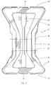
- Figure 3 depicts the base 9 which, in plan view, resembles a bow tie having flared ends 30 and 31 and a narrower neck 32.
- the perimeter of the base 9 is surrounded by a raised flange 33 which provides a member into which the arms 4 and 5 can be located and also provides strength and rigidity.
- the characteristics of the flange 33 are generally within the skill of the art and are determined in part by the dimensions of the arms and the base, the selection of materials and the size of the loads anticipated with a view to providing adequate strength and stiffness to the base.
- Apertures 10, 10', 11 and 11' are provided in the flange 33 at the intersection of the axes of rotation 36 and 37 of the arms 4 and 5. For example, two aligned apertures 10 and 10' are provided on the axis of rotation 36 of arm 4 to receive the axles 27 and 28.
- axles 27 and 28 are inserted into the apertures 10 and 10' during assembly by bending the flange 33 open to receive the arm 4 and allowing it to close resiliently back over the axles 27 and 28.
- the arm 5 is inserted into the base 9.
- the base 9 may be adapted with a slot 40 cut through its long axis to facilitate opening to receive the arms 4 an 5.
- cutouts 41 and 42 may be provided centrally in the flange 33 at the ends 30 and 31 of the base 9.
- All arms of the jack 1 may be constructed as shown in Figure 2 thereby simplifying tooling and manufacture.
- Arms 2, 3 and 5 are obtained by simply orienting an arm 4 of Figure 2 in a different position and connecting it in the combination of jack parts.
- upper arms 2 and 3 are similarly formed and similarly fitted into apertures 7, 7', 8 and 8' positioned on the axes of rotation of the upper arms in load rest 6 as shown in Figure 1.
- Many load rests do not require modification, ie., slots or cutouts, to force the arms into the apertures.
- axles can be extruded from the flanges of the arms or, alternatively, from the side flange of the base or a corresponding flange of a load rest to be inserted into apertures in the arms.
Landscapes
- Life Sciences & Earth Sciences (AREA)
- Engineering & Computer Science (AREA)
- Geology (AREA)
- Mechanical Engineering (AREA)
- Structural Engineering (AREA)
- Vehicle Cleaning, Maintenance, Repair, Refitting, And Outriggers (AREA)
- Current-Collector Devices For Electrically Propelled Vehicles (AREA)
Applications Claiming Priority (2)
| Application Number | Priority Date | Filing Date | Title |
|---|---|---|---|
| US551748 | 1983-11-14 | ||
| US08/551,748 US5692730A (en) | 1995-11-07 | 1995-11-07 | Pinless jack |
Publications (2)
| Publication Number | Publication Date |
|---|---|
| EP0773185A2 true EP0773185A2 (de) | 1997-05-14 |
| EP0773185A3 EP0773185A3 (de) | 1999-03-31 |
Family
ID=24202521
Family Applications (1)
| Application Number | Title | Priority Date | Filing Date |
|---|---|---|---|
| EP96308095A Withdrawn EP0773185A3 (de) | 1995-11-07 | 1996-11-07 | Bolzenloser Wagenheber |
Country Status (2)
| Country | Link |
|---|---|
| US (2) | US5692730A (de) |
| EP (1) | EP0773185A3 (de) |
Cited By (2)
| Publication number | Priority date | Publication date | Assignee | Title |
|---|---|---|---|---|
| WO2007000228A1 (de) * | 2005-06-24 | 2007-01-04 | Thyssenkrupp Bilstein Wagenheber Gmbh | Wagenheber |
| EP2181957A1 (de) | 2008-11-03 | 2010-05-05 | Scambia Industrial Developments AG | Grundplatte für Hebevorrichtungen |
Families Citing this family (9)
| Publication number | Priority date | Publication date | Assignee | Title |
|---|---|---|---|---|
| DE19623228C2 (de) * | 1996-06-11 | 1998-09-24 | Bayern Freistaat | Trennwerkzeug |
| US5975497A (en) * | 1998-01-06 | 1999-11-02 | Norco Industries, Inc. | Multipiece trunnion for a scissor type jack |
| IT1302736B1 (it) * | 1998-10-15 | 2000-09-29 | Carraro Spa | Sistema di sospensione ad assale oscillante, in particolare pertrattrici. |
| US6527251B1 (en) * | 1998-11-24 | 2003-03-04 | Norco Industries, Inc. | Jack with urethane brake |
| US6799749B1 (en) | 2003-12-15 | 2004-10-05 | Dura Global Technologies, Inc. | Slim pantograph jack |
| US8585017B2 (en) | 2009-11-30 | 2013-11-19 | Norco Industries, Inc. | Low profile scissor jack |
| US20130146823A1 (en) * | 2011-12-13 | 2013-06-13 | Force Protection Industries, Inc. | Compression kit for independent suspension system |
| JP2016132559A (ja) * | 2015-01-22 | 2016-07-25 | 和光工業株式会社 | パンタグラフ型ジャッキ |
| USD955084S1 (en) * | 2021-01-26 | 2022-06-14 | Ziwei LI | Cross base scissor jack |
Family Cites Families (9)
| Publication number | Priority date | Publication date | Assignee | Title |
|---|---|---|---|---|
| JPS5338624Y2 (de) * | 1974-05-08 | 1978-09-19 | ||
| US4802653A (en) * | 1987-11-16 | 1989-02-07 | Universal Tool & Stamping Co., Inc. | Scissors jack |
| US5176362A (en) * | 1991-04-26 | 1993-01-05 | Aluminum Company Of America | Vehicle jack assembly |
| US5139232A (en) * | 1991-05-20 | 1992-08-18 | Signet Industries | Nonmetallic automotive jack |
| FR2686869B1 (fr) * | 1992-02-05 | 1994-10-14 | Marc Landion | Cric pour le soulevement de vehicule automobile. |
| US5261644A (en) * | 1992-10-08 | 1993-11-16 | Seeburn Metal Products Limited | Plastic jack |
| US5303898A (en) * | 1993-03-17 | 1994-04-19 | Universal Tool & Stamping Company, Inc. | Open end construction for jack |
| DE4309022C2 (de) * | 1993-03-20 | 1995-01-05 | Bilstein August Gmbh Co Kg | Gelenk für Wagenheber |
| US5458316A (en) * | 1994-08-08 | 1995-10-17 | Larry Kip | Flexible protective boot for a jack screw |
-
1995
- 1995-11-07 US US08/551,748 patent/US5692730A/en not_active Expired - Lifetime
-
1996
- 1996-11-07 EP EP96308095A patent/EP0773185A3/de not_active Withdrawn
-
1997
- 1997-10-28 US US08/959,119 patent/US6012706A/en not_active Expired - Lifetime
Non-Patent Citations (1)
| Title |
|---|
| None |
Cited By (2)
| Publication number | Priority date | Publication date | Assignee | Title |
|---|---|---|---|---|
| WO2007000228A1 (de) * | 2005-06-24 | 2007-01-04 | Thyssenkrupp Bilstein Wagenheber Gmbh | Wagenheber |
| EP2181957A1 (de) | 2008-11-03 | 2010-05-05 | Scambia Industrial Developments AG | Grundplatte für Hebevorrichtungen |
Also Published As
| Publication number | Publication date |
|---|---|
| US6012706A (en) | 2000-01-11 |
| EP0773185A3 (de) | 1999-03-31 |
| US5692730A (en) | 1997-12-02 |
Similar Documents
| Publication | Publication Date | Title |
|---|---|---|
| US5692730A (en) | Pinless jack | |
| DE19781757B4 (de) | Aufhängungssystem | |
| US5628578A (en) | Alternate pinch bolt yoke construction | |
| US6122948A (en) | Method of hydroforming a front axle beam | |
| US4802653A (en) | Scissors jack | |
| EP0937910A1 (de) | Leitlasche einer beidseitig eingreifenden Zahnkette mit Öffnungsteilen zur Verringerung der Steifigkeit der Lasche | |
| CA2149001C (en) | Jack | |
| JPH08290717A (ja) | ガラスホルダー及び該ガラスホルダーを用いた窓ガラスの取付方法 | |
| EP0722401A1 (de) | Endabschnitt eines rahmenteils für ein fahrzeug | |
| US5975497A (en) | Multipiece trunnion for a scissor type jack | |
| US4848733A (en) | Vehicle jack assembly | |
| CA2098856C (en) | Improved open end construction for jack | |
| EP0487458A1 (de) | Gummibuchse für einen Drehstab | |
| EP0974475A1 (de) | Einzelradaufhängung in Schräg-, Längs- oder Verbundlenkerbauweise mit einem abgekoppelten Radträger | |
| EP1434946A1 (de) | Kugelgelenk | |
| DE10121329A1 (de) | Gelenkkreuz zur Verwendung in einer kompakten Universalgelenkanordnung | |
| EP0621230B1 (de) | Gelenk für Wagenheber | |
| US4836502A (en) | Pantograph jack | |
| DE60225947T2 (de) | Neigbares fahrzeug | |
| DE19912685A1 (de) | Antriebseinrichtung zum Verstellen eines in einem Spiegelgehäuse eines Kraftfahrzeug-Rückblickspiegels schwenkbar gelagerten Spiegelglasträgers | |
| EP0773186A2 (de) | Lagerzapfen für den Gebrauch bei einem Scherenwagenheber | |
| EP0790163B1 (de) | Halbscherenwagenheber | |
| US6799749B1 (en) | Slim pantograph jack | |
| CA1302389C (en) | Jack and components therefor | |
| US6957803B2 (en) | Slim pantograph jack with bearing spacer |
Legal Events
| Date | Code | Title | Description |
|---|---|---|---|
| PUAI | Public reference made under article 153(3) epc to a published international application that has entered the european phase |
Free format text: ORIGINAL CODE: 0009012 |
|
| AK | Designated contracting states |
Kind code of ref document: A2 Designated state(s): DE ES FR GB IT |
|
| PUAL | Search report despatched |
Free format text: ORIGINAL CODE: 0009013 |
|
| AK | Designated contracting states |
Kind code of ref document: A3 Designated state(s): DE ES FR GB IT |
|
| 17P | Request for examination filed |
Effective date: 19990922 |
|
| STAA | Information on the status of an ep patent application or granted ep patent |
Free format text: STATUS: THE APPLICATION HAS BEEN WITHDRAWN |
|
| 18W | Application withdrawn |
Effective date: 20041021 |