EP0773328A1 - Procédé pour stabiliser des sols mous - Google Patents
Procédé pour stabiliser des sols mous Download PDFInfo
- Publication number
- EP0773328A1 EP0773328A1 EP96308190A EP96308190A EP0773328A1 EP 0773328 A1 EP0773328 A1 EP 0773328A1 EP 96308190 A EP96308190 A EP 96308190A EP 96308190 A EP96308190 A EP 96308190A EP 0773328 A1 EP0773328 A1 EP 0773328A1
- Authority
- EP
- European Patent Office
- Prior art keywords
- ground
- consolidation
- piling
- soil
- stress
- Prior art date
- Legal status (The legal status is an assumption and is not a legal conclusion. Google has not performed a legal analysis and makes no representation as to the accuracy of the status listed.)
- Withdrawn
Links
- 238000000034 method Methods 0.000 title claims abstract description 60
- 230000000087 stabilizing effect Effects 0.000 title claims abstract description 5
- 239000000463 material Substances 0.000 claims abstract description 26
- 238000007596 consolidation process Methods 0.000 claims description 100
- 239000002689 soil Substances 0.000 claims description 86
- 238000010008 shearing Methods 0.000 claims description 23
- 239000004927 clay Substances 0.000 claims description 21
- 238000011065 in-situ storage Methods 0.000 claims description 14
- 230000018044 dehydration Effects 0.000 claims description 11
- 238000006297 dehydration reaction Methods 0.000 claims description 11
- 239000003415 peat Substances 0.000 claims description 10
- 239000003864 humus Substances 0.000 claims description 5
- 238000007711 solidification Methods 0.000 claims description 4
- 230000008023 solidification Effects 0.000 claims description 4
- 230000006641 stabilisation Effects 0.000 claims description 2
- 238000011105 stabilization Methods 0.000 claims description 2
- 238000006073 displacement reaction Methods 0.000 claims 1
- 238000005470 impregnation Methods 0.000 description 34
- 238000012360 testing method Methods 0.000 description 21
- 238000010276 construction Methods 0.000 description 18
- 238000013461 design Methods 0.000 description 16
- 230000000694 effects Effects 0.000 description 15
- 238000010586 diagram Methods 0.000 description 14
- 239000012530 fluid Substances 0.000 description 14
- 238000011068 loading method Methods 0.000 description 13
- 230000006872 improvement Effects 0.000 description 12
- XLYOFNOQVPJJNP-UHFFFAOYSA-N water Substances O XLYOFNOQVPJJNP-UHFFFAOYSA-N 0.000 description 11
- 238000002347 injection Methods 0.000 description 9
- 239000007924 injection Substances 0.000 description 9
- 230000006378 damage Effects 0.000 description 8
- 230000006835 compression Effects 0.000 description 7
- 238000007906 compression Methods 0.000 description 7
- 230000035515 penetration Effects 0.000 description 7
- 230000008569 process Effects 0.000 description 7
- 239000004576 sand Substances 0.000 description 6
- 239000011800 void material Substances 0.000 description 6
- 230000009471 action Effects 0.000 description 5
- 238000011835 investigation Methods 0.000 description 5
- 239000011148 porous material Substances 0.000 description 4
- 239000003673 groundwater Substances 0.000 description 3
- 239000004568 cement Substances 0.000 description 2
- 230000007423 decrease Effects 0.000 description 2
- 239000004570 mortar (masonry) Substances 0.000 description 2
- 230000002265 prevention Effects 0.000 description 2
- 230000009666 qualitative growth Effects 0.000 description 2
- 230000009663 quantitative growth Effects 0.000 description 2
- 238000006467 substitution reaction Methods 0.000 description 2
- 240000007594 Oryza sativa Species 0.000 description 1
- 235000007164 Oryza sativa Nutrition 0.000 description 1
- 238000009825 accumulation Methods 0.000 description 1
- 230000005540 biological transmission Effects 0.000 description 1
- 230000008859 change Effects 0.000 description 1
- 239000000470 constituent Substances 0.000 description 1
- 238000007796 conventional method Methods 0.000 description 1
- 230000007547 defect Effects 0.000 description 1
- 238000001035 drying Methods 0.000 description 1
- 230000002708 enhancing effect Effects 0.000 description 1
- 238000012423 maintenance Methods 0.000 description 1
- 238000007726 management method Methods 0.000 description 1
- 230000007246 mechanism Effects 0.000 description 1
- 239000000203 mixture Substances 0.000 description 1
- 239000002245 particle Substances 0.000 description 1
- 230000002787 reinforcement Effects 0.000 description 1
- 235000009566 rice Nutrition 0.000 description 1
- 229920006395 saturated elastomer Polymers 0.000 description 1
- 239000000243 solution Substances 0.000 description 1
- 230000003068 static effect Effects 0.000 description 1
- 239000000126 substance Substances 0.000 description 1
- 238000009736 wetting Methods 0.000 description 1
Images










Classifications
-
- E—FIXED CONSTRUCTIONS
- E02—HYDRAULIC ENGINEERING; FOUNDATIONS; SOIL SHIFTING
- E02D—FOUNDATIONS; EXCAVATIONS; EMBANKMENTS; UNDERGROUND OR UNDERWATER STRUCTURES
- E02D3/00—Improving or preserving soil or rock, e.g. preserving permafrost soil
- E02D3/12—Consolidating by placing solidifying or pore-filling substances in the soil
-
- E—FIXED CONSTRUCTIONS
- E02—HYDRAULIC ENGINEERING; FOUNDATIONS; SOIL SHIFTING
- E02D—FOUNDATIONS; EXCAVATIONS; EMBANKMENTS; UNDERGROUND OR UNDERWATER STRUCTURES
- E02D1/00—Investigation of foundation soil in situ
- E02D1/02—Investigation of foundation soil in situ before construction work
-
- E—FIXED CONSTRUCTIONS
- E02—HYDRAULIC ENGINEERING; FOUNDATIONS; SOIL SHIFTING
- E02D—FOUNDATIONS; EXCAVATIONS; EMBANKMENTS; UNDERGROUND OR UNDERWATER STRUCTURES
- E02D2250/00—Production methods
- E02D2250/003—Injection of material
Definitions
- the present invention relates to a method of stabilizing soft ground which supports roads, river banks or the like and soft ground which is susceptible to movement resulting from earthquakes.
- a particular problem with the piling method is that it is prima face effective for temporarily bringing ground disturbed by sliding destruction, earthquakes, or the like back to the old condition provided that the height of the soiling structure thereon lies within a certain range, but it is not suited for permanently recovering or enhancing the strength of disturbed ground, or preventing seismic disasters.
- a piling structure laid on soft ground must be normally stable with respect to piling loads, and dynamic loads and vibrations produced by traffic loads. In addition to such piling, and traffic loads, the piling structure must also resist vibrations produced by an earthquake.
- An essential requirement for achieving the stabilization of such a piling structure is to improve the property of the soil forming the piling soil structure and the foundation without disturbing them, so that the strength needed for design and construction can be instantaneously created, thereby constituting a homogeneous pre-consolidated (over-consolidated) ground layer in which the piling structure is united with the foundation.
- a primary object of the present invention is to provide a consistent solution to the following five problems the aforesaid conventional piling methods involve in connection with (1) consolidation or construction time, (2) construction environment, (3) design management, and construction control, (4) restoration of ground disturbed by sliding destruction, and ground or structures damaged by an earthquake, and (5) applicability to prevention of ground and structures against disaster.
- the present invention has been accomplished with the aforesaid object in mind, and is basically characterized by improving the nature of the soil of the ground to be reconstructed while the ground is not disturbed at all, using an instantaneous consolidation method, so that the ground can be in situ reconstructed within 24 hours in an instantaneous operation on the basis of four basic principles for soft ground improvement, viz., (1) consolidation and dehydration, (2) drainage, (3) solidification, and (4) replacement.
- the present invention is also applicable to (1) every soft ground inclusive of natural stratified ground, man-made ground, and ground disturbed by destruction, (2) free creation of the required strength over the range needed in view of design and construction according to a ground improvement plan, (3) restoration and reinforcement of ground disturbed by destruction, and (4) prevention of ground and structures again seismic disasters.
- the present invention provides a technique that makes use of the effective soil covering stress of the original ground to reconstruct it into a stable ground layer capable of resisting piling loads, traffic loads, and vibration loads additionally applied to the original ground.
- FIG. 1 illustrates a process wherein using a specific impregnation machine, a specifically formulated impregnation material is injected into ground by a consolidation impregnation method controlled according to the design and construction standards, so that there can be obtained a homogeneously stable yet complex ground zone in which a solidified portion is united with an over-consolidated portion obtained by compression effect due to in-situ dehydration and drainage by consolidation, and post-injection in-situ replacement and solidification effect.
- FIG. 2 illustrates a process wherein by effecting the aforesaid consolidation impregnation method using the impregnation material being injected as a load in place of a piling or other load, a soft and viscous ground zone or a loose sandy ground zone can be destroyed to form crevices therein.
- FIG. 3 illustrates a process wherein with a further continued injection of the impregnation material on the same breaking criteria, the ground zone is successively destroyed to cause quantitative and qualitative growth of the crevices, so that the impregnation material starts to flow while the crevices are filled therewith, thereby creating a sheet form of fluid body in an oblique or vertical direction.
- FIG. 4 illustrates a process where while the fluid body flows through passages and grows, ground portions contiguous to the breaking interfaces are in situ subjected to forcibly rapid loading and dehydration actions in a transverse direction.
- FIG. 5 illustrates a process wherein by the in-situ loading and dehydration actions of the fluid body, pore water is entrained, simultaneously with the injection of the impregnation material, from the ground to be consolidated into the fluid body, and then dynamically discharged, and during the injection of the impregnation material, the water is discharged mainly through water discharge passages formed by boundaries between the ground to be consolidated and the fluid body, and then discharged into underground, and ground-surface sand layers together with water separated from the impregnation material.
- FIG. 6 illustrates a process where by a chain effect of the fluid body on in-situ loading, dehydration and drainage, the ground to be improved can be instantaneously consolidated without being disturbed at all, resulting in a successive ground strength increase, and the fluid body itself is solidified within 24 hours in its as-injected state to create an in-situ solidified replacement skeleton structure in the ground to be consolidated.
- FIG. 7 is diagram showing the relation between consolidation yield stress and pre-consolidation stress.
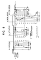
- FIG. 8 illustrates in section a plan for the creation of a road with a low piling structure laid thereon.
- FIG. 9 a table showing the nature of the soil forming the ground to be reconstructed, and a profile diagram showing the effective soil covering stress profile of a piling structure.
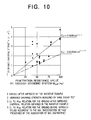
- FIG. 10 is a diagram showing the relation between penetration resistance values obtained by Swedish sounding tests performed at a depth of up to 5 meters and undrained shearing strength values (for the reconstructed ground) obtained by vane shear tests.
- FIG. 11 is diagrams for making estimation of the effect on ground improvement by cone penetration tests using a portable cone penetrometer.
- FIG. 12 is a diagram showing the relation between consolidation yield stress Pc and pre-consolidation stress Pc', both in tf/m 2 , to thereby illustrate the first results of the reconstructed peat ground.
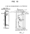
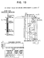
- FIG. 13 is a diagram showing the second results of the reconstructed peat ground.
- FIG. 14 is a diagram showing the third results of the reconstructed peat ground.
- FIG. 15 is a table showing the constituent of the soil forming the ground to be reconstructed, and a diagram showing a plan for reconstructing a road with a low piling structure laid thereon.
- FIG. 16 is a diagram providing an illustration of how a piling structure subsides.
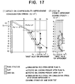
- FIG. 17 is a diagram showing the effective soil covering stress profile of piled ground (clay of marine origin), and the results of ground improvement.
- FIG. 18 is a diagram showing the relation between pre-consolidation stress Pc' and undrained shearing strength Cu (of clay of marine origin).
- FIG. 19 is a diagram showing the effective soil covering stresses of the original ground (clay of river origin) and piled ground, the consolidation yield stress of the original ground, and the consolidation yield stress of the original ground (clay of river origin) upon reconstructed.
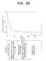
- FIG. 20 is a diagram providing an illustration of how the ground subsides during reconstruction, and after reconstruction.
- FIG. 21 is a diagram showing the void ratio of undrained shearing strength of the ground before and after reconstruction.
- soil covering pressure or stress Pressure that a horizontal plane at a certain depth of ground receives by the weight of soil placed above it is called soil covering pressure or stress.
- the pressure ⁇ z ' is a sort of pressure transmitted directly between soil particles, and called effective stress.
- the soil covering pressure (stress) represented in terms of effective stress is then called effective soil covering pressure (stress).
- This invention provides a ground improving method capable of creating ground unlikely to subside by means of the aforesaid instantaneous consolidation technique, according to which impregnation of ground can be used in place of loading such as pilling based on the consolidation principles mentioned above.
- This invention provides a technique which enables over-consolidated soil (ground) having the required strength to be instantaneously created at the depth, and over the range, needed for design, using the instantaneous consolidation method.
- pre-consolidated ground comprising an integral structure of the foundation and a piling structure laid thereon.
- pre-consolidated ground used herein is understood to refer to improved and reinforced ground which can resist every external force newly added to the effective soil covering pressure of the original ground, for instance, static loads produced by a piling structure laid thereon or structures built up thereon, dynamic loads produced by traffic vehicles, and loads produced by vibrations, and earthquakes.
- a predetermined amount of one impregnation material selected from the group consisting of mortar material, cement material, and a mixture of mortar and cement materials is injected at a predetermined pressure into very soft, viscous ground or loose sandy ground through a preselected array of injection points.
- the soft ground is destroyed to form crevices therein, which are then filled with the impregnation material.
- both the amount of the material impregnated and the impregnation pressure are controlled according to the aforesaid design, so that the end degree of consolidation can be instantaneously achieved.
- Example 1 Instantaneous consolidation method by impregnation of ground .
- FIG. 7 clarifies the effect of the inventive instantaneous consolidation method by impregnation of ground through an accumulation of experimental data.
- the numbers on the abscissa indicate a consolidation load or, more exactly, the consolidation yield stress Pc of the original ground found by soil testing, and the consolidation yield stress, again found by soil testing, of the ground improved by the application of the inventive method of impregnation of ground.
- the latter consolidation yield stress is denoted as pre-consolidation stress Pc' to define around the former consolidation yield stress.
- the numbers on the left ordinate stand for void ratio e and a compression index Cc while the numbers on the right ordinate represent undrained shearing strength Cu. Data on void ratio e, compression index Cc, and undrained shearing strength Cu of the ground before and after reconstruction are plotted with respect to the consolidation load on the abscissa.
- White symbols refer to the original ground before and after reconstruction, and ground with soil laid on it, while black symbols refer to the ground after reconstruction. It is here to be noted that the ground with a soiling structure laid on it was created before seven years with a piling structure of 4.5 meters in height.
- FIG. 8 shows a road widening project in section for a given road with a new piling structure placed on an adjoining rice field, and penetration resistance values of the ground before and after reconstruction for the purpose of comparison.
- FIG. 9 illustrates the soil constitution of the ground to be improved, the effective soil covering stress, consolidation yield stress, and pre-consolidation stress profiles of the ground to be improved, and ground with a piling structure laid on it.
- the ground to be reconstructed includes a surface soil layer of 0.6 meters in thickness, beneath which highly compressible, very soft, and organic viscous soil composed mainly of peat or humus soil is distributed at a thickness of about 4.0 meters, and a relatively rigid and hard subsoil layer composed of alternate sub-layers of sandy soil, silt soil, and viscous and sandy soils.
- the very soft layer having a depth of about 4.0 meters must be reconstructed.
- the maximum load that the ground has so far received, for instance, through accumulated loads of deposits constituting the ground is consolidation yield stress Pc and, in many cases, the profile of consolidation yield stress Pc within the ground is in substantial agreement with that of the effective soil covering stress of the original ground.
- a load produced thereby causes the profile line of consolidation yield stress Pc of the original ground to become close to that of the piled ground layer with the progress of consolidation. Therefore, the piled ground layer continues to subside until the profile line of the consolidation yield stress of the original ground coincides with that of the effective soil covering stress of the piled ground layer.
- the consolidation yield stress of the improved ground obtained by the inventive method viz., the value of pre-consolidation stress Pc' is set on or above the profile line of the effective soil covering stress of the piled ground layer, any ground subsidence would not theoretically occur. Indeed, the thus improved pre-consolidated ground is observed to undergo no subsidence at all, or an allowable, if any, degree of subsidence, and is found to be effective for earthquakes as well.
- such concepts underlie the present invention; it is the inventive method of stabilizing piled ground, or ground with a low piling structure placed on it that enables pre-consolidation stress Pc' of the soft ground to be reconstructed to be set on or above the profile line of the effective soil covering stress produced by piling, traffic, and seismic loads.
- the inventive method is distinguishable over the prior art in the following points.
- curves 3 and 4 show underground stress profiles wherein the consolidation stresses Pd (pre-consolidation stresses Pc') as calculated above are distributed in the ground to be reconstructed, corresponding to the effective soil covering stress of the original ground.
- pile height as calculated as traffic loads is 2.5 meters if pile height as planned is 1.0 meter
- pile height as calculated as traffic loads is 3.2 meters if pile height as planned is 1.0 meter.
- Deposits constituting the ground to be reconstructed are mainly composed of a very soft clay layer of marine origin and of about 10 meters in thickness, with diluvial hard clay and sand soil distributed beneath it.
- FIGS. 17 and 18 The results of effect of the inventive method on low piling structures are concisely illustrated in FIGS. 17 and 18, from which it is found that the effect on ground improvement was achieved as initially planned.
- Deposits constituting the ground to be reconstructed form a very soft ground layer of about 4.8 meters in thickness and composed mainly of clay of river origin, beneath which there is a layer composed of a gravel-containing sand layer having a relatively high density.
- a sand mat of 0.4 meters in thickness was placed on ground, and a first piling structure having a critical height of 1.5 meters was laid on the sand mat. After the lapse of 22 days during which they were allowed to stand, the ground was reconstructed by the inventive method and, in three days later during which the ground was let alone, a second piling structure of 2.5 meters in height was laid on the ground. In this way, the ground was rapidly reconstructed within a total period of 27 days.
- the piling structure remains uncosolidated because its soil covering stress is lower than its effective soil covering stress, although the original ground is an over-consolidated clay layer.
- the consolidation yield stress (pre-consolidation stress) of the ground to be reconstructed is distributed in a pre-consolidation region lying above the profile line of the effective soil covering stress due to the piling loads, so that the ground can be stable with respect to both the loads produced by these piling structures and both the vibration loads produced by railway trains.
- FIGS. 19, 20 and 21 are the results the stability of the piled ground for railway tracks, which was obtained by the application of the inventive method to clay of river origin. From these figures, it is found that the effect on ground improvement is achieved as initially planned.
- the compressibility of the original ground and piling structure are Pc ⁇ 10 tf/m 2 while the consolidation yield stress of the reconstructed ground is Pc' > 10 to 18 tf/m 2 , indicating that apparent improvements in both strength and compressibility are obtained.
Landscapes
- Engineering & Computer Science (AREA)
- Life Sciences & Earth Sciences (AREA)
- Structural Engineering (AREA)
- Mining & Mineral Resources (AREA)
- Soil Sciences (AREA)
- General Life Sciences & Earth Sciences (AREA)
- Paleontology (AREA)
- Civil Engineering (AREA)
- General Engineering & Computer Science (AREA)
- Agronomy & Crop Science (AREA)
- Environmental & Geological Engineering (AREA)
- Analytical Chemistry (AREA)
- Chemical & Material Sciences (AREA)
- Investigation Of Foundation Soil And Reinforcement Of Foundation Soil By Compacting Or Drainage (AREA)
- Consolidation Of Soil By Introduction Of Solidifying Substances Into Soil (AREA)
Applications Claiming Priority (4)
| Application Number | Priority Date | Filing Date | Title |
|---|---|---|---|
| JP32938895 | 1995-11-13 | ||
| JP329388/95 | 1995-11-13 | ||
| JP322396/95 | 1995-11-16 | ||
| JP7322396A JPH09143973A (ja) | 1995-11-16 | 1995-11-16 | 道路、堤防、造成地盤などに発生する粘性土地盤の変状防止工法と地震災害の防災工法 |
Publications (1)
| Publication Number | Publication Date |
|---|---|
| EP0773328A1 true EP0773328A1 (fr) | 1997-05-14 |
Family
ID=26570799
Family Applications (1)
| Application Number | Title | Priority Date | Filing Date |
|---|---|---|---|
| EP96308190A Withdrawn EP0773328A1 (fr) | 1995-11-13 | 1996-11-13 | Procédé pour stabiliser des sols mous |
Country Status (4)
| Country | Link |
|---|---|
| EP (1) | EP0773328A1 (fr) |
| KR (1) | KR970027540A (fr) |
| CN (1) | CN1156777A (fr) |
| CA (1) | CA2190212A1 (fr) |
Cited By (2)
| Publication number | Priority date | Publication date | Assignee | Title |
|---|---|---|---|---|
| WO2004044335A1 (fr) * | 2002-11-13 | 2004-05-27 | Uww-Licensing Oy | Procede permettant de reduire le potentiel de liquefaction de sols de fondation |
| EP1956147A1 (fr) * | 2007-02-09 | 2008-08-13 | Geosec S.r.l. | Procédé de protection sismique locale pour des sites de construction existants et/ou éventuels destiné aux régions des fondations entourant la construction d'un immeuble |
Families Citing this family (2)
| Publication number | Priority date | Publication date | Assignee | Title |
|---|---|---|---|---|
| CN103321205B (zh) * | 2013-06-20 | 2015-06-24 | 南京盼源工程技术有限公司 | 天然沉积软黏土地基扰动密实法 |
| CN113047268B (zh) * | 2021-03-11 | 2022-10-04 | 福建宝丰管桩有限公司 | 一种稳定系数高且具有防沉降功能的混凝土管桩 |
Citations (3)
| Publication number | Priority date | Publication date | Assignee | Title |
|---|---|---|---|---|
| US4309129A (en) | 1977-05-23 | 1982-01-05 | Yuichiro Takahashi | Method and apparatus for improving the strength of soft viscous ground |
| US4540316A (en) | 1981-03-19 | 1985-09-10 | Yuichiro Takahashi | Composition for improving strength of soft ground containing organic matter, and method of improving strength of soft ground by utilizing said composition |
| GB2258670A (en) * | 1991-08-14 | 1993-02-17 | Nit Co Ltd | Improving ground |
-
1996
- 1996-11-13 CN CN96121005A patent/CN1156777A/zh active Pending
- 1996-11-13 EP EP96308190A patent/EP0773328A1/fr not_active Withdrawn
- 1996-11-13 CA CA002190212A patent/CA2190212A1/fr not_active Abandoned
- 1996-11-13 KR KR1019960053605A patent/KR970027540A/ko not_active Withdrawn
Patent Citations (3)
| Publication number | Priority date | Publication date | Assignee | Title |
|---|---|---|---|---|
| US4309129A (en) | 1977-05-23 | 1982-01-05 | Yuichiro Takahashi | Method and apparatus for improving the strength of soft viscous ground |
| US4540316A (en) | 1981-03-19 | 1985-09-10 | Yuichiro Takahashi | Composition for improving strength of soft ground containing organic matter, and method of improving strength of soft ground by utilizing said composition |
| GB2258670A (en) * | 1991-08-14 | 1993-02-17 | Nit Co Ltd | Improving ground |
Non-Patent Citations (1)
| Title |
|---|
| JASPERSE & RYAN: "geotech import : deep soil mixing", CIVIL ENGINEERING, no. 12, December 1987 (1987-12-01), NEW YORK, USA, pages 66 - 68, XP002025905 * |
Cited By (4)
| Publication number | Priority date | Publication date | Assignee | Title |
|---|---|---|---|---|
| WO2004044335A1 (fr) * | 2002-11-13 | 2004-05-27 | Uww-Licensing Oy | Procede permettant de reduire le potentiel de liquefaction de sols de fondation |
| US7290962B2 (en) | 2002-11-13 | 2007-11-06 | Benefil Worldwide Oy | Method for reducing the liquefaction potential of foundation soils |
| US7517177B2 (en) | 2002-11-13 | 2009-04-14 | Benefil Worldwide Oy | Method for the reduction of liquefaction potential of foundation soils under the structures |
| EP1956147A1 (fr) * | 2007-02-09 | 2008-08-13 | Geosec S.r.l. | Procédé de protection sismique locale pour des sites de construction existants et/ou éventuels destiné aux régions des fondations entourant la construction d'un immeuble |
Also Published As
| Publication number | Publication date |
|---|---|
| KR970027540A (ko) | 1997-06-24 |
| CN1156777A (zh) | 1997-08-13 |
| CA2190212A1 (fr) | 1997-05-14 |
Similar Documents
| Publication | Publication Date | Title |
|---|---|---|
| Mitchell et al. | Performance of a stone column foundation | |
| Elias et al. | Mechanically stabilized earth walls and reinforced soil slopes: design and construction guidelines (updated version) | |
| Wahls | Design and construction of bridge approaches | |
| Demir et al. | Large scale field tests on geogrid-reinforced granular fill underlain by clay soil | |
| Christopher et al. | Reinforced Soil Structures–Volume I: Design and Construction Guidelines | |
| Schaefer et al. | Design guide for improved quality of roadway subgrades and subbases | |
| Elias | Mechanically Stabilized Earth Walls and Reinforced Soil Slopes Design and Construction Guidelines: FHWA Demonstration Project 82, Reinforced Soil Structures WSEW [ie MSEW] and RSS. | |
| Foott et al. | Test fill at Chek Lap Kok, Hong Kong | |
| Rutherford | Design manual for excavation support using deep mixing technology | |
| Trenter et al. | a Model Specification for Engineered Fills for Building Purposes. | |
| Cantré et al. | Installation of fine-grained organic dredged materials in combination with geosynthetics in the German DredgDikes research dike facility | |
| CA2190212A1 (fr) | Methode permettant de prevenir les changements dans la nature des sols visqueux que l'on trouve dans les fondations creees pour les routes, remblais ou autres, et pour prevenir les dommages causes par les tremblements de terre | |
| Christopher et al. | Mechanically stabilized earth walls and reinforced soil slopes design and construction guidelines | |
| Bridle et al. | EMPINGHAM DAM-DESIGN, CONSTRUCTION AND PERFORMANCE. | |
| Tjie-Liong | Geosynthetics application in Indonesia–a case histories | |
| Gerber et al. | Ground Improvement for Liquefaction Mitigation at Sevier Bridge Dam | |
| Guler et al. | Centrifuge and full scale models of geotextile reinforced walls and several case studies of segmental retaining walls in Turkey | |
| JPH09195257A (ja) | 道路、堤防、造成地盤などに発生する粘性土地盤の変状防止工法と地震災害の防災工法 | |
| JPH09143973A (ja) | 道路、堤防、造成地盤などに発生する粘性土地盤の変状防止工法と地震災害の防災工法 | |
| EP0774543A1 (fr) | Méthode de traitement pour la consolidation des sols | |
| Blackwood et al. | Geogrid reinforced embankment constructed over peat soils in Clark County, Washington: Design and field performance | |
| Siddique et al. | Characteristic features of soft ground engineering in Bangladesh | |
| Miura et al. | Theory and Practice of Earth Reinforcement: Proceedings of the international geotechnical symposium, Kyushu, 5-7 October 1988 | |
| Dalwadi et al. | Design and construction of a road embankment using cellular foundation mattress over weak ground | |
| Zaytsev et al. | Physical modelling and monitoring of the subgrade on weak foundation and its reinforcing with geosynthetics |
Legal Events
| Date | Code | Title | Description |
|---|---|---|---|
| PUAI | Public reference made under article 153(3) epc to a published international application that has entered the european phase |
Free format text: ORIGINAL CODE: 0009012 |
|
| AK | Designated contracting states |
Kind code of ref document: A1 Designated state(s): DE FR GB NL |
|
| STAA | Information on the status of an ep patent application or granted ep patent |
Free format text: STATUS: THE APPLICATION IS DEEMED TO BE WITHDRAWN |
|
| 18D | Application deemed to be withdrawn |
Effective date: 19971115 |