EP0773376B1 - Palier de vilebrequin - Google Patents
Palier de vilebrequin Download PDFInfo
- Publication number
- EP0773376B1 EP0773376B1 EP95810711A EP95810711A EP0773376B1 EP 0773376 B1 EP0773376 B1 EP 0773376B1 EP 95810711 A EP95810711 A EP 95810711A EP 95810711 A EP95810711 A EP 95810711A EP 0773376 B1 EP0773376 B1 EP 0773376B1
- Authority
- EP
- European Patent Office
- Prior art keywords
- bearing
- crankshaft
- legs
- bedplate
- shell
- Prior art date
- Legal status (The legal status is an assumption and is not a legal conclusion. Google has not performed a legal analysis and makes no representation as to the accuracy of the status listed.)
- Expired - Lifetime
Links
Images

Classifications
-
- F—MECHANICAL ENGINEERING; LIGHTING; HEATING; WEAPONS; BLASTING
- F16—ENGINEERING ELEMENTS AND UNITS; GENERAL MEASURES FOR PRODUCING AND MAINTAINING EFFECTIVE FUNCTIONING OF MACHINES OR INSTALLATIONS; THERMAL INSULATION IN GENERAL
- F16C—SHAFTS; FLEXIBLE SHAFTS; ELEMENTS OR CRANKSHAFT MECHANISMS; ROTARY BODIES OTHER THAN GEARING ELEMENTS; BEARINGS
- F16C25/00—Bearings for exclusively rotary movement adjustable for wear or play
- F16C25/02—Sliding-contact bearings
-
- F—MECHANICAL ENGINEERING; LIGHTING; HEATING; WEAPONS; BLASTING
- F16—ENGINEERING ELEMENTS AND UNITS; GENERAL MEASURES FOR PRODUCING AND MAINTAINING EFFECTIVE FUNCTIONING OF MACHINES OR INSTALLATIONS; THERMAL INSULATION IN GENERAL
- F16C—SHAFTS; FLEXIBLE SHAFTS; ELEMENTS OR CRANKSHAFT MECHANISMS; ROTARY BODIES OTHER THAN GEARING ELEMENTS; BEARINGS
- F16C9/00—Bearings for crankshafts or connecting-rods; Attachment of connecting-rods
- F16C9/02—Crankshaft bearings
-
- F—MECHANICAL ENGINEERING; LIGHTING; HEATING; WEAPONS; BLASTING
- F16—ENGINEERING ELEMENTS AND UNITS; GENERAL MEASURES FOR PRODUCING AND MAINTAINING EFFECTIVE FUNCTIONING OF MACHINES OR INSTALLATIONS; THERMAL INSULATION IN GENERAL
- F16C—SHAFTS; FLEXIBLE SHAFTS; ELEMENTS OR CRANKSHAFT MECHANISMS; ROTARY BODIES OTHER THAN GEARING ELEMENTS; BEARINGS
- F16C23/00—Bearings for exclusively rotary movement adjustable for aligning or positioning
- F16C23/02—Sliding-contact bearings
Definitions
- the invention relates to a crankshaft bearing according to the Preamble of claim 1.
- crankshaft bearing is known from CH-PS 620 023, with the guide surfaces on the bearing cover and counter surfaces are designed in a suitable manner in the housing, such that that when installing the cover there is no danger of a Clamping exists.
- this known bearings a play-free arrangement of the lid do not manufacture.
- the base plate of the diesel engine is by means of Tie rod with a housing and a cylinder jacket tied together. Due to the tensile forces increases in the horizontal direction for the bearing cover intended space between the counter surfaces by a few Tenths of a millimeter.
- the lid must also be installed tie rods that are not under tension may be possible. So there is the problem of how the gaps between the lid and Mating surfaces after assembly and after tensioning the tie rod is present, can be removed.
- the crankshaft bearing has a bearing cover that two legs and two each associated with the legs Flanges includes.
- the flanges can be Clamp screws against a base plate; be there at the same time the legs at joints against one Bearing shell of the base plate pressed.
- According to the invention is between the legs and their associated Flanges each have a special lateral recess in the Bearing cap provided due to the depth of this recess and under the influence of the screw forces Legs Pairs of forces that spread the legs cause the legs with respect to Center of the camp to be deflected outwards.
- the dependent claims 2 to 9 relate to special embodiments of the inventive Camp.
- the subject of claim 10 is a diesel engine.
- Fig. 1 shows the following parts of a diesel engine: one Base plate 1, a housing 2, a cylinder jacket 3, Tie rod 4 and an opening 5 for a crankshaft bearing.
- tensioned tie rods 4 is the horizontal one Diameter D of the opening 5 by a few tenths of a millimeter larger than with tension rods not tensioned.
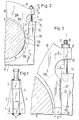
- the bearing of the crankshaft 6 in FIG. 2 includes one Bearing shell 10, which is arranged in the base plate 1, and a bearing cover 20, which on flanges 21 (with Holes 71) by means of studs 7 (nuts 70) the base plate 1 (with threads 72) attached and on this is clamped (clamping force P).
- Stud bolts 7 can also be provided with cap screws his.
- the leg 22 of the bearing cap 20, the upward is delimited by the dotted line 205, at the Butt 210 pressed against the bearing shell 10. Is between the leg 22 and the flange 21 According to the invention, a recess 23 is provided. They don't Half of the bearing shown is mirror-symmetrical educated.
- a pair of forces acts on the leg 22, the on the one hand by the one acting on line 205 Clamping force P and on the other hand by the Impact 210 acting counterforce P 'is formed.
- On corresponding pair of forces acts on the one not shown Leg 22 of the other half of the bearing.
- the Recesses 23 are the pairs of forces with bending moments connected, which cause the legs 22 to spread, where the tips of the legs are in relation to the center of the Camp are deflected outwards.
- the outside Flanks of the legs 22 occur due to the spread of the base plate 1 on flat support surfaces 201 in Contact.
- the distance between the outer flanks of the both legs 22 must be at least in the spread state be around 0.8 - 1.2 mm larger than in the non-spread.
- the bearing cap 20 without Assemble difficulties. So that the spread of Leg 22 for contact with the contact surfaces 201 leads, the recess 23 must be sufficiently deep: Between the plane through the bearing surface 201 and the Recess 23 is a space, the maximum Depth d - measured perpendicular to the contact surface 201 - must be greater than a length e. This length is e at least one third, preferably half the thickness c the bearing shell. This thickness c is around 4 to 10% of the shaft diameter, which is around 0.4 to 1 m is. The distance between the outer flanks 201 of the both legs 22 is at least in the spread state around 0.4 - 1.2 mm larger than in the unexpanded.
- FIG. 4 The oblique view of Figure 4 shows one half of a vertically cut crankshaft bearing. Compared to the Representations in Figures 2 and 3 is additional here see a lubricant supply 107, 108 and 109. The lubricant is dash-dotted indicated line 107 supplied. After forwarding through the channel 108, the lubricant passes through the Distributor 109 in the gap 60 (see Fig.2).
- the bearing cover 20 in Figures 2 to 4 is in the essentially monolithic; i.e. it is a casting. Its bearing surface 206 is - not shown - by a layer of cast bearing metal is formed.
- the Bearing cover 20 can also have a bearing shell 200, as shown in Fig.5.
- the bearing shell 200 has also a layer, namely layer 206 ' cast bearing metal.
- the thread is 72 for screw 7 in the middle of the bearing, i.e. in the Joint 210, arranged.
Landscapes
- Engineering & Computer Science (AREA)
- General Engineering & Computer Science (AREA)
- Mechanical Engineering (AREA)
- Shafts, Cranks, Connecting Bars, And Related Bearings (AREA)
- Cylinder Crankcases Of Internal Combustion Engines (AREA)
Claims (10)
- Palier pour un vilebrequin (6) qui est disposé entre une coupelle de palier (10) sur une plaque de base (1) et un couvercle de palier (20) du palier, où le couvercle de palier comprend deux branches (22) et deux brides (21) associées respectivement aux branches, où les brides peuvent être serrées par des boulons (7) contre la plaque de base (1) et en même temps les branches peuvent être appliquées à des points d'impact (210) contre la coupelle de palier (10), qu'il est prévu entre les branches (22) et leurs brides associées (21) respectivement un évidement latéral (23) dans le couvercle de palier, caractérisé en ce que la profondeur de l'évidement est dimensionnée de façon que sous l'action des forces de vissage s'appliquent aux branches des paires de forces (P, P') qui provoquent un écartement des branches, où les branches, relativement au centre du palier, sont déviées vers l'extérieur.
- Palier de vilebrequin selon la revendication 1, caractérisé en ce qu'il est prévu pour les flancs extérieurs des branches (22) à la plaque de base (1) respectivement une surface d'application plane (201), que l'évidement (23) présente relativement au plan, du fait de cette surface d'application une profondeur maximale (d) qui est supérieure à un tiers, de préférence supérieure à la moitié de l'épaisseur (c) de la coupelle de palier, cette épaisseur représentant environ 4 à 10% du diamètre de l'arbre, et le diamètre de l'arbre est d'environ 0,4 à 1 m.
- Palier de vilebrequin selon la revendication 1 ou 2, caractérisé en ce que le couvercle de palier (20) et la coupelle de palier (10) forment un palier pour le vilebrequin (6) dont le diamètre est plus grand d'environ 0,5 mm que le diamètre du vilebrequin.
- Palier de vilebrequin selon l'une des revendications 1 à 3, caractérisé en ce que le couvercle de palier (20) est essentiellement monolithe et présente une surface de palier (206) qui est formée par une couche en métal de palier coulé.
- Palier de vilebrequin selon l'une des revendications 1 à 4, caractérisé en ce que la surface de palier (106, 206), à part par la coupelle de palier (10) de la plaque de base (1), est formée par une deuxième coupelle de palier (200) du couvercle de palier (20), la deuxième coupelle de palier présentant une couche (206') en métal de palier coulé.
- Palier de vilebrequin selon l'une des revendications 1 à 5, caractérisé en ce que les brides (21) sont fixées par des boulons filetés (7) ou des boulons à tête à la plaque de base (1) et sont serrées sur celle-ci.
- Palier de vilebrequin selon l'une des revendications 1 à 6, caractérisé en ce que les surfaces de palier (106, 206) se situent des deux côtés du point d'impact (210) entre la branche (22) et la coupelle de palier (10) de la plaque de base (1) sensiblement sur un plan tangentiel commun.
- Palier de vilebrequin selon l'une des revendications 1 à 7, caractérisé en ce que l'écart entre les flancs extérieurs (201) des deux branches (22), à l'écart écarté, est au moins environ 0,4-1,2 mm plus grand qu'à l'état non écarté.
- Palier de vilebrequin selon l'une des revendications 1 à 8, caractérisé en ce que le couvercle de palier (20) est disposé au-dessus de la coupelle de palier (10) de la plaque de base (1) et que les deux points d'impact (210) se situent entre la coupelle de palier et le couvercle de palier dans un plan horizontal commun.
- Moteur diesel à crosse avec un palier de vilebrequin selon l'une des revendications 1 à 9.
Priority Applications (6)
| Application Number | Priority Date | Filing Date | Title |
|---|---|---|---|
| EP95810711A EP0773376B1 (fr) | 1995-11-13 | 1995-11-13 | Palier de vilebrequin |
| DE59507618T DE59507618D1 (de) | 1995-11-13 | 1995-11-13 | Kurbelwellenlager |
| DK95810711T DK0773376T3 (da) | 1995-11-13 | 1995-11-13 | Krumtapakselleje |
| JP27931796A JP3880667B2 (ja) | 1995-11-13 | 1996-10-22 | クランクシャフト用ベアリング及び同ベアリングを有するクロスヘッド・ディーゼル・エンジン |
| KR1019960053051A KR100418067B1 (ko) | 1995-11-13 | 1996-11-09 | 크랭크샤프트베어링 |
| CN96114568A CN1071862C (zh) | 1995-11-13 | 1996-11-12 | 一种曲轴轴承和具有这种轴承的十字头柴油机 |
Applications Claiming Priority (1)
| Application Number | Priority Date | Filing Date | Title |
|---|---|---|---|
| EP95810711A EP0773376B1 (fr) | 1995-11-13 | 1995-11-13 | Palier de vilebrequin |
Publications (2)
| Publication Number | Publication Date |
|---|---|
| EP0773376A1 EP0773376A1 (fr) | 1997-05-14 |
| EP0773376B1 true EP0773376B1 (fr) | 2000-01-12 |
Family
ID=8221815
Family Applications (1)
| Application Number | Title | Priority Date | Filing Date |
|---|---|---|---|
| EP95810711A Expired - Lifetime EP0773376B1 (fr) | 1995-11-13 | 1995-11-13 | Palier de vilebrequin |
Country Status (6)
| Country | Link |
|---|---|
| EP (1) | EP0773376B1 (fr) |
| JP (1) | JP3880667B2 (fr) |
| KR (1) | KR100418067B1 (fr) |
| CN (1) | CN1071862C (fr) |
| DE (1) | DE59507618D1 (fr) |
| DK (1) | DK0773376T3 (fr) |
Families Citing this family (6)
| Publication number | Priority date | Publication date | Assignee | Title |
|---|---|---|---|---|
| EP0945633B1 (fr) * | 1998-03-25 | 2004-04-28 | Wärtsilä Schweiz AG | Palier pour vilbrequin ainsi que procédé de montage d'un tel palier |
| DE19819081A1 (de) * | 1998-04-29 | 1999-11-04 | Bayerische Motoren Werke Ag | Geteilte Lageranordnung in einem Gehäuse, insbesondere Kurbelwellen-Gleitlager für Hubkolbenmaschinen |
| DE19826460C2 (de) * | 1998-06-13 | 2002-01-17 | Man B & W Diesel As Kopenhagen | Lageranordnung |
| DE10250474B4 (de) * | 2002-10-30 | 2006-07-13 | Federal-Mogul Wiesbaden Gmbh & Co. Kg | Lagerschale, Lager und Herstellungsverfahren von Lagerschalen |
| JP5979909B2 (ja) * | 2012-02-27 | 2016-08-31 | 三菱重工業株式会社 | 内燃機関の主軸受 |
| CN118582290B (zh) * | 2024-06-28 | 2025-06-20 | 广西玉柴船电动力有限公司 | 带前后辅助支撑档的曲轴结构 |
Family Cites Families (2)
| Publication number | Priority date | Publication date | Assignee | Title |
|---|---|---|---|---|
| FR890621A (fr) * | 1941-06-03 | 1944-02-14 | Daimler Benz Ag | Palier lisse divisé |
| CH620023A5 (fr) | 1977-06-17 | 1980-10-31 | Sulzer Ag |
-
1995
- 1995-11-13 DK DK95810711T patent/DK0773376T3/da active
- 1995-11-13 DE DE59507618T patent/DE59507618D1/de not_active Expired - Lifetime
- 1995-11-13 EP EP95810711A patent/EP0773376B1/fr not_active Expired - Lifetime
-
1996
- 1996-10-22 JP JP27931796A patent/JP3880667B2/ja not_active Expired - Fee Related
- 1996-11-09 KR KR1019960053051A patent/KR100418067B1/ko not_active Expired - Fee Related
- 1996-11-12 CN CN96114568A patent/CN1071862C/zh not_active Expired - Fee Related
Also Published As
| Publication number | Publication date |
|---|---|
| EP0773376A1 (fr) | 1997-05-14 |
| JPH09166127A (ja) | 1997-06-24 |
| KR970027873A (ko) | 1997-06-24 |
| CN1071862C (zh) | 2001-09-26 |
| DK0773376T3 (da) | 2000-05-01 |
| CN1153261A (zh) | 1997-07-02 |
| DE59507618D1 (de) | 2000-02-17 |
| JP3880667B2 (ja) | 2007-02-14 |
| KR100418067B1 (ko) | 2004-11-06 |
Similar Documents
| Publication | Publication Date | Title |
|---|---|---|
| DE69313557T2 (de) | Laminierte Metalldichtung mit seitlicher Trägerwulst | |
| CH652456A5 (de) | Kopfflanschbefestigungsvorrichtung fuer eine turbomaschine. | |
| EP0147736B1 (fr) | Section de boîtier pour boudineuse à deux vis | |
| DE2822904A1 (de) | Nabenbefestigungsvorrichtung zur koaxialen befestigung eines zylinders an einer welle | |
| DE3608405A1 (de) | Dichtungsvorrichtung fuer eine drehende maschine | |
| DE19537191A1 (de) | Kurbelwellenlagerung für eine Brennkraftmaschine | |
| DE69516049T2 (de) | Mehrschichtige Metalldichtung mit Einstellvorrichtung | |
| DE69312842T2 (de) | Metalldichtung mit Kantenunterstützungswülsten | |
| DE69305908T2 (de) | Vorrichtung zur Montage und Demontage von Lagern | |
| DE2257651C2 (de) | Schmiermittelversorgungssystem für die Hauptlager einer Brennkraftmaschine | |
| DE1954318C3 (de) | Vorrichtung zur Lagerung der Kurbelwelle am Gestell eines Reihenoder V-Motors | |
| DD141196A5 (de) | Roehrenwaermeaustauscher mit mantel und verfahren zu dessen herstellung | |
| EP3735541B1 (fr) | Dispositif de fixation | |
| DE4024313C2 (fr) | ||
| EP0773376A1 (fr) | Palier de vilebrequin | |
| DE69405925T2 (de) | Vorrichtung zur Kompensation eines Lagefehlers eines Antriebsystems auf einer Brennkraftmaschine | |
| DE69517779T2 (de) | Elastische Kupplung für drehende Wellen | |
| DE69837065T2 (de) | Abdichtung für Explosionsgeschützte Motoren | |
| DE4433801C1 (de) | Lagergestell für eine Brennkraftmaschine | |
| DE69316144T2 (de) | Metallaminatdichtung mit seitlichen Stützausgleichsscheiben | |
| EP0397791B1 (fr) | Carter de pompe centrifuge | |
| DE19803898B4 (de) | Verbindungsanordnung zwischen Fügeflächen von zwei Teilen zur formschlüssigen Übertragung von Schubkräften | |
| DE2920818A1 (de) | Anlaufscheibe fuer kurbelwellenpasslager, insbesondere solche fuer brennkraftmaschinen | |
| EP0080039A2 (fr) | Tambour rotatif | |
| DE2653629A1 (de) | Wellenlager |
Legal Events
| Date | Code | Title | Description |
|---|---|---|---|
| PUAI | Public reference made under article 153(3) epc to a published international application that has entered the european phase |
Free format text: ORIGINAL CODE: 0009012 |
|
| AK | Designated contracting states |
Kind code of ref document: A1 Designated state(s): DE DK FR IT NL |
|
| AX | Request for extension of the european patent |
Free format text: LT;SI |
|
| RAP1 | Party data changed (applicant data changed or rights of an application transferred) |
Owner name: WAERTSILAE NSD SCHWEIZ AG |
|
| 17P | Request for examination filed |
Effective date: 19971017 |
|
| 17Q | First examination report despatched |
Effective date: 19981014 |
|
| GRAG | Despatch of communication of intention to grant |
Free format text: ORIGINAL CODE: EPIDOS AGRA |
|
| GRAG | Despatch of communication of intention to grant |
Free format text: ORIGINAL CODE: EPIDOS AGRA |
|
| GRAH | Despatch of communication of intention to grant a patent |
Free format text: ORIGINAL CODE: EPIDOS IGRA |
|
| GRAH | Despatch of communication of intention to grant a patent |
Free format text: ORIGINAL CODE: EPIDOS IGRA |
|
| GRAA | (expected) grant |
Free format text: ORIGINAL CODE: 0009210 |
|
| AK | Designated contracting states |
Kind code of ref document: B1 Designated state(s): DE DK FR IT NL |
|
| DAX | Request for extension of the european patent (deleted) | ||
| REF | Corresponds to: |
Ref document number: 59507618 Country of ref document: DE Date of ref document: 20000217 |
|
| ITF | It: translation for a ep patent filed | ||
| ET | Fr: translation filed | ||
| REG | Reference to a national code |
Ref country code: DK Ref legal event code: T3 |
|
| PLBE | No opposition filed within time limit |
Free format text: ORIGINAL CODE: 0009261 |
|
| 26N | No opposition filed | ||
| PGFP | Annual fee paid to national office [announced via postgrant information from national office to epo] |
Ref country code: DK Payment date: 20091112 Year of fee payment: 15 Ref country code: DE Payment date: 20091120 Year of fee payment: 15 |
|
| PGFP | Annual fee paid to national office [announced via postgrant information from national office to epo] |
Ref country code: NL Payment date: 20091112 Year of fee payment: 15 |
|
| PGFP | Annual fee paid to national office [announced via postgrant information from national office to epo] |
Ref country code: IT Payment date: 20091121 Year of fee payment: 15 Ref country code: FR Payment date: 20091201 Year of fee payment: 15 |
|
| REG | Reference to a national code |
Ref country code: NL Ref legal event code: V1 Effective date: 20110601 |
|
| REG | Reference to a national code |
Ref country code: DK Ref legal event code: EBP |
|
| REG | Reference to a national code |
Ref country code: FR Ref legal event code: ST Effective date: 20110801 |
|
| PG25 | Lapsed in a contracting state [announced via postgrant information from national office to epo] |
Ref country code: NL Free format text: LAPSE BECAUSE OF NON-PAYMENT OF DUE FEES Effective date: 20110601 |
|
| REG | Reference to a national code |
Ref country code: DE Ref legal event code: R119 Ref document number: 59507618 Country of ref document: DE Effective date: 20110601 Ref country code: DE Ref legal event code: R119 Ref document number: 59507618 Country of ref document: DE Effective date: 20110531 |
|
| PG25 | Lapsed in a contracting state [announced via postgrant information from national office to epo] |
Ref country code: FR Free format text: LAPSE BECAUSE OF NON-PAYMENT OF DUE FEES Effective date: 20101130 Ref country code: DK Free format text: LAPSE BECAUSE OF NON-PAYMENT OF DUE FEES Effective date: 20101130 |
|
| PG25 | Lapsed in a contracting state [announced via postgrant information from national office to epo] |
Ref country code: IT Free format text: LAPSE BECAUSE OF NON-PAYMENT OF DUE FEES Effective date: 20101113 |
|
| PG25 | Lapsed in a contracting state [announced via postgrant information from national office to epo] |
Ref country code: DE Free format text: LAPSE BECAUSE OF NON-PAYMENT OF DUE FEES Effective date: 20110531 |