EP0773383B1 - Dispositif de protection pour un arbre articulé avec entonnoir protecteur amovible - Google Patents
Dispositif de protection pour un arbre articulé avec entonnoir protecteur amovible Download PDFInfo
- Publication number
- EP0773383B1 EP0773383B1 EP96116668A EP96116668A EP0773383B1 EP 0773383 B1 EP0773383 B1 EP 0773383B1 EP 96116668 A EP96116668 A EP 96116668A EP 96116668 A EP96116668 A EP 96116668A EP 0773383 B1 EP0773383 B1 EP 0773383B1
- Authority
- EP
- European Patent Office
- Prior art keywords
- protective
- fixing portion
- cone
- longitudinal axis
- protective device
- Prior art date
- Legal status (The legal status is an assumption and is not a legal conclusion. Google has not performed a legal analysis and makes no representation as to the accuracy of the status listed.)
- Expired - Lifetime
Links
- 230000001681 protective effect Effects 0.000 title claims description 94
- 239000004033 plastic Substances 0.000 claims description 5
- 229920003023 plastic Polymers 0.000 claims description 5
- 239000002184 metal Substances 0.000 claims description 3
- 239000004952 Polyamide Substances 0.000 claims description 2
- 229920002647 polyamide Polymers 0.000 claims description 2
- 238000007373 indentation Methods 0.000 claims 1
- 239000000463 material Substances 0.000 description 4
- 230000002349 favourable effect Effects 0.000 description 3
- 238000005461 lubrication Methods 0.000 description 2
- 238000005553 drilling Methods 0.000 description 1
- 238000001746 injection moulding Methods 0.000 description 1
- 238000004519 manufacturing process Methods 0.000 description 1
- 238000000034 method Methods 0.000 description 1
- 238000003860 storage Methods 0.000 description 1
- 210000003813 thumb Anatomy 0.000 description 1
- 210000002105 tongue Anatomy 0.000 description 1
Images



Classifications
-
- F—MECHANICAL ENGINEERING; LIGHTING; HEATING; WEAPONS; BLASTING
- F16—ENGINEERING ELEMENTS AND UNITS; GENERAL MEASURES FOR PRODUCING AND MAINTAINING EFFECTIVE FUNCTIONING OF MACHINES OR INSTALLATIONS; THERMAL INSULATION IN GENERAL
- F16D—COUPLINGS FOR TRANSMITTING ROTATION; CLUTCHES; BRAKES
- F16D3/00—Yielding couplings, i.e. with means permitting movement between the connected parts during the drive
- F16D3/84—Shrouds, e.g. casings, covers; Sealing means specially adapted therefor
- F16D3/841—Open covers, e.g. guards for agricultural p.t.o. shafts
Definitions
- the invention relates to a protective device for a cardan shaft, the propeller shaft comprising two universal joints two articulated forks each and one articulatingly connecting both Pin cross, and one of two nested sliding profiles existing connection shaft, which with each one of the joint forks of the two universal joints is connected, is constructed with two for coaxial arrangement to the connecting shaft and mated to the longitudinal axis of the same Protection tubes, each with a connection cap, one Slide ring and a protective funnel per joint, which at least partial axial coverage of the associated joint is determined is, with a protective funnel, a protective tube and a Slide ring are connected to a connection cap and the slide ring for storage in a groove of a joint fork of the associated Joint is determined and the protective funnel also at the PTO shaft mounted protection device detachable on the connection cap is set, the connection cap with a seat is equipped, on which the protective funnel with a Attachment section attachable and by means of locking means can be fixed and released by manual intervention.
- Such a protective device is described in DE 32 08 541 C2.
- the protective funnel For a detachable connection between the protective funnel and the connection cap becomes the protective funnel in the area of his Fastening section with parallel to the longitudinal axis Provide openings for the locking tabs assigned to the connection cap.
- the protective funnel After passing the locking tabs, the protective funnel is turned over rotates a certain angular path in relation to the connection cap, so that the locking tabs the fastening portion of the protective funnel fix axially in this position.
- This measure is however not enough to make a sure fix for everyone To achieve operating states because they occur during rotation the PTO shaft in relation to the stationary protection Vibrations that counter to a shifting of the protective funnel could enable the locking tongues.
- additional measures are provided, for example in the form of a Screw that the funnel in relation to the connection flap also sets in the direction of rotation when it is tightened.
- the invention has for its object a protective device to propose when pushing the protective funnel with its fastening section on the corresponding seat the connection cap locks the protective funnel Connection cap both in the direction of rotation and in the axial direction against stripping is achieved.
- the fastening section of the protective funnel and the connection cap means for the positive connection of the two in the direction of rotation have the longitudinal axis which, relative to the longitudinal axis, allow the protective funnel to be pushed on and pulled off axially, that the connection cap and the fastening section of the Protective funnel with stops for defining the protective funnel in a direction along the longitudinal axis of the connected Protection tube are provided away and that at least a resilient bolt is present, which when pushed open of the protective funnel with its fastening section on the Seat of the connector cap in a retracted position is transferable and after reaching the assembly position of the two to each other the fastening section with a locking surface, on a corresponding counter surface of the fastening section attacks in the direction of the protective tube.
- the advantage of this measure is that the seating conditions of the protective funnel and connection cap can be designed that the protective funnel for releasing the joint components easily can be pushed back after actuation of the resilient latch and nevertheless by the positive connection in the direction of rotation around the longitudinal axis after being pushed back on, there is no shaking Vibrations is possible. Pushing the funnel back is required to cover the hinge components covered by this to make it accessible, for example, the cross member set of the covered joint or the bearing point for the protective device on the joint fork of the covered joint for the To make sliding profiles accessible for lubrication.
- connection cap By Slip on the protective funnel with its fastening section on the corresponding seat of the connection cap spring latch automatically active by reaching after reaching the Mounting position of connection cap and fastening section to each other automatically under the spring force the fastening section reach behind in the area of its counter surface and thus the protective funnel to the connection cap in the direction of Define the longitudinal axis.
- the non-rotatable connection is made by the Positive locking between the fastening section and the connection cap achieved.
- a particularly favorable design is achieved in that the resilient bolt assigned to the slide ring and in one piece with this is trained.
- the slip ring is usually made of one Made of high quality plastic, which is also cheap springy Has properties. It is therefore particularly favorable if the or the bolt is / are assigned to it and for example in Injection molding made in one piece with the slide ring will become.
- connection cap An assignment to the connection cap is also possible, however but then a corresponding plastic as material for this must be chosen to ensure the resilient properties.
- the slide ring preferably consists of a polyamide as a plastic. To rule out in the long run that a creep of the Plastic or other signs of fatigue to failure the elastic properties of the bolt can lead to resilient latch to support a metal leaf spring assigned. This can preferably be made of a rustproof Metal.
- two are circumferentially offset by 180 ° around the longitudinal axis resilient latch provided on the slide ring.
- the protective cap has corresponding openings through which the resilient Bolt with its bolt surface radially in the area of the counter surface of the fastening section can pass through.
- a favorable design results from the arrangement of the Counter surface of the fastening section in a radial opening or in an axial cutout. This ensures that the locking bolt is protected and not accidentally transferred to its unlocked position can, because it does not protrude axially from the connection cap.
- two are arranged at 180 ° to each other circumferentially offset resilient bolts provided the counter surface for a bolt in an opening in the fastening section and to arrange for the other bolt in an axial cutout. This ensures that the delimited arrangement in a breakthrough, opening the bolt only through use one tool is made possible while the further bolt by pressure, for example with the thumb of the operator's hand can be opened.
- the counter surface is in concretization provided the locking surface of the resilient Riegel as part of an outward from the longitudinal axis to develop a pioneering nose.
- the nose can be used for transfer of the latch in the retracted position for the opening process of the protective funnel with its fastening section on the connection cap in the mounting position with a Be provided with the attachment portion works together.
- the Bolt automatically to the outside and lies down with its bolt surface behind the counter surface of the fastening section.
- the nose with a recess to attack a tool, for example a screwdriver, which is inserted into the recess by hand and then through Tilt against the wall of the breakthrough and thus can achieve a pry open the resilient bolt.
- the protective funnel is formed in several parts and it consists of one component, that represents the mounting section and from one Protective element. This makes it possible to attach the section train themselves relatively stiff while the protective element in the required direction, namely axial direction, softer can be designed.
- the mounting section and that Protection element are then firmly together, for example by Positive locking, connected and for joint connection or disconnection provided with the connection cap.
- connection cap distributed around the longitudinal axis and radially outwards the seat protruding wedges and the fastening section of the protective funnel appropriately distributed and trained, has grooves running parallel to the longitudinal axis.
- a preferred embodiment of the invention Protection device and the essential items are in the Drawing schematically applied to a propeller shaft for the Drive of an agricultural machine shown.
- FIG 1 is a propeller shaft 1 with an inventive Protection device shown.
- the propeller shaft 1 comprises two Universal joints 2, 2 '.
- Each of the two universal joints 2, 2 ' exists of two articulated forks 3, 4, one of which for connection to a driving or driven link, for example a PTO a tractor, or the drive pin of an agricultural Device, is determined and wherein the two joint forks 3, 4 are articulated to one another by a cross 5.
- a connecting shaft 6 arranged, which consist of two nested and telescopic Sliding profiles 6 ', 6' '.
- the change in length takes place along the longitudinal axis 7.
- the protective device comprises two coaxial to the sliding profiles 6 ', 6' 'arranged protective tubes 8, 8' by means of connection caps 9 and slide ring 10, which in a groove 11 of the associated joint fork 4 engages, are fixed on the joint. Further is each connection cap 9 is assigned a protective funnel 12, which universal joint 2, 2 'located underneath at least partially covered.
- the protective device is, for example fixed by a chain or other link, so that only the PTO shaft 1 rotates and the protective device is fixed.
- connection cap comprises 9 a seat 15 for the protective funnel 12, a tubular one Completion as a protective tube connection 13 for connection to the Protection tube 8 and means for fixing against the slide ring 10.
- These means consist of a locking lug 14, which Sliding ring 10 defines in the axial direction between two stops.
- the connection cap 9 holds the slide ring 10 in the radial direction against expansion.
- the slide ring 10 are in Direction to the protective tube 8, that is essentially in Two resilient bolts 22 project in the direction of the longitudinal axis 7 integrally formed, which are offset by 180 ° around the longitudinal axis are arranged.
- Each resilient bolt 22 has a nose at its free end 30, which projects radially outward from the longitudinal axis 7 and in Direction to the associated universal joint 2 to a locking surface 28 owns.
- the nose 30 In the direction of the protective tube 8 has the nose 30 an obliquely running contact surface 31, in which a recess 32 is attached to attack a tool.
- the protective funnel 12 consists of a protective element 17 a first material and a fastening section 16 a higher quality material.
- a protective element 17 a first material a first material
- a fastening section 16 a higher quality material a component that can be a component.
- the fastening section 16 has a bore 18 which for Seat 15 of the connecting cap 9 is designed to fit. Further the fastening section 16 has two stops 19, 20, between which the protective element 17 is fixed. So make up Protective element 17 and fastening section 16 essentially a component that is either pushed onto the connector cap 9 or can be detached from this. To determine the fastening section 16 and thus the protective funnel 12 on the connection cap 9 serve in the direction of the longitudinal axis 7 stops 21, 26 one hand and two resilient bolts 22 with a bolt surface 28 on the other hand, which on the corresponding counter surfaces 29, 29 ' of the fastening section 16 come to rest.
- the two attacks 21, 26 secure the protective funnel 12 against movement towards the universal joint 2 while the locking surfaces 28 in connection with the counter surfaces 29 or 29 'for securing in the opposite direction along the longitudinal axis 7 serve.
- the counter surface 29 is part of a radial Breakthrough 23 of the fastening section for a first Bolt 22 and the counter surface 29 'part of a cutout 24 for a second bolt 22.
- the cutout 24 goes from the End surface 25 of the fastening section 16. He is with this open towards.
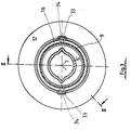
- the location of the opening 23 and the cutout 24 can best be seen from FIG. 4.
- the protective funnel 12 in addition in the direction of rotation around the longitudinal axis 7 around the connection cap 9 is set.
- the Provide connection cap 9 with two wedges 33 offset by 180 °, towards the end, i.e. towards the protective tube 8 have inclined surfaces that are easier to slide open and centering the mounting portion 16 with its grooves Allow 34.
- the wedges 33 and grooves are in the assembled state 34 but with a flat surface, so that a fuse in Direction of rotation is given.
- the protective funnel 12 is in its connection cap withdrawn in the direction of the protective tube 8 position shown so that the universal joint 2 for lubrication for example, the bearing of the cross 5 or the slide ring 10 and the sliding parts is accessible.
- the connector cap 9 meets with her Bore on the contact surface 31 of the spring bolt 22 and leaves this in a position approximated with respect to the longitudinal axis 7 spring back so that the fastening portion 16 the nose 30th can happen until the assembly position is reached and the Nose 30 again radially outwards to fix the fastening section 16 springs.
Landscapes
- Engineering & Computer Science (AREA)
- General Engineering & Computer Science (AREA)
- Mechanical Engineering (AREA)
- Motor Power Transmission Devices (AREA)
- Diaphragms And Bellows (AREA)
- Quick-Acting Or Multi-Walled Pipe Joints (AREA)
- Snaps, Bayonet Connections, Set Pins, And Snap Rings (AREA)
- Pivots And Pivotal Connections (AREA)
- Agricultural Machines (AREA)
- Sealing Devices (AREA)
- Professional, Industrial, Or Sporting Protective Garments (AREA)
Claims (11)
- Dispositif protecteur pour un arbre articulé (1), ledit arbre articulé(1) étant constitué par deux joints à croisillons (2, 2'), qui comprennent chacun deux chapes de joints (3, 4) et un croisillon (5) qui relie ces deux chapes de façon articulée, et par un arbre de liaison (6) qui comprend deux profilés coulissants (6', 6") enfilés l'un dans l'autre et reliés chacun à l'une des chapes (4) des deux joints à croisillons (2, 2'), qui comprend deux tubes protecteurs (8, 8') enfilés l'un dans l'autre et destinés à être agencés coaxialement par rapport à l'arbre de liaison (6) et à l'axe longitudinal (7) de celui-ci, avec respectivement un capuchon de raccordement (9), une bague coulissante (10) et un entonnoir protecteur (12) pour chaque joint à croisillon (2, 2'), ledit entonnoir étant destiné à recouvrir au moins partiellement axialement le joint à croisillon associé (2, 2'), dans lequel un entonnoir protecteur (12), un tube protecteur (8, 8') ainsi qu'une bague coulissante (10) sont respectivement reliés à un capuchon de raccordement (9), et la bague coulissante (10) est destinée à se loger dans une gorge (11) d'une chape de joint (4) du joint à croisillon associé (2, 2'), et l'entonnoir protecteur (12) est fixé de façon détachable sur le capuchon de raccordement (9) même lorsque le dispositif protecteur est monté sur l'arbre articulé, ledit capuchon de raccordement (9) étant pourvu d'une surface d'assise (15) sur laquelle l'entonnoir protecteur (12) peut être coiffé par un tronçon de fixation (16) et fixé au moyen d'organes de verrouillage, et détachable par intervention manuelle,
caractérisé en ce que
le tronçon de fixation (16) de l'entonnoir protecteur (12) et le capuchon de raccordement (9) comportent des moyens (33, 34) pour assurer une liaison à coopération de formes entre ces deux éléments en direction de rotation autour de l'axe longitudinal (7), lesdits moyens permettant un enfilement et un enlèvement axial, par référence à l'axe longitudinal (7), de l'entonnoir protecteur (12), en ce que le capuchon de raccordement (9) et le tronçon de fixation (16) de l'entonnoir protecteur (12) sont pourvus de butées (21, 26) pour la fixation de l'entonnoir protecteur (12) dans une direction le long de l'axe longitudinal (7) en éloignement du tube protecteur raccordé (8, 8'), et en ce qu'il est en outre prévu au moins un verrou (22) à effet élastique qui, lors de l'enfilement de l'entonnoir protecteur (12) par son tronçon de fixation (16) sur la surface d'assise (15) du capuchon de raccordement (9), est susceptible d'être passé dans une position en retrait, et après avoir atteint la position de montage des deux éléments l'un par rapport à l'autre, ledit verrou fixe le tronçon de fixation (16) en direction du tube protecteur (8, 8') au moyen d'une surface de verrouillage (28) qui attaque une contre-surface correspondante (29, 29') du tronçon de fixation (16). - Dispositif protecteur selon la revendication 1, caractérisé en ce que le verrou à effet élastique (22) est associé à la bague coulissante (10) et réalisé d'une seule pièce avec celle-ci.
- Dispositif protecteur selon l'une ou l'autre des revendications 1 et 2,
caractérisé en ce que la bague coulissante (10) est en matière plastique, en particulier en polyamide, et en ce qu'elle est associée au verrou à effet élastique (22) pour le soutien d'un ressort à lame métallique (27). - Dispositif protecteur selon l'une des revendications 1 à 3, caractérisé en ce qu'il est prévu deux verrous à effet élastique (22) décalés de 180° en sens périphérique autour de l'axe longitudinal (7).
- Dispositif protecteur selon l'une des revendications 1 à 4, caractérisé en ce que la contre-surface (29) du tronçon de fixation (16) est agencée dans une traversée radiale (23) du tronçon de fixation (16).
- Dispositif protecteur selon l'une des revendications 1 à 4, caractérisé en ce que la contre-surface (29') du tronçon de fixation (16) est agencée dans une découpe (24) du tronçon de fixation (16).
- Dispositif protecteur selon l'une ou l'autre des revendications 5 et 6,
caractérisé en ce que la surface de verrouillage (28) fait partie d'un doigt (30) dirigé vers l'extérieur en éloignement de l'axe longitudinal (7). - Dispositif protecteur selon la revendication 7, caractérisé en ce que le doigt (30) est pourvu d'une surface d'engagement (31) pour le passage du verrou (22) dans la position en retrait.
- Dispositif protecteur selon la revendication 7, caractérisé en ce que le doigt (30) comporte un renfoncement (32) pour l'engagement d'un outil.
- Dispositif protecteur selon l'une des revendications 1 à 5,
caractérisé en ce que l'entonnoir protecteur (12) est réalisé en plusieurs parties, et comprend un composant qui représente le tronçon de fixation (16) ainsi qu'un élément protecteur (17). - Dispositif protecteur selon la revendication 1, caractérisé en ce que, pour la liaison à coopération de formes entre le tronçon de fixation (16) de l'entonnoir protecteur (12) et le capuchon de raccordement (9), le capuchon de raccordement (9) est pourvu de coins (33) répartis en périphérie autour de l'axe longitudinal (7) et dépassant radialement vers l'extérieur au-delà de la surface d'assise, et le tronçon de fixation (16) de l'entonnoir protecteur (12) est pourvu de gorges (34) réalisées et réparties de façon correspondante, qui s'étendent parallèlement à l'axe longitudinal (7).
Applications Claiming Priority (2)
| Application Number | Priority Date | Filing Date | Title |
|---|---|---|---|
| DE19541511A DE19541511C1 (de) | 1995-11-08 | 1995-11-08 | Schutzvorrichtung für Gelenkwellen mit einem abnehmbaren Schutztrichter |
| DE19541511 | 1995-11-08 |
Publications (2)
| Publication Number | Publication Date |
|---|---|
| EP0773383A1 EP0773383A1 (fr) | 1997-05-14 |
| EP0773383B1 true EP0773383B1 (fr) | 2001-07-18 |
Family
ID=7776853
Family Applications (1)
| Application Number | Title | Priority Date | Filing Date |
|---|---|---|---|
| EP96116668A Expired - Lifetime EP0773383B1 (fr) | 1995-11-08 | 1996-10-26 | Dispositif de protection pour un arbre articulé avec entonnoir protecteur amovible |
Country Status (15)
| Country | Link |
|---|---|
| US (1) | US5800271A (fr) |
| EP (1) | EP0773383B1 (fr) |
| JP (1) | JP2875514B2 (fr) |
| AU (1) | AU693043B2 (fr) |
| BR (1) | BR9605482A (fr) |
| CA (1) | CA2189716C (fr) |
| CZ (1) | CZ287554B6 (fr) |
| DE (1) | DE19541511C1 (fr) |
| DK (1) | DK0773383T3 (fr) |
| ES (1) | ES2159338T3 (fr) |
| HU (1) | HU221052B1 (fr) |
| NO (1) | NO310318B1 (fr) |
| RO (1) | RO116117B1 (fr) |
| RU (1) | RU2117196C1 (fr) |
| SK (1) | SK280390B6 (fr) |
Families Citing this family (12)
| Publication number | Priority date | Publication date | Assignee | Title |
|---|---|---|---|---|
| IT1286696B1 (it) * | 1996-08-14 | 1998-07-15 | Edi Bondioli | Albero di trasmissione cardanico in specie a cannocchiale,con guaina di protezione e cuffie di protezione delle forcelle terminali |
| IT1288372B1 (it) * | 1996-11-08 | 1998-09-22 | Eurocardan S P A | Dispositivo di protezione a cuffia con ghiera con albero, in particolare albero cardanico. |
| DE19744314C2 (de) * | 1997-10-08 | 1999-09-02 | Walterscheid Gmbh Gkn | Schutzvorrichtung für eine Gelenkwelle |
| DE19744313C2 (de) * | 1997-10-08 | 1999-08-26 | Walterscheid Gmbh Gkn | Schutzvorrichtung für ein Kreuzgelank einer Gelenkwelle |
| US9005041B2 (en) * | 2013-02-08 | 2015-04-14 | Omni Usa, Inc. | Driveline shield assembly |
| ITMO20130219A1 (it) * | 2013-07-31 | 2015-02-01 | Comer Ind Spa | Dispositivo di protezione per trasmissioni cardaniche |
| RU182201U1 (ru) * | 2018-02-22 | 2018-08-07 | Открытое акционерное общество "Саратовский завод "Серп и Молот" | Карданный вал с защитным устройством подвижного шлицевого соединения |
| CN108361291A (zh) * | 2018-02-27 | 2018-08-03 | 安徽江淮汽车集团股份有限公司 | 一种传动轴与后桥输入轴连接结构 |
| CA3133937A1 (fr) * | 2019-11-07 | 2021-05-14 | Lusetti, Lea | Arbre d'entrainement avec protections d'extremite contre les accidents lubrifiees |
| IT202000014905A1 (it) * | 2020-06-22 | 2021-12-22 | Luisetti Lea | Un sistema di protezione per un albero cardanico e albero cardanico comprendente detto sistema di protezione |
| US20240196794A1 (en) * | 2022-12-14 | 2024-06-20 | Cnh Industrial America Llc | Work vehicle with flexible power take-off shield |
| US11796009B1 (en) * | 2023-01-27 | 2023-10-24 | Ryan D. Hunter | Cover for a universal joint of a driveshaft |
Family Cites Families (12)
| Publication number | Priority date | Publication date | Assignee | Title |
|---|---|---|---|---|
| DE2327482C2 (de) * | 1973-05-30 | 1974-08-08 | Jean Walterscheid Gmbh, 5204 Lohmar | Schutzvorrichtung für Gelenkwellen |
| DE3026062C2 (de) * | 1980-07-10 | 1982-05-13 | Jean Walterscheid Gmbh, 5204 Lohmar | Schutzvorrichtung für eine Gelenkwelle |
| DE3026135C1 (de) * | 1980-07-10 | 1981-10-15 | Jean Walterscheid Gmbh, 5204 Lohmar | Schutzvorrichtung fuer eine Gelenkwelle |
| IT1167912B (it) * | 1981-06-05 | 1987-05-20 | Edi Bondioli | Protezione ad elementi componibili per alberi di trasmissione cardanici |
| IT1167944B (it) * | 1981-07-14 | 1987-05-20 | Edi Bondioli | Dispositivo di protezione della forcella di estremita' di un albero cardanico di trasmissione per macchine agricole ed altro |
| DE3208541C1 (de) * | 1982-03-10 | 1983-06-01 | Jean Walterscheid Gmbh, 5204 Lohmar | Schutzvorrichtung fuer eine Gelenkwelle |
| IT1173420B (it) * | 1984-03-01 | 1987-06-24 | Benzi & Di Terlizzi Snc | Metodo di fabbricazione di un mezzo di protezione per albero di trasmissione cardanico e mezzo di protezione ottenuto col metodo |
| JPS6245427A (ja) * | 1985-08-20 | 1987-02-27 | Sankyo Alum Ind Co Ltd | 形材の接合面形成方法 |
| JPS6245427U (fr) * | 1985-09-06 | 1987-03-19 | ||
| JP2583293B2 (ja) * | 1988-09-27 | 1997-02-19 | 光洋精工株式会社 | プロペラシャフト用カバー |
| IT1241741B (it) * | 1990-06-22 | 1994-02-01 | Edi Bondioli | Protezione per alberi cardanici con mezzi per la lubrificazione |
| SE470121B (sv) * | 1992-04-24 | 1993-11-15 | Skogs Och Lantbrukshaelsan Ab | Skyddsbälg |
-
1995
- 1995-11-08 DE DE19541511A patent/DE19541511C1/de not_active Expired - Lifetime
-
1996
- 1996-10-26 EP EP96116668A patent/EP0773383B1/fr not_active Expired - Lifetime
- 1996-10-26 DK DK96116668T patent/DK0773383T3/da active
- 1996-10-26 ES ES96116668T patent/ES2159338T3/es not_active Expired - Lifetime
- 1996-10-30 AU AU70502/96A patent/AU693043B2/en not_active Ceased
- 1996-11-05 RU RU96121516A patent/RU2117196C1/ru not_active IP Right Cessation
- 1996-11-05 RO RO96-02086A patent/RO116117B1/ro unknown
- 1996-11-06 SK SK1436-96A patent/SK280390B6/sk unknown
- 1996-11-06 CA CA002189716A patent/CA2189716C/fr not_active Expired - Fee Related
- 1996-11-07 JP JP8295246A patent/JP2875514B2/ja not_active Expired - Lifetime
- 1996-11-07 HU HU9603087A patent/HU221052B1/hu not_active IP Right Cessation
- 1996-11-07 CZ CZ19963274A patent/CZ287554B6/cs not_active IP Right Cessation
- 1996-11-07 BR BR9605482A patent/BR9605482A/pt not_active IP Right Cessation
- 1996-11-07 NO NO19964711A patent/NO310318B1/no not_active IP Right Cessation
- 1996-11-08 US US08/745,792 patent/US5800271A/en not_active Expired - Lifetime
Also Published As
| Publication number | Publication date |
|---|---|
| NO964711D0 (no) | 1996-11-07 |
| NO310318B1 (no) | 2001-06-18 |
| BR9605482A (pt) | 1998-08-11 |
| JPH09170627A (ja) | 1997-06-30 |
| HUP9603087A3 (en) | 1999-11-29 |
| NO964711L (no) | 1997-05-09 |
| HU221052B1 (hu) | 2002-07-29 |
| RU2117196C1 (ru) | 1998-08-10 |
| SK280390B6 (sk) | 2000-01-18 |
| JP2875514B2 (ja) | 1999-03-31 |
| EP0773383A1 (fr) | 1997-05-14 |
| CZ287554B6 (en) | 2000-12-13 |
| RO116117B1 (ro) | 2000-10-30 |
| AU7050296A (en) | 1997-05-22 |
| DE19541511C1 (de) | 1997-04-24 |
| CZ327496A3 (en) | 1997-05-14 |
| HUP9603087A2 (en) | 1997-10-28 |
| CA2189716A1 (fr) | 1997-05-09 |
| ES2159338T3 (es) | 2001-10-01 |
| SK143696A3 (en) | 1997-09-10 |
| US5800271A (en) | 1998-09-01 |
| CA2189716C (fr) | 2000-05-02 |
| AU693043B2 (en) | 1998-06-18 |
| DK0773383T3 (da) | 2001-11-05 |
| HU9603087D0 (en) | 1996-12-30 |
Similar Documents
| Publication | Publication Date | Title |
|---|---|---|
| EP0773383B1 (fr) | Dispositif de protection pour un arbre articulé avec entonnoir protecteur amovible | |
| EP0908083B1 (fr) | Dispositif de protection pour arbre articulé | |
| EP1263632A2 (fr) | Dispositif d'essuyage | |
| EP2054263A1 (fr) | Dispositif de transmission pour un siège de véhicule | |
| DE102008028396A1 (de) | Verbindungsanordnung und Gelenkwelle hiermit | |
| DE3829749A1 (de) | Vorrichtung zum verbinden eines arbeitsgeraets mit einem traktor | |
| DE3307339C2 (de) | Selbstkuppelbare Gelenkwelle | |
| DE3438918C2 (de) | Mitnehmerverbindung zwischen Keilwellen und Keilnaben von Sicherheitslenksäulen | |
| DE3802849C1 (fr) | ||
| DE3036771C2 (fr) | ||
| DE10011821B4 (de) | Fahrzeug-Scheibenwischvorrichtung und Verfahren zum Anbau derselben | |
| DE2905363C2 (de) | Scherbolzenkupplung | |
| DE3208541C1 (de) | Schutzvorrichtung fuer eine Gelenkwelle | |
| DE2901506C2 (de) | Scherbolzenkupplung | |
| DE19918638A1 (de) | Anschlußstück für einen Bohrer zum Erzeugen von Bohrungen in Knochengewebe, Bohrer und Bohrgerät | |
| DE202019103359U1 (de) | Linearantrieb mit Kupplung | |
| DE10001270A1 (de) | Kardangelenk | |
| DE3318745C2 (de) | Hobelmaschine, insbesondere Handhobel | |
| DE19510077C1 (de) | Schutzvorrichtung für eine Gelenkwelle | |
| DE19743585C2 (de) | Vorrichtung zur Axialsicherung einer Kupplungshülse auf einer Welle | |
| EP1293693A2 (fr) | Accouplement de sécurité pour ensemble de prise de force pour des machines agricoles | |
| DE2805919C2 (de) | Lösbare Schnellkupplung zur Verbindung zweier Wellen | |
| EP0776775A1 (fr) | Palier de roue | |
| DE19653654B4 (de) | Lagerung einer Antriebsachse | |
| EP1801485A1 (fr) | Raccord multiple pour tubes ou tuyaux |
Legal Events
| Date | Code | Title | Description |
|---|---|---|---|
| PUAI | Public reference made under article 153(3) epc to a published international application that has entered the european phase |
Free format text: ORIGINAL CODE: 0009012 |
|
| 17P | Request for examination filed |
Effective date: 19970315 |
|
| AK | Designated contracting states |
Kind code of ref document: A1 Designated state(s): CH DK ES FI FR GB IT LI NL SE |
|
| GRAG | Despatch of communication of intention to grant |
Free format text: ORIGINAL CODE: EPIDOS AGRA |
|
| 17Q | First examination report despatched |
Effective date: 20000829 |
|
| GRAG | Despatch of communication of intention to grant |
Free format text: ORIGINAL CODE: EPIDOS AGRA |
|
| GRAG | Despatch of communication of intention to grant |
Free format text: ORIGINAL CODE: EPIDOS AGRA |
|
| GRAH | Despatch of communication of intention to grant a patent |
Free format text: ORIGINAL CODE: EPIDOS IGRA |
|
| GRAG | Despatch of communication of intention to grant |
Free format text: ORIGINAL CODE: EPIDOS AGRA |
|
| RBV | Designated contracting states (corrected) |
Designated state(s): CH DK ES FI FR GB IT LI NL SE |
|
| GRAH | Despatch of communication of intention to grant a patent |
Free format text: ORIGINAL CODE: EPIDOS IGRA |
|
| REG | Reference to a national code |
Ref country code: DE Ref legal event code: 8566 |
|
| GRAA | (expected) grant |
Free format text: ORIGINAL CODE: 0009210 |
|
| AK | Designated contracting states |
Kind code of ref document: B1 Designated state(s): CH DK ES FI FR GB IT LI NL SE |
|
| RTI1 | Title (correction) |
Free format text: PROTECTIVE DEVICE FOR ARTICULATED SHAFTS WITH REMOVABLE PROTECTIVE CONE |
|
| REG | Reference to a national code |
Ref country code: CH Ref legal event code: EP |
|
| REG | Reference to a national code |
Ref country code: CH Ref legal event code: NV Representative=s name: PA ALDO ROEMPLER |
|
| ITF | It: translation for a ep patent filed | ||
| GBT | Gb: translation of ep patent filed (gb section 77(6)(a)/1977) |
Effective date: 20010831 |
|
| REG | Reference to a national code |
Ref country code: ES Ref legal event code: FG2A Ref document number: 2159338 Country of ref document: ES Kind code of ref document: T3 |
|
| REG | Reference to a national code |
Ref country code: DK Ref legal event code: T3 |
|
| ET | Fr: translation filed | ||
| REG | Reference to a national code |
Ref country code: GB Ref legal event code: IF02 |
|
| PLBE | No opposition filed within time limit |
Free format text: ORIGINAL CODE: 0009261 |
|
| STAA | Information on the status of an ep patent application or granted ep patent |
Free format text: STATUS: NO OPPOSITION FILED WITHIN TIME LIMIT |
|
| 26N | No opposition filed | ||
| PGFP | Annual fee paid to national office [announced via postgrant information from national office to epo] |
Ref country code: SE Payment date: 20021023 Year of fee payment: 7 Ref country code: FI Payment date: 20021023 Year of fee payment: 7 Ref country code: CH Payment date: 20021023 Year of fee payment: 7 |
|
| PG25 | Lapsed in a contracting state [announced via postgrant information from national office to epo] |
Ref country code: FI Free format text: LAPSE BECAUSE OF NON-PAYMENT OF DUE FEES Effective date: 20031026 |
|
| PG25 | Lapsed in a contracting state [announced via postgrant information from national office to epo] |
Ref country code: SE Free format text: LAPSE BECAUSE OF NON-PAYMENT OF DUE FEES Effective date: 20031027 |
|
| PG25 | Lapsed in a contracting state [announced via postgrant information from national office to epo] |
Ref country code: LI Free format text: LAPSE BECAUSE OF NON-PAYMENT OF DUE FEES Effective date: 20031031 Ref country code: CH Free format text: LAPSE BECAUSE OF NON-PAYMENT OF DUE FEES Effective date: 20031031 |
|
| EUG | Se: european patent has lapsed | ||
| REG | Reference to a national code |
Ref country code: CH Ref legal event code: PL |
|
| PGFP | Annual fee paid to national office [announced via postgrant information from national office to epo] |
Ref country code: GB Payment date: 20051011 Year of fee payment: 10 |
|
| PGFP | Annual fee paid to national office [announced via postgrant information from national office to epo] |
Ref country code: ES Payment date: 20051014 Year of fee payment: 10 |
|
| PGFP | Annual fee paid to national office [announced via postgrant information from national office to epo] |
Ref country code: DK Payment date: 20061213 Year of fee payment: 11 |
|
| GBPC | Gb: european patent ceased through non-payment of renewal fee |
Effective date: 20061026 |
|
| PG25 | Lapsed in a contracting state [announced via postgrant information from national office to epo] |
Ref country code: GB Free format text: LAPSE BECAUSE OF NON-PAYMENT OF DUE FEES Effective date: 20061026 |
|
| REG | Reference to a national code |
Ref country code: ES Ref legal event code: FD2A Effective date: 20061027 |
|
| PG25 | Lapsed in a contracting state [announced via postgrant information from national office to epo] |
Ref country code: ES Free format text: LAPSE BECAUSE OF NON-PAYMENT OF DUE FEES Effective date: 20061027 |
|
| REG | Reference to a national code |
Ref country code: DK Ref legal event code: EBP |
|
| PG25 | Lapsed in a contracting state [announced via postgrant information from national office to epo] |
Ref country code: DK Free format text: LAPSE BECAUSE OF NON-PAYMENT OF DUE FEES Effective date: 20071031 |
|
| REG | Reference to a national code |
Ref country code: FR Ref legal event code: PLFP Year of fee payment: 20 |
|
| PGFP | Annual fee paid to national office [announced via postgrant information from national office to epo] |
Ref country code: IT Payment date: 20151026 Year of fee payment: 20 |
|
| PGFP | Annual fee paid to national office [announced via postgrant information from national office to epo] |
Ref country code: FR Payment date: 20151026 Year of fee payment: 20 Ref country code: NL Payment date: 20151026 Year of fee payment: 20 |
|
| REG | Reference to a national code |
Ref country code: NL Ref legal event code: MK Effective date: 20161025 |