EP0773438A2 - Alignement optique automatisé à l'aide d'un balayeur galvanométrique - Google Patents
Alignement optique automatisé à l'aide d'un balayeur galvanométrique Download PDFInfo
- Publication number
- EP0773438A2 EP0773438A2 EP96306071A EP96306071A EP0773438A2 EP 0773438 A2 EP0773438 A2 EP 0773438A2 EP 96306071 A EP96306071 A EP 96306071A EP 96306071 A EP96306071 A EP 96306071A EP 0773438 A2 EP0773438 A2 EP 0773438A2
- Authority
- EP
- European Patent Office
- Prior art keywords
- array
- capillary
- detector
- electromagnetic radiation
- scan
- Prior art date
- Legal status (The legal status is an assumption and is not a legal conclusion. Google has not performed a legal analysis and makes no representation as to the accuracy of the status listed.)
- Granted
Links
- 230000003287 optical effect Effects 0.000 title description 7
- 238000000034 method Methods 0.000 claims abstract description 27
- 230000005670 electromagnetic radiation Effects 0.000 claims description 58
- 230000005855 radiation Effects 0.000 claims description 30
- 238000005251 capillar electrophoresis Methods 0.000 claims description 16
- 238000001499 laser induced fluorescence spectroscopy Methods 0.000 abstract description 5
- 238000001962 electrophoresis Methods 0.000 abstract description 4
- 238000000926 separation method Methods 0.000 description 16
- 238000001228 spectrum Methods 0.000 description 13
- 238000001514 detection method Methods 0.000 description 9
- 239000000523 sample Substances 0.000 description 8
- 230000035945 sensitivity Effects 0.000 description 8
- 238000004458 analytical method Methods 0.000 description 6
- 239000000872 buffer Substances 0.000 description 5
- 229920002521 macromolecule Polymers 0.000 description 5
- VYPSYNLAJGMNEJ-UHFFFAOYSA-N Silicium dioxide Chemical compound O=[Si]=O VYPSYNLAJGMNEJ-UHFFFAOYSA-N 0.000 description 3
- 230000005284 excitation Effects 0.000 description 3
- 230000004044 response Effects 0.000 description 3
- 239000012491 analyte Substances 0.000 description 2
- 238000013480 data collection Methods 0.000 description 2
- 230000005684 electric field Effects 0.000 description 2
- 238000005516 engineering process Methods 0.000 description 2
- 239000000284 extract Substances 0.000 description 2
- 238000001917 fluorescence detection Methods 0.000 description 2
- 239000000463 material Substances 0.000 description 2
- 230000008569 process Effects 0.000 description 2
- 108091034117 Oligonucleotide Proteins 0.000 description 1
- JLCPHMBAVCMARE-UHFFFAOYSA-N [3-[[3-[[3-[[3-[[3-[[3-[[3-[[3-[[3-[[3-[[3-[[5-(2-amino-6-oxo-1H-purin-9-yl)-3-[[3-[[3-[[3-[[3-[[3-[[5-(2-amino-6-oxo-1H-purin-9-yl)-3-[[5-(2-amino-6-oxo-1H-purin-9-yl)-3-hydroxyoxolan-2-yl]methoxy-hydroxyphosphoryl]oxyoxolan-2-yl]methoxy-hydroxyphosphoryl]oxy-5-(5-methyl-2,4-dioxopyrimidin-1-yl)oxolan-2-yl]methoxy-hydroxyphosphoryl]oxy-5-(6-aminopurin-9-yl)oxolan-2-yl]methoxy-hydroxyphosphoryl]oxy-5-(6-aminopurin-9-yl)oxolan-2-yl]methoxy-hydroxyphosphoryl]oxy-5-(6-aminopurin-9-yl)oxolan-2-yl]methoxy-hydroxyphosphoryl]oxy-5-(6-aminopurin-9-yl)oxolan-2-yl]methoxy-hydroxyphosphoryl]oxyoxolan-2-yl]methoxy-hydroxyphosphoryl]oxy-5-(5-methyl-2,4-dioxopyrimidin-1-yl)oxolan-2-yl]methoxy-hydroxyphosphoryl]oxy-5-(4-amino-2-oxopyrimidin-1-yl)oxolan-2-yl]methoxy-hydroxyphosphoryl]oxy-5-(5-methyl-2,4-dioxopyrimidin-1-yl)oxolan-2-yl]methoxy-hydroxyphosphoryl]oxy-5-(5-methyl-2,4-dioxopyrimidin-1-yl)oxolan-2-yl]methoxy-hydroxyphosphoryl]oxy-5-(6-aminopurin-9-yl)oxolan-2-yl]methoxy-hydroxyphosphoryl]oxy-5-(6-aminopurin-9-yl)oxolan-2-yl]methoxy-hydroxyphosphoryl]oxy-5-(4-amino-2-oxopyrimidin-1-yl)oxolan-2-yl]methoxy-hydroxyphosphoryl]oxy-5-(4-amino-2-oxopyrimidin-1-yl)oxolan-2-yl]methoxy-hydroxyphosphoryl]oxy-5-(4-amino-2-oxopyrimidin-1-yl)oxolan-2-yl]methoxy-hydroxyphosphoryl]oxy-5-(6-aminopurin-9-yl)oxolan-2-yl]methoxy-hydroxyphosphoryl]oxy-5-(4-amino-2-oxopyrimidin-1-yl)oxolan-2-yl]methyl [5-(6-aminopurin-9-yl)-2-(hydroxymethyl)oxolan-3-yl] hydrogen phosphate Polymers Cc1cn(C2CC(OP(O)(=O)OCC3OC(CC3OP(O)(=O)OCC3OC(CC3O)n3cnc4c3nc(N)[nH]c4=O)n3cnc4c3nc(N)[nH]c4=O)C(COP(O)(=O)OC3CC(OC3COP(O)(=O)OC3CC(OC3COP(O)(=O)OC3CC(OC3COP(O)(=O)OC3CC(OC3COP(O)(=O)OC3CC(OC3COP(O)(=O)OC3CC(OC3COP(O)(=O)OC3CC(OC3COP(O)(=O)OC3CC(OC3COP(O)(=O)OC3CC(OC3COP(O)(=O)OC3CC(OC3COP(O)(=O)OC3CC(OC3COP(O)(=O)OC3CC(OC3COP(O)(=O)OC3CC(OC3COP(O)(=O)OC3CC(OC3COP(O)(=O)OC3CC(OC3COP(O)(=O)OC3CC(OC3COP(O)(=O)OC3CC(OC3CO)n3cnc4c(N)ncnc34)n3ccc(N)nc3=O)n3cnc4c(N)ncnc34)n3ccc(N)nc3=O)n3ccc(N)nc3=O)n3ccc(N)nc3=O)n3cnc4c(N)ncnc34)n3cnc4c(N)ncnc34)n3cc(C)c(=O)[nH]c3=O)n3cc(C)c(=O)[nH]c3=O)n3ccc(N)nc3=O)n3cc(C)c(=O)[nH]c3=O)n3cnc4c3nc(N)[nH]c4=O)n3cnc4c(N)ncnc34)n3cnc4c(N)ncnc34)n3cnc4c(N)ncnc34)n3cnc4c(N)ncnc34)O2)c(=O)[nH]c1=O JLCPHMBAVCMARE-UHFFFAOYSA-N 0.000 description 1
- 238000002835 absorbance Methods 0.000 description 1
- 239000000538 analytical sample Substances 0.000 description 1
- 238000003556 assay Methods 0.000 description 1
- 230000005540 biological transmission Effects 0.000 description 1
- 230000008859 change Effects 0.000 description 1
- 150000001875 compounds Chemical class 0.000 description 1
- 230000008878 coupling Effects 0.000 description 1
- 238000010168 coupling process Methods 0.000 description 1
- 238000005859 coupling reaction Methods 0.000 description 1
- 238000013500 data storage Methods 0.000 description 1
- 239000006185 dispersion Substances 0.000 description 1
- 230000002349 favourable effect Effects 0.000 description 1
- 239000005350 fused silica glass Substances 0.000 description 1
- 238000001502 gel electrophoresis Methods 0.000 description 1
- 238000005286 illumination Methods 0.000 description 1
- 230000003993 interaction Effects 0.000 description 1
- 238000013507 mapping Methods 0.000 description 1
- 230000004048 modification Effects 0.000 description 1
- 238000012986 modification Methods 0.000 description 1
- 108020004707 nucleic acids Proteins 0.000 description 1
- 102000039446 nucleic acids Human genes 0.000 description 1
- 150000007523 nucleic acids Chemical class 0.000 description 1
- 229920002401 polyacrylamide Polymers 0.000 description 1
- 102000004196 processed proteins & peptides Human genes 0.000 description 1
- 108090000765 processed proteins & peptides Proteins 0.000 description 1
- 102000004169 proteins and genes Human genes 0.000 description 1
- 108090000623 proteins and genes Proteins 0.000 description 1
- 238000004445 quantitative analysis Methods 0.000 description 1
- 239000000377 silicon dioxide Substances 0.000 description 1
- 239000000758 substrate Substances 0.000 description 1
Images





Classifications
-
- G—PHYSICS
- G01—MEASURING; TESTING
- G01N—INVESTIGATING OR ANALYSING MATERIALS BY DETERMINING THEIR CHEMICAL OR PHYSICAL PROPERTIES
- G01N27/00—Investigating or analysing materials by the use of electric, electrochemical, or magnetic means
- G01N27/26—Investigating or analysing materials by the use of electric, electrochemical, or magnetic means by investigating electrochemical variables; by using electrolysis or electrophoresis
- G01N27/416—Systems
- G01N27/447—Systems using electrophoresis
- G01N27/44704—Details; Accessories
- G01N27/44717—Arrangements for investigating the separated zones, e.g. localising zones
- G01N27/44721—Arrangements for investigating the separated zones, e.g. localising zones by optical means
-
- G—PHYSICS
- G01—MEASURING; TESTING
- G01N—INVESTIGATING OR ANALYSING MATERIALS BY DETERMINING THEIR CHEMICAL OR PHYSICAL PROPERTIES
- G01N21/00—Investigating or analysing materials by the use of optical means, i.e. using sub-millimetre waves, infrared, visible or ultraviolet light
- G01N21/62—Systems in which the material investigated is excited whereby it emits light or causes a change in wavelength of the incident light
- G01N21/63—Systems in which the material investigated is excited whereby it emits light or causes a change in wavelength of the incident light optically excited
- G01N21/64—Fluorescence; Phosphorescence
- G01N21/6402—Atomic fluorescence; Laser induced fluorescence
-
- G—PHYSICS
- G01—MEASURING; TESTING
- G01N—INVESTIGATING OR ANALYSING MATERIALS BY DETERMINING THEIR CHEMICAL OR PHYSICAL PROPERTIES
- G01N21/00—Investigating or analysing materials by the use of optical means, i.e. using sub-millimetre waves, infrared, visible or ultraviolet light
- G01N21/62—Systems in which the material investigated is excited whereby it emits light or causes a change in wavelength of the incident light
- G01N21/63—Systems in which the material investigated is excited whereby it emits light or causes a change in wavelength of the incident light optically excited
- G01N21/64—Fluorescence; Phosphorescence
- G01N21/6428—Measuring fluorescence of fluorescent products of reactions or of fluorochrome labelled reactive substances, e.g. measuring quenching effects, using measuring "optrodes"
-
- G—PHYSICS
- G01—MEASURING; TESTING
- G01N—INVESTIGATING OR ANALYSING MATERIALS BY DETERMINING THEIR CHEMICAL OR PHYSICAL PROPERTIES
- G01N21/00—Investigating or analysing materials by the use of optical means, i.e. using sub-millimetre waves, infrared, visible or ultraviolet light
- G01N21/62—Systems in which the material investigated is excited whereby it emits light or causes a change in wavelength of the incident light
- G01N21/63—Systems in which the material investigated is excited whereby it emits light or causes a change in wavelength of the incident light optically excited
- G01N21/64—Fluorescence; Phosphorescence
- G01N21/645—Specially adapted constructive features of fluorimeters
- G01N21/6452—Individual samples arranged in a regular 2D-array, e.g. multiwell plates
Definitions
- the present invention relates generally to optical detection systems for use in multicapillary analytical instrumentation. More particularly, the present invention involves apparatus and methods for automatically aligning an electromagnetic beam with the centers of each of a plurality of capillaries which collectively form a capillary array.
- Electrophoretic separation techniques have been utilized for decades to separate molecules according to differences in the effective charge of the molecules, and/or according to differences in the molecular size of the molecules. Up until recently electrophoretic separations were conducted in gel slabs or open gel beds which were typically fabricated of polyacrylamide gel material. More recently capillary electrophoresis techniques combined with photometric detection methods have allowed the automation and rapid quantitative analysis of molecules. High resolution separations of molecules having different effective charges have been achieved by applying electrophoretic principles to buffer filled or gel filled narrow capillary tubes.
- capillary columns used in capillary electrophoresis are fabricated of lengths of silica tubing having diameters on the order of 25 ⁇ m to 200 ⁇ m and lengths from about 10 to 200 cm.
- the buffer and gel separation mediums are pumped directly into the column interiors, analytical samples are moved into one end of the column, and an electric field is applied to the column.
- Charged species within the column migrate under the influence of the electric field, at a rate which depends upon their electrophoretic mobility.
- Capillary electrophoresis is used to separate numerous types of molecules including peptides, proteins, and oligonucleotides, nucleic acids and other charged molecular species.
- the field of electrophoretic separation technology is continually expanding with respect to the types and sizes of molecules which can be separated and detected using capillary electrophoresis procedures.
- the ability to align accurately a source beam with respect to the center of each capillary improves performance of the system.
- the ability to rapidly and automatically align a focused source beam position with respect to the center of each capillary prior to each electrophoretic run in a pre-scan alignment step is highly desirable.
- the present invention provides apparatus and methods for automatically aligning a focused source beam with the center of each capillary in a multicapillary electrophoresis system.
- Such automatic alignment apparatus and methods allow users to change capillaries and be assured of repeated sensitivity and precision in their multicapillary assays.
- an automated optical alignment apparatus and method which, through an alignment sequence, determines the centers of each of a plurality of capillary columns configured in a ribbon like array.
- at least one source of electromagnetic radiation preferably a laser
- a galvometric scanner moves a mirror in very small step increments, causing a electromagnetic radiation laser beam to scan across the capillaries in the capillary array.
- the beam interacts with each of the capillary columns to provide a variable intensity light pattern of transmitted and dispersed radiation.
- an appropriately positioned detector monitors the transmitted beam intensity as a function of the mirror position.
- a processor extracts radiation intensities indicative of the beam striking the center of the columns and determines the mirror positions corresponding to these capillary centers.
- the positions of the scanner mirror corresponding with the beam striking each column center are selected and stored. Thereafter, since the pre-scan has optically aligned the electromagnetic source with the centers of the columns, the processor controls the scanning mirror to step-scan very rapidly the beam from column center-to-center. In this fashion, the time spend illuminating each capillary at off-center positions is minimized, thereby optimizing the duty cycle and providing maximum sensitivity.
- the methods and apparatus of the present invention provide increased sensitivity for both excitation and emission.
- one aspect of the present invention provides an apparatus for aligning each of a plurality of columns in an array comprising:
- Said directing means may be capable of positional changes in order to sequentially scan each of said capillaries to provide said variable intensity radiation patterns.
- the apparatus may further include a sensor means for sensing the position of said directing means during said scan and a processor means for comparing the position of said directing means to the detected radiation pattern to determine the positions of the directing means corresponding to the directing means directing electromagnetic radiation to the column centers.
- Said directing means may be a reflector.
- the directing means may direct the electromagnetic radiation along an axis path to the array, the detector being disposed along said axis path and past array.
- the directing means may direct the electromagnetic radiation along an axis path to the array, the detector disposed at a position offset from said axis path and past said array.
- the directing means may be a mirror mounted on a galvometric scanner.
- the generating means may be a laser.
- an apparatus for determining the center positions for each column of an array for electromagnetic radiation interrogation comprising:
- the electromagnetic radiation source may be a laser.
- an apparatus for capillary electrophoresis, induced fluorescence sample interrogation in a multicapillary array comprising:
- the intensity pattern detector may be a photodiode.
- An axis may be defined by the beam reflected by the reflector to the center of the array, the intensity pattern detector being disposed on the axis behind the array.
- An axis may be defined by the beam reflected by the reflector to the center of the array, the intensity pattern detector being disposed in a position spaced from the axis.
- a method for determining the center for each capillary of an array comprising:
- an apparatus for aligning each of a plurality of columns in an array comprising:
- the present invention is directed to automated optical alignment apparatus and methods for their use in multicapillary electrophoretic separation systems.
- the invention described herein is suitable for use in systems having optically based detection including, but not limited to, fluorescence, uv-visible, refractive index, thermooptical absorbance, and degenerate four wave mapping.
- fluorescence detection is typically the method of choice for achieving high sensitivity detection following capillary electrophoresis separation
- the preferred embodiment utilizes a laser source and fluorescence detection (CE-LIF).
- CE-LIF laser source and fluorescence detection
- the apparatus and method according to the present invention is adapted to be used with a CE-LIF system 10, shown generally in Fig. 1 and which is described in pending U.S. Patent application Ser. No. 08/429,406 the description of which is incorporated by reference for background purposes.
- the CE-LIF system 10 requires directing interrogating electromagnetic radiation to each sample volume contained in each capillary column 11 in a multi-capillary array 12.
- the interrogation is performed sequentially and repetitively, however, in practice, the apparatus and method is versatile and any single capillary in any order may be interrogated.
- Macromolecules tagged with fluorescent tags fluoresce when excited by the interrogating electromagnetic radiation. That fluorescence is collected and detected to determine the presence, concentration and location of the tagged macromolecules.
- the CE-LIF system 10 includes at least one, and may include several, sources of electromagnetic radiation shown for purposes of illustration as a pair of lasers 14 A, B.
- Laser 14A may be a diode laser emitting a wavelength of a 655 nm whereas laser 14B may have a wavelength of a 755 nm.
- a plurality of sources of electromagnetic radiation may be used to direct a variety of wavelengths for excitation of appropriately tagged macromolecule in each capillary column 11.
- the output of the lasers 14A, 14B are passed through line filters 16A, 16B to a beam combiner 18, such as a dichroic mirror, which acts to direct beams 20 from the lasers 14A, 14B along a common optical path A.
- system 10 includes a galvometric scanner 22 which includes a reflector such as a mirror 23.
- the scanner 22 is of the type manufactured by General Scanning of California. Scanner 22 is a precision, highspeed, electro-mechanical device that has a fast dynamic response because of its favorable torque-to-inertia ratio. Applying a scanning voltage to the scanner 22 causes the mirror 23 to move to reflect the beam 20 to scan, as described below, across capillary array 12.
- reflected beam 20 illuminates or interrogates each capillary and excites appropriately fluorescing compounds to emit fluorescent radiation.
- a pair of electromagnetic sources lasers 14A and 14B, are shown in Fig. 1, the interrogation of each capillary column of array 12 preferably occurs with first one wavelength, i.e., the beam emitted from laser 14A for all capillary columns and, thereafter, the same interrogation occurs with the reflected beam emitted from laser 14B.
- all the interrogating wavelengths can be handled in a single scan.
- the CE-LIF system 10 includes a high collection efficiency parabolic collector 28.
- Capillary array 12, as illustrated in Fig. 1 is positioned about the focal point of the collector 28.
- the interrogating beams are directed by the focusing lens 26 through an aperture (not shown) in a side of collector 28.
- Fluorescent emission, shown as rays 30 from each capillary column interrogated, is collected by the collector 28 and directed to the detector 26 which is a photomultiplier tube or other suitable detector.
- a scatterbar 32 may be positioned in a plane orthogonal to the axis of the array 12 to obstruct intense laser scatter light surrounding the columns 11 in this plane.
- One or more filters 34 may also be selectively positioned to block any scatter or background excitation radiation from the source and to allow transmission of selected emission fluorescence from the excited samples in the capillary columns 11.
- a detector lens 35 focuses the rays 32 to the detector 26.
- the detector 26 provides a signal in response to the presence of the emitted rays 30 to a processor shown generally as 36 for determination of the presence and concentration of the corresponding tagged macromolecule.
- array 12 includes 8 co-planer, parallel-arranged capillary columns 11 positioned side by side. It should be understood that any number of columns 11, such as twelve, may be provided on the array 12.
- the capillary columns 11 are fabricated of fused silica and have dimensions which can vary with the particular application. Suitable capillary dimensions can be typical of those utilized in capillary electrophoresis methods and include lengths of between 20 cm and 500 cm, and diameters of between 20 ⁇ m and 500 ⁇ m. Preferably, capillaries have relatively large wall thicknesses of approximately 50 ⁇ m.
- Columns 11 are manually glued together on an array substrate in order to secure the column position.
- a capillary outer diameter of 200 ⁇ m and an inner diameter of 100 ⁇ m will be referred to for purposes of discussion unless otherwise indicated.
- the array 12 is positioned so that the focused beam 20 is perpendicular to the longitudinal axes of the cylindrical columns 11.
- array 12 is removable and interchangeably held in the capillary electrophoresis system 10 by a holding fixture (not shown).
- a high voltage power supply is coupled to array 12 and each column 11 as is a manifold (also not shown).
- the manifold supplies separation medium which can include gel and/or buffers under high pressure to each of the capillary columns 11.
- the present invention is provided to locate and optically align the interrogating beam with each of the column centers of the columns of array 12.
- the present invention is based upon the observation that, as a reflected beam is scanned across an array of capillaries, a variable intensity light pattern is observed at a location behind the array.
- the intensity variation of the pattern, as a beam is scanned across the array can be used to determine the positions of the centers of the capillary columns.
- Apparatus 100 includes detector 112a (or 112b) disposed behind a capillary array 114 for detecting variable intensity patterns 116 of electromagnetic radiation produced during a scan of reflected beam 110 across array 114.
- Detector 112a and 112b can be any type suitable for detected electromagnetic radiation within the wavelength range of the transmitted beam. Photodiodes are preferred for their simplicity and ease in handling.
- detector 112a and 112b may be disposed on-axis 120 (as indicated by the position of detector 112a) or in a position off-axis 120 (as indicated by the position of detector 112b). As discussed below, preferably, the detector is positioned in a position behind the array 114 and off-axis 120 to provide best results. In most preferred embodiments, detector 112b is 130 mm behind capillary array 114 and 20 mm off-axis 120.
- a galvometric scanner 122 and associated scanner mirror 122a mounted on scanner 122 is controlled by a processor (not shown) which applies a string of voltages to the scanner 122.
- the string of applied voltages causes the scanner mirror to move in rapid, very small incremental steps and to reflect beam 110 in a manner that causes the beam to pass through focusing lens 150 and sweep back and forth across capillary array 114.
- a position sensor for the scanner mirror 122a e.g. a capacitance position sensor, sends signals to a scanner controller corresponding to the position of mirror 122a.
- Mirror 122a position signal corresponds to each incremental position of the beam 110 on the array 114.
- a 1.8mV step in voltage to the scanner 122 results in a discrete step in resulting beam position at the 114.
- the 1.8mV step to scanner 122 is equal to a 7.7 ⁇ m + 0.6 ⁇ m step at the array 114.
- scanner 122 can be caused to move scanner mirror 122a by issuing a string of step voltages in rapid sequence, or scanner 122 can be positioned at discrete locations on the array 114 by the application of the appropriate voltage.
- a typical electromagnetic radiation variable intensity pattern formed as reflected beam 110 is swept across a single capillary column of array 114.
- the variable intensity pattern is illustrated for the on-axis detector 112a and off-axis detector 112b positions.
- the electromagnetic radiation is passed as a maximum intensity beam.
- a lower intensity, diffuse pattern is presented which grows with intensity as the beam processes to the center of the capillary column.
- the pattern of the transmitted light intensity is symmetrical, with intensity being great in the middle and diffusing at the edges. Moving from the column center position, the intensity falls as the radiation is diffusely transmitted by the capillary wall.
- the beam sweeps to a location between the capillary and its adjacent capillary and is detected as another maximum intensity, tightly focused beam.
- the detected electromagnetic radiation produces a variable intensity spectrum which can advantageously be used to determine the position of the scanner 122 corresponding to reflecting beam 110 on each capillary center. Because each scanner position has a unique applied voltage value, by correlating the applied voltage corresponding to the radiation pattern associated with each column center, scanner mirror positions for each column center can be determined.
- on-axis detector 112a observes a highly intense narrow signal when the beam misses a capillary, either because it misses the array or is in between capillaries.
- Detector 112a observes a weak broad diffuse signal when the beam hits a capillary wall and a bright spot which traverses across the broad dispersion pattern as the beam scans across the center of the capillary.
- the detector is off-axis (detector 112b) and positioned 20 mm to the side of laser axis 120.
- off-axis detector 112b observes slightly different patterns compared with those detected by on-axis detector 112a.
- Detector 112b detects no light when the laser misses a capillary but detects an intense light spot when the beam scans through the capillary center.
- off-axis detector 112b is positioned to provide an enhanced sensitivity to the column center determination process.
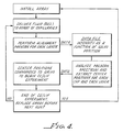
- the method for determining the scanner 122 positions which correspond to the center of each capillary column array 114 includes sequences diagramed in Fig. 4.
- a processor initiates a pre-scan step for laser N 1 , for example, laser source 126a.
- a sequence is initiated which issues a voltage to the scanner 122 to position the mirror 122a at an end position.
- a rapid string of voltages is issued to the scanner 122 to rapidly step the scanner mirror 122a to scan reflected beam 110 back and forth across the array 114.
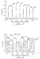
- Fig. 5 is a spectrum of the intensity pattern observed by on-axis detector 112a as beam 110 scans back and forth across each capillary of array 114.
- Fig. 7 is a similar spectrum of the intensity pattern observed by off-axis detector 112b as beam 120 scans across each capillary of array 114. Signals corresponding to the intensities detected by the detector 112a are sent to the processor. As stated above, each step of the scanner 122 corresponds to a voltage input of 1.8 mV and 7.7 +/- 0.6 microns. A data file is generated with detector signal intensity as a function of galvo scanner or mirror position.
- a processor analyzes the data and extracts the positions of the scanner mirror 122a which correspond to those voltage intensities detected by detector 112a which are indicative of the centers of the capillary columns. This center position data is used then in subsequent data collection during electrophoresis runs. At the end of the alignment scan for laser 126a the same alignment pre-scan is initiated and carried out for laser 126b and thereafter for any additional sources.
- the electromagnetic radiation intensity pattern versus scanner 122 position for an array having eight capillary columns (a - h) is shown as detected by on-axis detector 112a positioned behind the array 114.
- the pattern includes maxima 58 a-h corresponding to the positions of the scanner mirror 122a when the reflected beam 110 strikes the center of each column.
- the end portions 60 of the Fig. 5 spectrum illustrate where the beam misses the array entirely, whereas the intermediate peaks between the maxima 58 a-h for the columns 11 indicate the strong signal received when the beam illuminates the area between capillaries.
- Fig. 6 provides an enlarged portion of Fig. 5 corresponding to the radiation intensity pattern obtained while scanning across capillary h.
- the electromagnetic radiation intensity pattern versus scanner 122 position for an array having eight capillary columns (a - h) is shown as detected by off-axis detector 112b positioned behind the array 114.
- the transmitted electromagnetic radiation intensity pattern produced during the scan produces eight discrete maxima 62 a-h, indicative of beam positions which are slightly off column center and in the column bore of the 8 columns (a - h).
- the peaks observed by the off-axis detector 112b do not reach a maxima until several steps after the on-axis detector registers a capillary center.
- the capillary centers observed by on-axis detector 112a generally are four steps off from the maxima observed by detector 112b, whose detected maxima is shown by the dashed lines.
- the number of mirror positions or galvoscanner steps required to scan across a single capillary, and therefore, the distance scanned in moving the mirror one step is known. More particularly, 26 steps of 1.8 mV/step are required to scan the galvoscanner mirror across one capillary.
- a single capillary is 200 ⁇ m wide, so a 1.8 mV step is equal to 7.7 +/- 0.6 ⁇ m.
- a two step offset is in the vicinity of 15.5 microns and four step offset is about 31 ⁇ m.
- the intensity patterns observed by off-axis detector 112b provide more discrete maxima intensities (and thus a more simple spectrum) for capillary column center determination. Accordingly, in preferred embodiments the detector is positioned off-axis. Even though the 20 mm off-axis position is preferred, those skilled in the art will recognize that any suitable detector, positioned to detect any portion of the dispersed and transmitted electromagnetic radiation as the scan mirror directs a beam across an array can be used in the practice of the present invention.
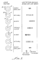
- Fig. 9 illustrates this concept by tabulating the number of galvoscanner steps offset from each actual capillary center as observed for a number of different off-axis detector positions.
- the offset from true center is four steps or about 31 ⁇ m.
- the offset increases as shown by the offsets associated with a detector positioned 25 mm off-axis. It is evident from the information provided in Fig. 9 that capillary inner and outer diameters vary, causing a variation in the offset.
- the multicapillary system of Fig. 1 is ready to perform analytical procedures as described above. That is, each of the focused source beams is directed to the pre-scan determined centers of each of the capillary columns of the array 12 in order to provide electromagnetic radiation for interaction with sample in the capillaries.
- the scanner 22 may hold its position for a pre-set time, for example, 15.7 msec, and thereafter rapidly index in response to positioning voltage to direct the beam 20 to the next column center.
- the focus beam 20 will be stepped rapidly between each capillary 11 center with a resultant highly efficient sample illumination and interrogation.
- This duty cycle involves holding the beam at each capillary center for pre-set intervals. For example, if eight capillaries are to be monitored at an effective scan rate of 2 Hz, the time to step 200 ⁇ m (capillary center-to-center for 100/200 capillaries) is 400 ⁇ sec, and the return scan time is 1 msec, then 99.24% of the total scan time is available as dwell-time when data collection takes place at capillary centers.
- a secondary mirror 130 is used to reflect the electromagnetic intensity patterns to a detector 140a and 140b.
- the detector may be disposed in the path of the reflected axis, detector 140a, or off-axis, detector 140b to obtain the intensity patterns referred to above.
- This embodiment would permit placement of the detector in a suitable location should the configuration shown in Fig. 1 not be possible due to size or equipment placement constraints.
- the apparatus and methods of the present invention typically will be utilized in a pre-scan alignment for subsequent analysis using the system shown in Fig.
- the automatic alignment apparatus of method of the present invention has utility at any time and is not limited to pre-scans.
- an alignment can be initiated to confirm alignment, even though an analysis may not be performed immediately after exchanging the gel.
- the above-described aspects of the present invention are directed toward a side-by-side alignment of each capillary within an array of capillary or a horizontal capillary alignment.
- a vertical alignment, or the alignment of the optical path of the laser beam 310, the focal plane of the collection parabola 380, the capillary windows (not shown) of the capillaries of array, and the photomultiplier tube detector 330 More particularly, the height of the focusing lens 340 which focuses the laser beam 310 to the capillaries, the height of the photomultiplier tube detector 330, the height of the focal plane of the parabola 380 and the height of the capillary windows can be aligned with respect to one another so that they are all on the same vertical plane.
- slit 350a in front of on-axis detector 360a or slit 350b in front of off-axis detector 360b Laser radiation from source 370a or 370b is directed off scanner mirror 390 through focusing lens 340 and capillary array 320. After passing through array 320 the beam is reflected to either detector 360a or 360b through associated slit 350a or 350b. If the pattern detected by detector 360a or 360b indicates a slit configuration as shown in the side view of Fig. 11b, then the system is vertically aligned. If the configuration is not clear, focusing lens 340 is moved using motor control 370 in order to appropriately focus the beam on array 320 at the focal plane of parabola 380. The lens is adjusted until the appropriate vertical height is met.
Landscapes
- Health & Medical Sciences (AREA)
- Life Sciences & Earth Sciences (AREA)
- Chemical & Material Sciences (AREA)
- Physics & Mathematics (AREA)
- Immunology (AREA)
- Analytical Chemistry (AREA)
- Biochemistry (AREA)
- General Health & Medical Sciences (AREA)
- General Physics & Mathematics (AREA)
- Pathology (AREA)
- Nuclear Medicine, Radiotherapy & Molecular Imaging (AREA)
- Optics & Photonics (AREA)
- Chemical Kinetics & Catalysis (AREA)
- Molecular Biology (AREA)
- Electrochemistry (AREA)
- Investigating, Analyzing Materials By Fluorescence Or Luminescence (AREA)
- Investigating Or Analysing Materials By Optical Means (AREA)
- Length Measuring Devices By Optical Means (AREA)
Priority Applications (1)
| Application Number | Priority Date | Filing Date | Title |
|---|---|---|---|
| EP04075245A EP1431748A3 (fr) | 1995-08-23 | 1996-08-20 | Alignement optique automatisé à l'aide d'un balayeur galvanométrique |
Applications Claiming Priority (2)
| Application Number | Priority Date | Filing Date | Title |
|---|---|---|---|
| US08/518,283 US5545901A (en) | 1995-08-23 | 1995-08-23 | Automated optical alignment using a galvometric scanner |
| US518283 | 1995-08-23 |
Related Child Applications (1)
| Application Number | Title | Priority Date | Filing Date |
|---|---|---|---|
| EP04075245A Division EP1431748A3 (fr) | 1995-08-23 | 1996-08-20 | Alignement optique automatisé à l'aide d'un balayeur galvanométrique |
Publications (3)
| Publication Number | Publication Date |
|---|---|
| EP0773438A2 true EP0773438A2 (fr) | 1997-05-14 |
| EP0773438A3 EP0773438A3 (fr) | 1997-07-23 |
| EP0773438B1 EP0773438B1 (fr) | 2005-10-19 |
Family
ID=24063311
Family Applications (2)
| Application Number | Title | Priority Date | Filing Date |
|---|---|---|---|
| EP04075245A Ceased EP1431748A3 (fr) | 1995-08-23 | 1996-08-20 | Alignement optique automatisé à l'aide d'un balayeur galvanométrique |
| EP96306071A Expired - Lifetime EP0773438B1 (fr) | 1995-08-23 | 1996-08-20 | Alignement optique automatisé à l'aide d'un balayeur galvanométrique |
Family Applications Before (1)
| Application Number | Title | Priority Date | Filing Date |
|---|---|---|---|
| EP04075245A Ceased EP1431748A3 (fr) | 1995-08-23 | 1996-08-20 | Alignement optique automatisé à l'aide d'un balayeur galvanométrique |
Country Status (4)
| Country | Link |
|---|---|
| US (1) | US5545901A (fr) |
| EP (2) | EP1431748A3 (fr) |
| JP (3) | JPH09119809A (fr) |
| DE (1) | DE69635296T2 (fr) |
Families Citing this family (17)
| Publication number | Priority date | Publication date | Assignee | Title |
|---|---|---|---|---|
| US5545901A (en) * | 1995-08-23 | 1996-08-13 | Beckman Instruments, Inc. | Automated optical alignment using a galvometric scanner |
| US6225635B1 (en) * | 1998-08-07 | 2001-05-01 | The Regents Of The University Of California | System and method for optically locating microchannel positions |
| JP3613032B2 (ja) * | 1998-10-26 | 2005-01-26 | 株式会社日立製作所 | キャピラリーアレイ電気泳動装置 |
| US6246046B1 (en) | 1999-01-21 | 2001-06-12 | University Of Pittsburgh | Method and apparatus for electronically controlled scanning of micro-area devices |
| US6768812B1 (en) * | 1999-05-27 | 2004-07-27 | Cognex Corporation | Method for locating features on an object using varied illumination |
| US6592733B1 (en) | 1999-11-12 | 2003-07-15 | Motorola, Inc. | Capillary electrophoresis devices incorporating optical waveguides |
| US6932940B2 (en) * | 2001-06-22 | 2005-08-23 | Biocal Technology, Inc. | Optical detection in bio-separation device using axial radiation input |
| AU2002310510A1 (en) * | 2001-06-22 | 2003-01-08 | Biocal Technology, Inc. | Optical detection in bio-separation device having axial radiation input and output and widened detection zone |
| US6929779B2 (en) | 2001-06-22 | 2005-08-16 | Biocal Technology, Inc. | Optical detection in bio-separation device using axial radiation output |
| AU2002357368A1 (en) * | 2001-12-19 | 2003-07-09 | Affymetrix, Inc. | Array plates and method for constructing array plates |
| JP3761475B2 (ja) * | 2002-02-28 | 2006-03-29 | 国際技術開発株式会社 | 試料カートリッジ及び試料分析装置 |
| US6770892B2 (en) * | 2002-02-28 | 2004-08-03 | Agilent Technologies, Inc. | Method and system for automated focus-distance determination for molecular array scanners |
| AU2011203525B8 (en) * | 2005-05-19 | 2014-03-06 | Ande Corporation | An apparatus for analyzing/processing a sample of biomolecular analyte, device and method |
| US8206974B2 (en) * | 2005-05-19 | 2012-06-26 | Netbio, Inc. | Ruggedized apparatus for analysis of nucleic acid and proteins |
| JP4909744B2 (ja) * | 2006-01-16 | 2012-04-04 | 株式会社日立ハイテクノロジーズ | キャピラリ電気泳動装置及び電気泳動方法 |
| CA3106132C (fr) | 2011-05-12 | 2023-08-29 | Ande Corporation | Procedes et compositions destines a l'amplification multiplex rapide de loci de sequences courtes repetees en tandem |
| WO2021095006A1 (fr) | 2019-11-14 | 2021-05-20 | Dh Technologies Development Pte. Ltd. | Système optique de balayage à double mode pour électrophorèse capillaire |
Family Cites Families (17)
| Publication number | Priority date | Publication date | Assignee | Title |
|---|---|---|---|---|
| SE8102772L (sv) * | 1981-05-04 | 1982-11-05 | Sven Staffan Folestad | Forfarande for laserinducerad fluoriscensdetektering och anordning for genomforande av forfarandet |
| US4648715A (en) * | 1982-09-07 | 1987-03-10 | Langley-Ford Instruments A Division Of Coulter Electronics Of N.E. | Electrophoretic light scattering with plural reference beams, apparatus and method |
| JPH0638064B2 (ja) * | 1985-01-19 | 1994-05-18 | キヤノン株式会社 | 粒子解析装置 |
| JPS628038A (ja) * | 1985-07-05 | 1987-01-16 | Canon Inc | 粒子解析装置 |
| US4837446A (en) * | 1988-03-31 | 1989-06-06 | International Paper Company | Apparatus and process for testing uniformity of pulp |
| JP2745568B2 (ja) * | 1988-09-30 | 1998-04-28 | 株式会社島津製作所 | キャピラリセル検出器の調整方法及び調整機構 |
| JPH02218941A (ja) * | 1989-02-18 | 1990-08-31 | Shimadzu Corp | 蛍光検出型ゲル電気泳動パターン解析装置 |
| US5274240A (en) * | 1990-01-12 | 1993-12-28 | The Regents Of The University Of California | Capillary array confocal fluorescence scanner and method |
| JP2873884B2 (ja) * | 1991-03-22 | 1999-03-24 | 日立ソフトウェアエンジニアリング 株式会社 | 多色泳動パターン読み取り装置 |
| DE69221423T2 (de) * | 1991-09-30 | 1998-03-19 | Beckman Instruments Inc | Verbesserte Fluoreszenz-Erfassung von Proben in einem Kapillarrohr |
| US5208466A (en) * | 1991-10-08 | 1993-05-04 | Beckman Instruments, Inc. | Apparatus and method for aligning capillary column and detection optics |
| JP2640704B2 (ja) * | 1991-12-30 | 1997-08-13 | 日立ソフトウエアエンジニアリング株式会社 | 蛍光パターン読み取り装置 |
| WO1993019205A1 (fr) * | 1992-03-19 | 1993-09-30 | The Regents Of The University Of California | Procede de marquage a plusieurs etiquettes permettant d'effectuer le sequencage de l'adn |
| EP0654090A4 (fr) * | 1992-08-10 | 1998-07-08 | Biometric Imaging Inc | Procede de detection par separation differentielle et equipements de test. |
| US5371016A (en) * | 1993-04-26 | 1994-12-06 | Becton, Dickinson And Company | Detecting biological activities in culture vials |
| US5483075A (en) * | 1994-11-01 | 1996-01-09 | Perkin-Elmer Corporation | Rotary scanning apparatus |
| US5545901A (en) * | 1995-08-23 | 1996-08-13 | Beckman Instruments, Inc. | Automated optical alignment using a galvometric scanner |
-
1995
- 1995-08-23 US US08/518,283 patent/US5545901A/en not_active Expired - Lifetime
-
1996
- 1996-08-20 DE DE69635296T patent/DE69635296T2/de not_active Expired - Lifetime
- 1996-08-20 EP EP04075245A patent/EP1431748A3/fr not_active Ceased
- 1996-08-20 EP EP96306071A patent/EP0773438B1/fr not_active Expired - Lifetime
- 1996-08-23 JP JP8240021A patent/JPH09119809A/ja active Pending
-
2006
- 2006-03-15 JP JP2006070876A patent/JP4463228B2/ja not_active Expired - Lifetime
-
2009
- 2009-10-15 JP JP2009238100A patent/JP5145309B2/ja not_active Expired - Lifetime
Also Published As
| Publication number | Publication date |
|---|---|
| JP4463228B2 (ja) | 2010-05-19 |
| JP2010019853A (ja) | 2010-01-28 |
| JP5145309B2 (ja) | 2013-02-13 |
| EP1431748A2 (fr) | 2004-06-23 |
| US5545901A (en) | 1996-08-13 |
| EP0773438A3 (fr) | 1997-07-23 |
| EP0773438B1 (fr) | 2005-10-19 |
| DE69635296T2 (de) | 2006-07-20 |
| DE69635296D1 (de) | 2006-03-02 |
| JPH09119809A (ja) | 1997-05-06 |
| EP1431748A3 (fr) | 2004-09-08 |
| JP2006349666A (ja) | 2006-12-28 |
Similar Documents
| Publication | Publication Date | Title |
|---|---|---|
| JP5145309B2 (ja) | 毛管電気泳動装置のための光学的整合装置 | |
| US7518727B2 (en) | Multicapillary multilaser detection system | |
| JP2539172B2 (ja) | 細管列共焦蛍光スキャナ―及び方法 | |
| US5324401A (en) | Multiplexed fluorescence detector system for capillary electrophoresis | |
| EP1835281B1 (fr) | Système d'électrophorèse capillaire multiplexe | |
| US6759662B1 (en) | Optical detection system | |
| US7170597B1 (en) | Microplate reader | |
| US6529275B2 (en) | Optical detection in bio-separation device using a widened detection zone | |
| JP2007163488A (ja) | 多重キャピラリー電気泳動蛍光システム | |
| JP2000131282A (ja) | キャピラリーアレイ電気泳動装置 | |
| JP2776208B2 (ja) | 電気泳動装置 | |
| US6929779B2 (en) | Optical detection in bio-separation device using axial radiation output | |
| US6630063B1 (en) | Uniform laser excitation and detection in capillary array electrophoresis system and method | |
| US5897760A (en) | Method and apparatus for the removal of non-uniformities in an electrophoresis apparatus | |
| US20260056164A1 (en) | Dual Mode Scanning Optical System for Capillary Electrophoresis | |
| JPH09105738A (ja) | 蛍光検出型キャピラリーアレー電気泳動装置 | |
| US6932940B2 (en) | Optical detection in bio-separation device using axial radiation input | |
| GB2395266A (en) | Assay analysis | |
| JP3296351B2 (ja) | 電気泳動装置 | |
| JP3042487B2 (ja) | 電気泳動装置 | |
| JP3042370B2 (ja) | 電気泳動装置 | |
| Fujii et al. | Automated optical axis adjustment system for fluorescence scanning of electrophoresis gel | |
| WO2003001200A2 (fr) | Dispositif de bio-separation a entree et sortie de rayonnement axial et zone de detection elargie | |
| JP2002257786A (ja) | 電気泳動装置 |
Legal Events
| Date | Code | Title | Description |
|---|---|---|---|
| PUAI | Public reference made under article 153(3) epc to a published international application that has entered the european phase |
Free format text: ORIGINAL CODE: 0009012 |
|
| AK | Designated contracting states |
Kind code of ref document: A2 Designated state(s): DE FR GB |
|
| PUAL | Search report despatched |
Free format text: ORIGINAL CODE: 0009013 |
|
| AK | Designated contracting states |
Kind code of ref document: A3 Designated state(s): DE FR GB |
|
| 17P | Request for examination filed |
Effective date: 19980112 |
|
| RAP1 | Party data changed (applicant data changed or rights of an application transferred) |
Owner name: BECKMAN COULTER, INC. |
|
| 17Q | First examination report despatched |
Effective date: 20021105 |
|
| GRAP | Despatch of communication of intention to grant a patent |
Free format text: ORIGINAL CODE: EPIDOSNIGR1 |
|
| GRAS | Grant fee paid |
Free format text: ORIGINAL CODE: EPIDOSNIGR3 |
|
| GRAA | (expected) grant |
Free format text: ORIGINAL CODE: 0009210 |
|
| AK | Designated contracting states |
Kind code of ref document: B1 Designated state(s): DE FR GB |
|
| REG | Reference to a national code |
Ref country code: GB Ref legal event code: FG4D |
|
| REF | Corresponds to: |
Ref document number: 69635296 Country of ref document: DE Date of ref document: 20060302 Kind code of ref document: P |
|
| ET | Fr: translation filed | ||
| PLBE | No opposition filed within time limit |
Free format text: ORIGINAL CODE: 0009261 |
|
| STAA | Information on the status of an ep patent application or granted ep patent |
Free format text: STATUS: NO OPPOSITION FILED WITHIN TIME LIMIT |
|
| 26N | No opposition filed |
Effective date: 20060720 |
|
| PGFP | Annual fee paid to national office [announced via postgrant information from national office to epo] |
Ref country code: GB Payment date: 20120828 Year of fee payment: 17 |
|
| PGFP | Annual fee paid to national office [announced via postgrant information from national office to epo] |
Ref country code: DE Payment date: 20120829 Year of fee payment: 17 Ref country code: FR Payment date: 20120830 Year of fee payment: 17 |
|
| GBPC | Gb: european patent ceased through non-payment of renewal fee |
Effective date: 20130820 |
|
| PG25 | Lapsed in a contracting state [announced via postgrant information from national office to epo] |
Ref country code: DE Free format text: LAPSE BECAUSE OF NON-PAYMENT OF DUE FEES Effective date: 20140301 |
|
| REG | Reference to a national code |
Ref country code: DE Ref legal event code: R119 Ref document number: 69635296 Country of ref document: DE Effective date: 20140301 |
|
| REG | Reference to a national code |
Ref country code: FR Ref legal event code: ST Effective date: 20140430 |
|
| PG25 | Lapsed in a contracting state [announced via postgrant information from national office to epo] |
Ref country code: GB Free format text: LAPSE BECAUSE OF NON-PAYMENT OF DUE FEES Effective date: 20130820 |
|
| PG25 | Lapsed in a contracting state [announced via postgrant information from national office to epo] |
Ref country code: FR Free format text: LAPSE BECAUSE OF NON-PAYMENT OF DUE FEES Effective date: 20130902 |