EP0773462B1 - Dispositif d'affichage privé, stéréoscopique à lentille lenticulaire - Google Patents
Dispositif d'affichage privé, stéréoscopique à lentille lenticulaire Download PDFInfo
- Publication number
- EP0773462B1 EP0773462B1 EP96117593A EP96117593A EP0773462B1 EP 0773462 B1 EP0773462 B1 EP 0773462B1 EP 96117593 A EP96117593 A EP 96117593A EP 96117593 A EP96117593 A EP 96117593A EP 0773462 B1 EP0773462 B1 EP 0773462B1
- Authority
- EP
- European Patent Office
- Prior art keywords
- stereoscopic display
- lenticular lens
- display according
- lens sheet
- sheet
- Prior art date
- Legal status (The legal status is an assumption and is not a legal conclusion. Google has not performed a legal analysis and makes no representation as to the accuracy of the status listed.)
- Expired - Lifetime
Links
- 230000004888 barrier function Effects 0.000 claims description 12
- 230000000694 effects Effects 0.000 description 5
- 238000003491 array Methods 0.000 description 4
- 239000011521 glass Substances 0.000 description 3
- 230000003287 optical effect Effects 0.000 description 3
- 239000000463 material Substances 0.000 description 2
- 230000000284 resting effect Effects 0.000 description 2
- 230000001419 dependent effect Effects 0.000 description 1
Images




Classifications
-
- G—PHYSICS
- G02—OPTICS
- G02B—OPTICAL ELEMENTS, SYSTEMS OR APPARATUS
- G02B30/00—Optical systems or apparatus for producing three-dimensional [3D] effects, e.g. stereoscopic images
- G02B30/20—Optical systems or apparatus for producing three-dimensional [3D] effects, e.g. stereoscopic images by providing first and second parallax images to an observer's left and right eyes
- G02B30/26—Optical systems or apparatus for producing three-dimensional [3D] effects, e.g. stereoscopic images by providing first and second parallax images to an observer's left and right eyes of the autostereoscopic type
- G02B30/27—Optical systems or apparatus for producing three-dimensional [3D] effects, e.g. stereoscopic images by providing first and second parallax images to an observer's left and right eyes of the autostereoscopic type involving lenticular arrays
- G02B30/29—Optical systems or apparatus for producing three-dimensional [3D] effects, e.g. stereoscopic images by providing first and second parallax images to an observer's left and right eyes of the autostereoscopic type involving lenticular arrays characterised by the geometry of the lenticular array, e.g. slanted arrays, irregular arrays or arrays of varying shape or size
-
- G—PHYSICS
- G02—OPTICS
- G02B—OPTICAL ELEMENTS, SYSTEMS OR APPARATUS
- G02B30/00—Optical systems or apparatus for producing three-dimensional [3D] effects, e.g. stereoscopic images
- G02B30/20—Optical systems or apparatus for producing three-dimensional [3D] effects, e.g. stereoscopic images by providing first and second parallax images to an observer's left and right eyes
- G02B30/26—Optical systems or apparatus for producing three-dimensional [3D] effects, e.g. stereoscopic images by providing first and second parallax images to an observer's left and right eyes of the autostereoscopic type
- G02B30/27—Optical systems or apparatus for producing three-dimensional [3D] effects, e.g. stereoscopic images by providing first and second parallax images to an observer's left and right eyes of the autostereoscopic type involving lenticular arrays
Definitions
- the invention relates to a stereoscopic display, in particular to a stereoscopic display using a lenticular lens sheet to generate the optical stereoscopic effect.
- a stereoscopic image it is necessary to set the eyes at suitable positions. If the eyes are not set at suitable positions, a pseudoscopic image is seen because the lenticular lens sheet generates a main lobe and side lobes for the respective pixel sets. The stereoscopic image can be seen at the same time at different but appropriate positions. The pseudoscopic images can be seen because of the existence of the side lobes at any position which is different from the positions for the stereoscopic image. In other words, pseudoscopic images are generated in outer areas of the viewing area.
- the present invention comprises a stereoscopic display using a lenticular lens sheet with a display, wherein pixels for left and right images alter to form a mixed stripe image, and a lenticular lens sheet in front of the display, wherein the display further comprises lobe limiting means to limit the emanating rays of respective sets of pixels, so that only the main lobe passes to the viewer; these features are known from EP-A-597 629; the invention is further characterised by refraction means to direct left image main lobes to a left image viewing point and right image main lobes to a right image viewing point.
- the lenticular lens sheet and a prism array sheet are set above the flat panel display, if a flat display is used.
- Each set of the lenticular lenses and the prism array are then applied to only a set of pixels, normally consisting of one or two pixels, and each set is separated from the next set by a lobe limiting means which is usually formed by a barrier. Because of the lens and prism effect, only the main lobe leaves the display, whereas the side lobes are suppressed. With the refractive means, this main lobe from respective set of pixels is deflected and focused at a viewing distance.
- the main lobes for the left image focuses at a viewing point for the left image and the main lobes for the right image focuses at an respective focus point for the right image. Therefore only one person can see the image and no pseudoscopic images exist in an outer viewing area.
- the beam intensity is higher than in prior stereoscopic displays using lenticular lens sheets, because the rays from one pixel are formed to one beam only. Therefore, the display is brighter than prior stereocopic displays using lenticular lens sheets. Further it is impossible to see pseudoscopic images, because the display suppresses and therefore does not have side lobes. If the eyes are set at the correct position the system is an autostereoscopic display. Further the display according to the invention is a complete private display because only one viewing position exists in the space in front of the display.
- the lobe limiting means are formed by barriers between adjacent sets of pixels, wherein the set of pixels can consist of two neighboring pixels as viewed in the scanning direction, or the set of pixels of the stereoscopic display can consist of one pixel only. Other amounts of pixel for forming the set of pixels are possible.
- each prism array of the stereoscopic display is set at an appropriate angle to direct the respective main lobe to the respective viewing point.
- a second lenticular lens sheet of the stereoscopic display can be provided in front of the prism array sheet.
- the shape of the lenticular lenses of the stereoscopic display can be different at each pixel set position.
- the refraction means of the stereoscopic display is formed by a lenticular lens sheet combined with prisms.
- the shapes of the lenticular lenses of both lenticular lens sheets can be different at each pixel set position.
- a refractive means of the stereoscopic display is provided between the display and the lenticular lens sheet, wherein said refractive means can be realized by a prism array sheet.
- Each prism array of said prism array sheet is set at an appropriate deflection angle.
- the lenticular lens sheet or the prism array sheet of the stereoscopic display is set on the flat panel display directly.
- Fig. 10 shows a stereoscopic display according the prior art, wherein a lenticular lens sheet 12 is arranged in front of a flat panel display 1 consisting of stripes of pixels 2, 3 alternating for left and right images.
- Fig. 10 shows a side view, so that only a pixel row in the scanning direction is shown.
- Each lens 13 of the lenticular lens sheet 12 covers a set of two adjacent pixels 2, 3. With this arrangement for each pixel 2, 3 a main lobe 14 and left and right lobes 15 exist. Therefore, a plurality of stereoscopic viewing positions and pseudoscopic images exist.
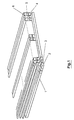
- Fig. 1 shows a perspective view of a stereoscopic display according to the invention with a flat panel display 1 which incorporates the pixel plane consisting of pixels 2 and 3 for the left and right image, which are arranged alternately in a row, so that a column consists of pixels for the left and right image, respectively, only. With this arrangement a so-called mixed stripe image is formed wherein the columns for left and right image alternate.
- a first lenticular lens sheet 4 is provided in front of the flat panel display 1 to generate the stereoscopic effect. This first lenticular lens sheet 4 is followed by a prism array sheet 5 consisting of prism arrays oriented along the pixel columns.
- prism arrays deflect the main lobe of the emanating light of the pixels to the viewing point for the right and left image, respectively.
- the angle of the prisms vary in respect to the relative position of the pixel arrays to the middle of the flat panel display. Therefore in the middle of the flat panel display 1 the prisms are degraded to a flat plate.
- second lenticular lens sheet 6 is provided wherein the angle of the lens stripe vary as a function of the relative position to the middle of the flat panel display 1.
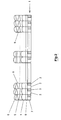
- Fig. 2 shows a cross section of the stereoscopic display according to Fig. 1.
- a flat panel display 1 consisting of the pixel plane 7 with alternating pixels 2 and 3 and a front glass 8 has on top first lenticular lens sheet 4 followed by a prism array sheet 5 and a second lenticular lens sheet 6.
- the angle of the individual prisms of the prism array sheet 5 and the individual lenses of the second lenticular lens sheet 6 vary as a function of the relative distance to the middle of the display 1.
- the individual lenses and prisms of the first and second lenticular lens sheet and the prism array sheet cover a row of two pixels each.
- the area between the sheets 4, 5, 6 can be filled by any material, may be for mechanical fixing or it may be even air. The optical characteristics of this material must be taken into account for the optical properties of the sheets 4, 5, 6.
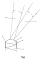
- Fig. 3 shows a cross section through the prism and area stripes in more detail.
- a flat panel display 1 consisting of a pixel plane 7 with pixels 2 and 3 for the left and right image, respectively, is followed by a front glass 8.
- the front glass 8 On top of the front glass 8 there is the first lenticular lens sheet 4 provided followed by a prism array sheet 5 and a second lenticular lens sheet 6.
- a barrier 9 is provided between the different sheets 4, 5 and 6 is so chosen that only the main lobe generated by the first lens can pass along the light absorbing barriers. Therefore, this arrangement with two lenses and the prism creates a ray for the right eye and a ray for the left eye, each focused to the respective viewing point for the right and left eye.
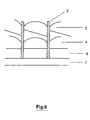
- Fig. 4 shows an enlarged view of Fig. 3, showing the prism of the prism array sheet 5 and the lens of the second lenticular lens sheet 6 together with barriers 9 on both sides in more detail.
- a ray 10 for the right eye and a ray 11 for the left eye are generated.
- Fig. 5 shows a detailed cross section through a second embodiment of the invention, wherein the lenses and prism arrays are applied to one pixel only, i.e. to one pixel row. Therefore the pixel rows are separated by barriers 9.
- the expanded angle of the projective rays is about the width of the human face at the viewing position. Therefore the display system is not a stereoscopic display, but a private display where the image can be viewed only in the viewing position.
- the angles of the prisms of the prism array sheet 5 and shapes of the lenticular lenses of the lenticular lens sheets 4 and 6 are different at each pixel position.
- Fig. 6 shows a cross section through a third embodiment of the invention, wherein the second lenticular lens sheet 6 and the prism array sheet 5 are combined so that the second lenticular lens sheet 6 has the lens and the prism effect of the first and second embodiments.
- the shapes of the lenticular lenses of the first lenticular lens sheet 4 and the second lenticular lens sheet 6 are different for each pixel position.
- the set of pixels are separated by barriers which rest on the flat panel display 1.
- Fig. 7 shows a cross section through a fourth embodiment of the invention, wherein the prism array sheet 5 is arranged in the space between the flat panel display 1 and the first lenticular lens sheet 4.
- the angles of the prisms and the lenses of the prism array sheet 5 and the lenticular lens sheet 4 vary depending the pixel position.
- Fig. 8 shows a cross section through a fifth embodiment of the invention, wherein the first lenticular lens sheet 4 is omitted and the prism array sheet 5 and the second lenticular lens sheet 6 are combined to form a lenticular lens sheet with the lens and prism effect of the foregoing examples.
- barriers 9 are resting on the flat panel display 1 and separate the prism/lens stripes of the combined second lenticular lens sheet.
- the shapes and angles of the lenticular lenses of the second lenticular lens sheet are different for each pixel position.
- Fig. 9 finally shows a cross section through a sixth embodiment of the invention comprising a flat panel display 1, a first lenticular lens sheet 4 on top of it, followed by a prism array sheet 5.
- the individual sections of the prism array sheet and the lenticular lens sheet 4 are separated by barriers 9 resting on the flat panel display.
- the angles of the prism and the shape of the lenticular lenses of the lenticular lens sheet 4 are different for each pixel position.
Landscapes
- Physics & Mathematics (AREA)
- General Physics & Mathematics (AREA)
- Optics & Photonics (AREA)
- Geometry (AREA)
- Stereoscopic And Panoramic Photography (AREA)
- Testing, Inspecting, Measuring Of Stereoscopic Televisions And Televisions (AREA)
Claims (14)
- Dispositif d'affichage stéréoscopique à lentille lenticulaire (4, 12) comprenant un écran (1) dans lequel des pixels (2, 3) pour les images de gauche et de droite alternent pour former une image à bandes mixtes, ainsi qu'une couche de lentilles lenticulaires (4, 12) devant l'écran, et possédant un dispositif de limitation des lobes (9) pour limiter l'effet des rayons émanant des différents ensembles de pixels (2, 3) sur le lobe principal, caractérisé en ce que
le dispositif d'affichage comprend en outre un dispositif de réfraction (5) permettant de diriger les lobes principaux de l'image de gauche vers l'un des points de visée de l'image de gauche et les lobes principaux de l'image de droite vers l'un des points de visée de l'image de droite. - Dispositif d'affichage stéréoscopique conformément à la revendication 1, où le dispositif de limitation des lobes (9) est constitué de barrières (9) placées entre les ensembles adjacents de pixels (2, 3).
- Dispositif d'affichage stéréoscopique conformément à la revendication 2, où l'ensemble de pixels (2, 3) comprend deux pixels voisins (2, 3) vus dans la direction de balayage.
- Dispositif d'affichage stéréoscopique conformément à la revendication 2, où l'ensemble de pixels (2, 3) comprend un pixel (2, 3).
- Dispositif d'affichage stéréoscopique conformément aux revendications 1 à 4, où le dispositif de réfraction (5) est formé par une couche de matrices de prismes (5).
- Dispositif d'affichage stéréoscopique conformément à la revendication 5, où chaque matrice de prismes (5) est placée à un angle approprié pour diriger le lobe principal correspondant vers le point de visée correspondant.
- Dispositif d'affichage stéréoscopique conformément à la revendication 6, où une seconde couche de lentilles lenticulaires (6) est placée devant la couche de matrices de prismes (5).
- Dispositif d'affichage stéréoscopique conformément à la revendication 7, où la forme des lentilles lenticulaires est différente à chaque position d'ensemble de pixels.
- Dispositif d'affichage stéréoscopique conformément à la revendication 1, où le dispositif de réfraction (5) est formé par une couche de lentilles lenticulaires combinée à des prismes.
- Dispositif d'affichage stéréoscopique conformément à la revendication 9, où la forme des lentilles lenticulaires des deux couches de lentilles lenticulaires (4, 6) est différente à chaque position d'ensemble de pixels.
- Dispositif d'affichage stéréoscopique conformément à la revendication 1, où le dispositif de réfraction (5) est placé entre l'écran (1) et la couche de lentilles lenticulaires (4).
- Dispositif d'affichage stéréoscopique conformément à la revendication 11, où le dispositif de réfraction (5) est formé par une couche de matrices de prismes.
- Dispositif d'affichage stéréoscopique conformément à la revendication 12, où chaque matrice de prismes (5) est placée à un angle de déviation approprié.
- Dispositif d'affichage stéréoscopique conformément à l'une des revendications précédentes, où la couche de lentilles lenticulaires (4) ou la couche de matrices de prismes (5) est placée directement sur l'écran plat (1).
Applications Claiming Priority (2)
| Application Number | Priority Date | Filing Date | Title |
|---|---|---|---|
| GB9523189 | 1995-11-13 | ||
| GB9523189A GB2307058A (en) | 1995-11-13 | 1995-11-13 | Stereoscopic display with lens,prism and barrier arrays |
Publications (3)
| Publication Number | Publication Date |
|---|---|
| EP0773462A2 EP0773462A2 (fr) | 1997-05-14 |
| EP0773462A3 EP0773462A3 (fr) | 1998-03-25 |
| EP0773462B1 true EP0773462B1 (fr) | 2002-04-17 |
Family
ID=10783804
Family Applications (1)
| Application Number | Title | Priority Date | Filing Date |
|---|---|---|---|
| EP96117593A Expired - Lifetime EP0773462B1 (fr) | 1995-11-13 | 1996-11-02 | Dispositif d'affichage privé, stéréoscopique à lentille lenticulaire |
Country Status (6)
| Country | Link |
|---|---|
| US (1) | US5852512A (fr) |
| EP (1) | EP0773462B1 (fr) |
| JP (1) | JP3980685B2 (fr) |
| CN (1) | CN1123791C (fr) |
| DE (1) | DE69620710T2 (fr) |
| GB (1) | GB2307058A (fr) |
Families Citing this family (43)
| Publication number | Priority date | Publication date | Assignee | Title |
|---|---|---|---|---|
| US6859240B1 (en) | 2000-01-27 | 2005-02-22 | Mems Optical Inc. | Autostereoscopic display |
| WO2001020386A2 (fr) * | 1999-09-17 | 2001-03-22 | Mems Optical, Inc. | Affichage autostereoscopique et procede d'affichage d'images multidimensionnelles, notamment d'images en couleurs |
| JP4049977B2 (ja) | 2000-09-01 | 2008-02-20 | パイオニア株式会社 | 通信端末装置、および通信端末装置に用いられるレンズアダプタ |
| US6867813B2 (en) * | 2001-04-27 | 2005-03-15 | Sony Corporation | Flat moldable HDTV display |
| AU2003293847A1 (en) * | 2002-12-13 | 2004-07-09 | Hentze Lissotschenko Patentverwaltungs Gmbh And Co. Kg | Device for recording and device for reproducing three-dimensional items of image information of an object |
| JP2004258163A (ja) * | 2003-02-25 | 2004-09-16 | Nec Corp | 立体画像表示装置及び立体画像表示方法 |
| CN1316287C (zh) * | 2003-07-07 | 2007-05-16 | 范文钦 | 立体显像装置 |
| US20050057491A1 (en) * | 2003-08-28 | 2005-03-17 | Eastman Kodak Company | Private display system |
| GB2406730A (en) | 2003-09-30 | 2005-04-06 | Ocuity Ltd | Directional display. |
| DE102005012348B3 (de) * | 2005-03-09 | 2006-07-27 | Seereal Technologies Gmbh | Sweet-Spot-Einheit für ein Multi-User-Display mit erweitertem Betrachterbereich |
| US20060283143A1 (en) * | 2005-06-15 | 2006-12-21 | York International Corporation | Frameless viewport |
| KR101170120B1 (ko) * | 2005-07-27 | 2012-07-31 | 삼성전자주식회사 | 비안경식 3차원 디스플레이 장치 |
| WO2007040471A1 (fr) * | 2005-09-16 | 2007-04-12 | Stereographics Corporation | Plaque de lentille autostereoscopique disposant de surfaces planes |
| US7697208B2 (en) * | 2005-10-04 | 2010-04-13 | Koninklijke Philips Electronics N.V. | 3D display with an improved pixel structure (pixelsplitting) |
| US20070091037A1 (en) * | 2005-10-21 | 2007-04-26 | Yee-Chun Lee | Energy Efficient Compact Display For Mobile Device |
| DE102006049438A1 (de) * | 2006-10-16 | 2008-04-17 | Forschungszentrum Jülich GmbH | Verfahren und Vorrichtung zur Rekonstruktion von dreidimensionalen Bildern |
| DE102007004508A1 (de) * | 2007-01-24 | 2008-07-31 | Seereal Technologies S.A. | Richtungsgesteuerte Beleuchtungseinheit mit Ablenkelement |
| WO2008142877A1 (fr) * | 2007-05-22 | 2008-11-27 | Sharp Kabushiki Kaisha | Elément optique, dispositif d'éclairage utilisant ce dernier, dispositif d'affichage et dispositif de réception de télévision |
| JP5021389B2 (ja) * | 2007-07-30 | 2012-09-05 | 独立行政法人情報通信研究機構 | 画像表示装置 |
| CN101383114B (zh) * | 2007-09-04 | 2012-12-26 | 富士迈半导体精密工业(上海)有限公司 | 广告牌 |
| CN101843105B (zh) * | 2007-11-02 | 2013-06-12 | 皇家飞利浦电子股份有限公司 | 自动立体显示设备 |
| KR101593515B1 (ko) | 2009-04-21 | 2016-02-29 | 삼성디스플레이 주식회사 | 입체영상 표시 장치 |
| US8363325B2 (en) * | 2010-09-14 | 2013-01-29 | Delphi Technologies, Inc. | Dual view display system |
| JP2011128636A (ja) * | 2011-01-20 | 2011-06-30 | Dainippon Printing Co Ltd | カラー立体表示装置 |
| EP2715433A1 (fr) * | 2011-05-30 | 2014-04-09 | Koninklijke Philips N.V. | Dispositif d'affichage autostéréoscopique |
| JP5943747B2 (ja) * | 2011-09-06 | 2016-07-05 | 三菱電機株式会社 | 立体映像表示装置 |
| GB2499634A (en) * | 2012-02-23 | 2013-08-28 | Virtual Typography Ltd | Multidirectional lenticular lens array |
| JP5365726B2 (ja) * | 2012-05-28 | 2013-12-11 | 大日本印刷株式会社 | カラー立体表示装置 |
| KR102191552B1 (ko) | 2012-06-01 | 2020-12-16 | 코닌클리케 필립스 엔.브이. | 무안경 입체 디스플레이 디바이스 및 구동 방법 |
| US9261641B2 (en) | 2013-03-25 | 2016-02-16 | 3M Innovative Properties Company | Dual-sided film with compound prisms |
| US9784902B2 (en) | 2013-03-25 | 2017-10-10 | 3M Innovative Properties Company | Dual-sided film with split light spreading structures |
| US9967546B2 (en) | 2013-10-29 | 2018-05-08 | Vefxi Corporation | Method and apparatus for converting 2D-images and videos to 3D for consumer, commercial and professional applications |
| US20150116458A1 (en) | 2013-10-30 | 2015-04-30 | Barkatech Consulting, LLC | Method and apparatus for generating enhanced 3d-effects for real-time and offline appplications |
| CN105093541A (zh) * | 2014-05-22 | 2015-11-25 | 华为技术有限公司 | 显示装置 |
| US10158847B2 (en) | 2014-06-19 | 2018-12-18 | Vefxi Corporation | Real—time stereo 3D and autostereoscopic 3D video and image editing |
| US9753362B2 (en) | 2015-04-06 | 2017-09-05 | Laurence Jay Shaw | Mounted lenticular grating with parallax ghosting mitigation for many-frame animation |
| RU2720660C2 (ru) * | 2015-11-10 | 2020-05-12 | Конинклейке Филипс Н.В. | Устройство отображения и способ управления устройством отображения |
| GB2569325B (en) | 2017-12-13 | 2020-05-06 | Imperial Innovations Ltd | Ear examination apparatus |
| US10298921B1 (en) | 2018-02-27 | 2019-05-21 | Looking Glass Factory, Inc. | Superstereoscopic display with enhanced off-angle separation |
| FR3107806B1 (fr) | 2020-03-03 | 2024-06-14 | C E P | Dispositif favorisant l’apport d’air et d’eau aux racines des végétaux en culture hors-sol |
| WO2021237065A1 (fr) | 2020-05-21 | 2021-11-25 | Looking Glass Factory, Inc. | Système et procédé associés à un afficheur d'image holographique |
| WO2021243037A1 (fr) * | 2020-05-27 | 2021-12-02 | Looking Glass Factory, Inc. | Système et procédé pour des dispositifs d'affichage holographique |
| US12587629B2 (en) | 2023-08-30 | 2026-03-24 | Looking Glass Factory, Inc. | Augmented superstereoscopic display |
Family Cites Families (13)
| Publication number | Priority date | Publication date | Assignee | Title |
|---|---|---|---|---|
| NL8202934A (nl) * | 1982-07-21 | 1984-02-16 | Philips Nv | Inrichting voor het weergeven van drie-dimensionale beelden. |
| US5036385A (en) * | 1986-03-07 | 1991-07-30 | Dimension Technologies, Inc. | Autostereoscopic display with multiple sets of blinking illuminating lines and light valve |
| EP0285796B1 (fr) * | 1987-03-02 | 1993-06-16 | Honeywell Inc. | Système optique de télémétrie |
| US4807965A (en) * | 1987-05-26 | 1989-02-28 | Garakani Reza G | Apparatus for three-dimensional viewing |
| US4987487A (en) * | 1988-08-12 | 1991-01-22 | Nippon Telegraph And Telephone Corporation | Method of stereoscopic images display which compensates electronically for viewer head movement |
| JPH0819461B2 (ja) * | 1988-12-09 | 1996-02-28 | 新日本製鐵株式会社 | 高張力鋼板の製造法 |
| DE3921061A1 (de) * | 1989-06-23 | 1991-01-03 | Hertz Inst Heinrich | Wiedergabeeinrichtung fuer dreidimensionale wahrnehmung von bildern |
| JP2911627B2 (ja) * | 1991-03-27 | 1999-06-23 | 株式会社日立製作所 | 大画面投写形ディスプレイ |
| GB2272555A (en) * | 1992-11-11 | 1994-05-18 | Sharp Kk | Stereoscopic display using a light modulator |
| GB2272597A (en) * | 1992-11-11 | 1994-05-18 | Sharp Kk | 3-D Display apparatus. |
| DE4312918A1 (de) * | 1993-04-14 | 1994-10-20 | Hertz Inst Heinrich | Wiedergabeeinrichtung |
| US5500765A (en) * | 1994-05-11 | 1996-03-19 | Dimension Technologies Inc. | Convertible 2D/3D autostereoscopic display |
| US5475419A (en) * | 1994-06-29 | 1995-12-12 | Carbery Dimensions, Ltd. | Apparatus and method for three-dimensional video |
-
1995
- 1995-11-13 GB GB9523189A patent/GB2307058A/en not_active Withdrawn
-
1996
- 1996-10-18 US US08/733,422 patent/US5852512A/en not_active Expired - Lifetime
- 1996-11-02 EP EP96117593A patent/EP0773462B1/fr not_active Expired - Lifetime
- 1996-11-02 DE DE69620710T patent/DE69620710T2/de not_active Expired - Lifetime
- 1996-11-04 CN CN96114508A patent/CN1123791C/zh not_active Expired - Lifetime
- 1996-11-11 JP JP29839596A patent/JP3980685B2/ja not_active Expired - Lifetime
Also Published As
| Publication number | Publication date |
|---|---|
| JP3980685B2 (ja) | 2007-09-26 |
| DE69620710T2 (de) | 2002-09-12 |
| CN1123791C (zh) | 2003-10-08 |
| GB2307058A (en) | 1997-05-14 |
| CN1160259A (zh) | 1997-09-24 |
| EP0773462A3 (fr) | 1998-03-25 |
| US5852512A (en) | 1998-12-22 |
| GB9523189D0 (en) | 1996-01-17 |
| EP0773462A2 (fr) | 1997-05-14 |
| JPH09179067A (ja) | 1997-07-11 |
| DE69620710D1 (de) | 2002-05-23 |
Similar Documents
| Publication | Publication Date | Title |
|---|---|---|
| US5852512A (en) | Private stereoscopic display using lenticular lens sheet | |
| KR100600459B1 (ko) | 입체 표시 방법 및 장치 | |
| JP5122061B2 (ja) | 自動立体ディスプレイ | |
| JP4367775B2 (ja) | デュアルビューディスプレイ | |
| US5991074A (en) | Stereoscopic image display apparatus | |
| JP4404311B2 (ja) | マルチビュー指向性ディスプレイ | |
| JP4470355B2 (ja) | メガネなし表示システム | |
| US8125513B2 (en) | Stereoscopic display device and display method | |
| US7064895B2 (en) | Stereoscopic image display method and stereoscopic image display apparatus using it | |
| KR100658545B1 (ko) | 입체 화상 재생 장치 | |
| EP0779531B1 (fr) | Dispositif d'affichage stéréoscopique | |
| EP1708010A1 (fr) | Appareil d'affichage d'image | |
| JPH08331605A (ja) | 立体表示装置 | |
| US20070268590A1 (en) | Lenticule and Prism Unit | |
| US20070183033A1 (en) | Multi-lens lenticular system and lighting device for an autostereoscopic display | |
| JPH10232369A (ja) | 立体画像表示装置 | |
| US20080259157A1 (en) | Lenticular Design By Applying Light Blocking Feature | |
| JP3790072B2 (ja) | 画像表示装置 | |
| JP2006309178A (ja) | 画像表示装置 | |
| KR101324060B1 (ko) | 무안경 입체 영상 디스플레이 장치 | |
| JPH0682934A (ja) | 立体視用レンチキュラスクリーン | |
| JPH08331604A (ja) | 立体表示装置 | |
| JP3661494B2 (ja) | 指向性反射スクリーンおよび画像表示装置 | |
| JP7841743B2 (ja) | 裸眼立体映像表示装置 | |
| JPS5933449A (ja) | 立体視用透視板 |
Legal Events
| Date | Code | Title | Description |
|---|---|---|---|
| PUAI | Public reference made under article 153(3) epc to a published international application that has entered the european phase |
Free format text: ORIGINAL CODE: 0009012 |
|
| AK | Designated contracting states |
Kind code of ref document: A2 Designated state(s): DE FR GB IT |
|
| PUAL | Search report despatched |
Free format text: ORIGINAL CODE: 0009013 |
|
| AK | Designated contracting states |
Kind code of ref document: A3 Designated state(s): DE FR GB IT |
|
| RAP1 | Party data changed (applicant data changed or rights of an application transferred) |
Owner name: THOMSON MULTIMEDIA |
|
| 17P | Request for examination filed |
Effective date: 19980912 |
|
| 17Q | First examination report despatched |
Effective date: 19990831 |
|
| GRAG | Despatch of communication of intention to grant |
Free format text: ORIGINAL CODE: EPIDOS AGRA |
|
| GRAG | Despatch of communication of intention to grant |
Free format text: ORIGINAL CODE: EPIDOS AGRA |
|
| GRAH | Despatch of communication of intention to grant a patent |
Free format text: ORIGINAL CODE: EPIDOS IGRA |
|
| GRAH | Despatch of communication of intention to grant a patent |
Free format text: ORIGINAL CODE: EPIDOS IGRA |
|
| REG | Reference to a national code |
Ref country code: GB Ref legal event code: IF02 |
|
| GRAA | (expected) grant |
Free format text: ORIGINAL CODE: 0009210 |
|
| AK | Designated contracting states |
Kind code of ref document: B1 Designated state(s): DE FR GB IT |
|
| REF | Corresponds to: |
Ref document number: 69620710 Country of ref document: DE Date of ref document: 20020523 |
|
| REG | Reference to a national code |
Ref country code: GB Ref legal event code: 746 Effective date: 20020507 |
|
| ET | Fr: translation filed | ||
| REG | Reference to a national code |
Ref country code: FR Ref legal event code: D6 |
|
| PLBE | No opposition filed within time limit |
Free format text: ORIGINAL CODE: 0009261 |
|
| STAA | Information on the status of an ep patent application or granted ep patent |
Free format text: STATUS: NO OPPOSITION FILED WITHIN TIME LIMIT |
|
| 26N | No opposition filed |
Effective date: 20030120 |
|
| PG25 | Lapsed in a contracting state [announced via postgrant information from national office to epo] |
Ref country code: IT Free format text: LAPSE BECAUSE OF NON-PAYMENT OF DUE FEES;WARNING: LAPSES OF ITALIAN PATENTS WITH EFFECTIVE DATE BEFORE 2007 MAY HAVE OCCURRED AT ANY TIME BEFORE 2007. THE CORRECT EFFECTIVE DATE MAY BE DIFFERENT FROM THE ONE RECORDED. Effective date: 20051102 |
|
| REG | Reference to a national code |
Ref country code: FR Ref legal event code: PLFP Year of fee payment: 20 |
|
| PGFP | Annual fee paid to national office [announced via postgrant information from national office to epo] |
Ref country code: DE Payment date: 20151126 Year of fee payment: 20 Ref country code: GB Payment date: 20151130 Year of fee payment: 20 |
|
| PGFP | Annual fee paid to national office [announced via postgrant information from national office to epo] |
Ref country code: FR Payment date: 20151120 Year of fee payment: 20 |
|
| REG | Reference to a national code |
Ref country code: DE Ref legal event code: R071 Ref document number: 69620710 Country of ref document: DE |
|
| REG | Reference to a national code |
Ref country code: GB Ref legal event code: PE20 Expiry date: 20161101 |
|
| PG25 | Lapsed in a contracting state [announced via postgrant information from national office to epo] |
Ref country code: GB Free format text: LAPSE BECAUSE OF EXPIRATION OF PROTECTION Effective date: 20161101 |