EP0773483A2 - Entwicklungsvorrichtung mit Tonerkartusche - Google Patents
Entwicklungsvorrichtung mit Tonerkartusche Download PDFInfo
- Publication number
- EP0773483A2 EP0773483A2 EP96117934A EP96117934A EP0773483A2 EP 0773483 A2 EP0773483 A2 EP 0773483A2 EP 96117934 A EP96117934 A EP 96117934A EP 96117934 A EP96117934 A EP 96117934A EP 0773483 A2 EP0773483 A2 EP 0773483A2
- Authority
- EP
- European Patent Office
- Prior art keywords
- toner
- toner cartridge
- container
- mounting portion
- side walls
- Prior art date
- Legal status (The legal status is an assumption and is not a legal conclusion. Google has not performed a legal analysis and makes no representation as to the accuracy of the status listed.)
- Granted
Links
Images


Classifications
-
- G—PHYSICS
- G03—PHOTOGRAPHY; CINEMATOGRAPHY; ANALOGOUS TECHNIQUES USING WAVES OTHER THAN OPTICAL WAVES; ELECTROGRAPHY; HOLOGRAPHY
- G03G—ELECTROGRAPHY; ELECTROPHOTOGRAPHY; MAGNETOGRAPHY
- G03G15/00—Apparatus for electrographic processes using a charge pattern
- G03G15/06—Apparatus for electrographic processes using a charge pattern for developing
- G03G15/08—Apparatus for electrographic processes using a charge pattern for developing using a solid developer, e.g. powder developer
- G03G15/0822—Arrangements for preparing, mixing, supplying or dispensing developer
- G03G15/0865—Arrangements for supplying new developer
- G03G15/0867—Arrangements for supplying new developer cylindrical developer cartridges, e.g. toner bottles for the developer replenishing opening
-
- G—PHYSICS
- G03—PHOTOGRAPHY; CINEMATOGRAPHY; ANALOGOUS TECHNIQUES USING WAVES OTHER THAN OPTICAL WAVES; ELECTROGRAPHY; HOLOGRAPHY
- G03G—ELECTROGRAPHY; ELECTROPHOTOGRAPHY; MAGNETOGRAPHY
- G03G15/00—Apparatus for electrographic processes using a charge pattern
- G03G15/06—Apparatus for electrographic processes using a charge pattern for developing
- G03G15/08—Apparatus for electrographic processes using a charge pattern for developing using a solid developer, e.g. powder developer
- G03G15/0822—Arrangements for preparing, mixing, supplying or dispensing developer
- G03G15/0877—Arrangements for metering and dispensing developer from a developer cartridge into the development unit
- G03G15/0881—Sealing of developer cartridges
- G03G15/0882—Sealing of developer cartridges by a peelable sealing film
-
- G—PHYSICS
- G03—PHOTOGRAPHY; CINEMATOGRAPHY; ANALOGOUS TECHNIQUES USING WAVES OTHER THAN OPTICAL WAVES; ELECTROGRAPHY; HOLOGRAPHY
- G03G—ELECTROGRAPHY; ELECTROPHOTOGRAPHY; MAGNETOGRAPHY
- G03G15/00—Apparatus for electrographic processes using a charge pattern
- G03G15/06—Apparatus for electrographic processes using a charge pattern for developing
- G03G15/08—Apparatus for electrographic processes using a charge pattern for developing using a solid developer, e.g. powder developer
- G03G15/0822—Arrangements for preparing, mixing, supplying or dispensing developer
- G03G15/0865—Arrangements for supplying new developer
- G03G15/0867—Arrangements for supplying new developer cylindrical developer cartridges, e.g. toner bottles for the developer replenishing opening
- G03G15/087—Developer cartridges having a longitudinal rotational axis, around which at least one part is rotated when mounting or using the cartridge
- G03G15/0872—Developer cartridges having a longitudinal rotational axis, around which at least one part is rotated when mounting or using the cartridge the developer cartridges being generally horizontally mounted parallel to its longitudinal rotational axis
-
- G—PHYSICS
- G03—PHOTOGRAPHY; CINEMATOGRAPHY; ANALOGOUS TECHNIQUES USING WAVES OTHER THAN OPTICAL WAVES; ELECTROGRAPHY; HOLOGRAPHY
- G03G—ELECTROGRAPHY; ELECTROPHOTOGRAPHY; MAGNETOGRAPHY
- G03G15/00—Apparatus for electrographic processes using a charge pattern
- G03G15/14—Apparatus for electrographic processes using a charge pattern for transferring a pattern to a second base
- G03G15/18—Apparatus for electrographic processes using a charge pattern for transferring a pattern to a second base of a charge pattern
-
- G—PHYSICS
- G03—PHOTOGRAPHY; CINEMATOGRAPHY; ANALOGOUS TECHNIQUES USING WAVES OTHER THAN OPTICAL WAVES; ELECTROGRAPHY; HOLOGRAPHY
- G03G—ELECTROGRAPHY; ELECTROPHOTOGRAPHY; MAGNETOGRAPHY
- G03G21/00—Arrangements not provided for by groups G03G13/00 - G03G19/00, e.g. cleaning, elimination of residual charge
- G03G21/16—Mechanical means for facilitating the maintenance of the apparatus, e.g. modular arrangements
- G03G21/1642—Mechanical means for facilitating the maintenance of the apparatus, e.g. modular arrangements for connecting the different parts of the apparatus
-
- Y—GENERAL TAGGING OF NEW TECHNOLOGICAL DEVELOPMENTS; GENERAL TAGGING OF CROSS-SECTIONAL TECHNOLOGIES SPANNING OVER SEVERAL SECTIONS OF THE IPC; TECHNICAL SUBJECTS COVERED BY FORMER USPC CROSS-REFERENCE ART COLLECTIONS [XRACs] AND DIGESTS
- Y10—TECHNICAL SUBJECTS COVERED BY FORMER USPC
- Y10S—TECHNICAL SUBJECTS COVERED BY FORMER USPC CROSS-REFERENCE ART COLLECTIONS [XRACs] AND DIGESTS
- Y10S222/00—Dispensing
- Y10S222/01—Xerography
Definitions
- This invention relates to a developing device which is mounted on an image forming machine, such as an electrostatic copying apparatus, a printer, or a facsimile, to develop a latent electrostatic image to a toner image, and a toner cartridge applied to such a developing device.
- an image forming machine such as an electrostatic copying apparatus, a printer, or a facsimile
- an image forming machine forms a latent electrostatic image on an electrostatic photoconductor, develops this image to a toner image, and transfers the toner image on the photoconductor onto a sheet member, optionally a plain paper.
- a developing device for developing a latent electrostatic image to a toner image applies a so-called one component developer comprising only a toner, or a so-called two component developer comprising a toner and carrier particles onto the electrostatic photoconductor to develop a latent electrostatic image to a toner image. With such a developing device, the toner is consumed as development takes place, and a fresh toner needs to be fed where necessary.
- a toner cartridge mounting portion is disposed in the developing device, and a toner cartridge is detachably mounted on the toner cartridge mounting portion.
- the toner cartridge includes a container, and a toner accommodated in this container.
- a toner cartridge of the type including a generally cylindrical container is in wide use.
- a typical example of such a toner cartridge includes, in addition to the generally cylindrical container, a cover member which similarly has a generally cylindrical shape.
- the container is concentrically and rotatably integrated into the cover member.
- a toner discharge opening is formed in the peripheral wall of the container, and a toner passage opening is formed in the cover member.
- a typical example of the toner cartridge mounting portion in the developing device, to which the above-described toner cartridge is applied, has a pair of upright walls disposed with a predetermined spacing, and an insertion opening is formed in one of the pair of upright walls.
- the toner cartridge is longitudinally moved through the insertion opening, whereby the toner cartridge is inserted between the pair of upright walls.
- the container of the toner cartridge is rotated to bring the toner discharge opening formed in the peripheral wall of the container into alignment with the toner passage opening formed in the cover member.
- the toner discharge opening is unsealed, the toner accommodated in the container is flowed from inside the container through the toner discharge opening and the toner passage opening.
- the first step is to rotate the container, thereby displacing the toner discharge opening peripherally relative to the toner passage opening of the cover member to reseal the toner discharge opening. Then, the toner cartridge is withdrawn through the insertion opening.
- the toner cartridge mounting portion needs to be provided with guide means for appropriately guiding the toner cartridge longitudinally moved through the insertion opening.
- Such guide means needs to extend over nearly the entire length of the slender toner cartridge.
- the toner cartridge mounting portion becomes relatively complicated in structure and expensive in cost.
- mounting and releasing operations for moving the toner cartridge in its longitudinal direction through the insertion opening are relatively tiresome.
- An object of the present invention is to provide a novel and improved developing device capable of mounting the toner cartridge on the toner cartridge mounting portion as required, by moving the toner cartridge nearly in its diametrical direction, without moving the toner cartridge in its longitudinal direction.
- Another object of the invention is to provide a novel and improved developing device in which the structure of the toner cartridge mounting portion is relatively simple and inexpensive.
- Still another object of the invention is to provide a novel and improved developing device in which operations for mounting and releasing the toner cartridge on and from the toner cartridge mounting portion are fully easy.
- a further object of the invention is to provide a novel and improved developing device in which a toner recovery container for recovering a toner removed from an electrostatic photoconductor after transfer of a toner image from the electrostatic photoconductor onto a sheet member is mounted on the toner cartridge so that the toner recovery container may be mounted and released in accordance with the mounting and release of the toner cartridge, thus making it possible to simultaneously perform the replacement of the toner cartridge and the replacement of the toner recovery container.
- a developing device including a toner cartridge mounting portion and a toner cartridge to be detachably mounted on the toner cartridge mounting portion;
- a toner cartridge for use in a developing device including a toner cartridge mounting portion which has a bottom wall having a toner acceptance opening formed therein, and a pair of supporting side walls disposed on the opposite side edges of the bottom wall, the inner surface of one of the supporting side walls having an engaging means disposed thereon;
- the toner cartridge includes a cover member which is generally cylindrical in shape and which has a toner passage opening formed in its peripheral wall.
- the container is concentrically and rotatably integrated into the cover member.
- the toner discharge opening of the container and the toner passage opening of the cover member are positioned so as to be peripherally displaced relative to each other, thereby sealing the toner discharge opening.
- the toner cartridge With the toner passage opening of the cover member being substantially aligned with the toner acceptance opening of the toner cartridge mounting portion, the toner cartridge is mounted on the toner cartridge mounting portion.
- the container is rotated to bring the toner discharge opening of the container into substantial alignment with the toner passage opening of the cover member to unseal the toner discharge opening.
- the toner is flowed through the toner discharge opening, the toner passage opening, and the toner acceptance opening.
- a rotary member so as to be rotatable between a first angular position and a second angular position about a central axis of rotation extending in the longitudinal direction of the toner cartridge mounting portion.
- the engaging means is formed on the inner surface of the rotary member.
- the container When the rotary member is rotated from the first angular position to the second angular position, the container is rotated accordingly to substantially align the toner discharge opening with the toner passage opening.
- the toner discharge opening When the rotary member is returned from the second angular position to the first angular position, the toner discharge opening is position so as to be peripherally displaced relative to the toner passage opening.
- a grip arm is formed on the rotary member.
- a visible mark is made on the peripheral surface of the rotary member, and a visible mark is made also on the engaged means of the container.
- journaled portion On the other of the supporting side walls of the toner cartridge mounting portion, there are formed a journal hole and a guide groove extending from the journal hole to the outer edge. On the outer surface of the other side wall of the container of the toner cartridge, there is formed a journaled portion protruding longitudinally outwardly. In opposing the other side wall of the container of the toner cartridge to the inner surface of the other of the supporting side walls of the toner cartridge mounting portion, it is preferred that the journaled portion be introduced into the journal hole through the guide groove.
- the journaled portion is confined in the journal hole, and kept from moving from the journal hole to the guide groove.
- the guide groove has a width smaller than the diameter of the journal hole
- the journaled portion has a thickness substantially equal to or smaller than the width of the guide groove and has a width larger than the width of the guide groove and substantially equal to or smaller than the diameter of the journal hole.
- the cover member of the toner cartridge has a side wall positioned between the other side wall of the container and the other of the supporting side walls of the toner cartridge mounting portion. On this side wall, a toner recovery container mounting portion is disposed.
- the toner cartridge includes a toner recovery container to be detachably mounted on the toner recovery container mounting portion. A main portion of the toner recovery container mounted on the toner recovery container mounting portion is positioned adjacent the outer surface of the other of the supporting side walls of the toner cartridge mounting portion when the toner cartridge is mounted on the toner cartridge mounting portion.
- FIG. 1 shows an imaging unit equipped with a developing device constructed in accordance with the present invention.
- Such an imaging unit has a frame means generally designated by the numeral 2.
- the frame means 2 may be formed of a suitable plastic material.
- a developing device 10 constructed in accordance with the invention is mounted along with an image bearing means 4, a charging means 6 and a cleaning means 8.
- the image bearing means 4 is constructed of a rotating drum 12 having an electrostatic photoconductor disposed on the peripheral surface thereof.
- the rotating drum 12 is rotationally driven in the direction of an arrow 14.
- the charging means 6 is composed of a corona discharger for charging the peripheral surface of the rotating drum 12 to a specific polarity.
- the cleaning means 8 has a cleaning housing 16, in which a cleaning blade 18 is disposed.
- the cleaning blade 18 is formed of a flexible material such as synthetic rubber, and has its forward end portion pressed against the peripheral surface of the rotating drum 12.
- the developing device 10 has a development housing 20, in which a developing roller 22, a developer regulating member 24, a developer replenishing roller 26 and a developer conveying member 28 are mounted. Furthermore, a toner cartridge mounting portion 30 is disposed at an upper end portion of the development housing 20. A toner cartridge 32 is detachably mounted on the toner cartridge mounting portion 30 (the toner cartridge mounting portion 30 and the toner cartridge 32 will be described in more detail later).
- a developer to be used in the developing device 10 may be a so-called one component developer consisting merely of a toner sent out of the toner cartridge 32. Such a developer is conveyed to the developer replenishing roller 26 by the action of the developer conveying member 28 rotationally driven in the direction of an arrow 34.
- the developer replenishing roller 26 rotationally driven in the direction of an arrow 36 feeds the developer onto the developing roller 22.
- the developer held on the developing roller 22 rotationally driven in the direction of an arrow 38 has its layer thickness regulated by the developer regulating member 24 to have a required value.
- the developing roller 22 is composed of a metallic shaft member 40, and a synthetic rubber roller member 42 disposed on the peripheral surface of the shaft member 40. The developing roller 22 is elastically pressed against the rotating drum 12.
- the above-described imaging unit is detachably mounted at a required position of a machine body housing (not shown) of an image forming machine such as an electrostatic copying apparatus.
- the rotating drum 12 is rotationally driven in the direction of arrow 14.
- a charging zone 44 the peripheral surface of the rotating drum 12 is uniformly charged to a specific polarity by the charging means 6.
- an exposure zone 46 the peripheral surface of the rotating drum 12 is irradiated with light, which corresponds to an image to be produced, by a suitable optical system (not shown).
- a latent electrostatic image is formed on the peripheral surface of the rotating drum 12.
- a transfer member (not shown), optionally a plain paper, is intimately contacted with the peripheral surface of the rotating drum 12, and the toner image formed on the peripheral surface of the rotating drum 12 is transferred onto the transfer member.
- the transfer member having the transferred toner image is peeled from the peripheral surface of the rotating drum 12, and conveyed to a fixing means (not shown). After the toner image is fixed by the action of the fixing means, the transfer member is expelled to the outside of the machine body housing.
- a cleaning zone 52 residual toner remaining on the peripheral surface of the rotating drum 12 after transfer is removed from the peripheral surface of the rotating drum 12 by the action of the cleaning blade 18.
- the toner cartridge mounting portion 30 of the developing device 10 in the imaging unit includes a bottom wall 54 extending slenderly and substantially horizontally in the direction of the central axis of the rotating drum 12 (the direction perpendicular to the sheet face in Fig. 1), and a pair of supporting side walls 56 and 58 disposed at the opposite side edges of the bottom wall 54.
- the cross section of the bottom wall 54 is nearly semicircular.
- a sealing member 62 extending around the toner acceptance opening 60 is bonded onto the bottom wall 54.
- the sealing member 62 may be made of a foamed plastic material.
- bottom wall 54 On the bottom wall 54, there are further formed a pair of shoulder surfaces 53 and 55 extending substantially horizontally in the longitudinal direction on the outside of the sealing member 62.
- the pair of supporting side walls 56 and 58 extend substantially vertically upwardly from the opposite side edges of the bottom wall 54.
- a rotary member 64 is mounted on the inner surface of the supporting side wall 56 of the toner cartridge mounting portion 30.
- the rotary member 64 has a disc-shaped main portion 66, and a grip arm 68 of a nearly triangular shape protruding from the main portion 66.
- a circular hole is formed in the center of the main portion 66, and a forward end portion of a mounting member 70 extending through this circular hole is screwed to the supporting side wall 56.
- the rotary member 64 is mounted so as to be rotatable between a first angular position shown by a solid line and a second angular position shown by a two-dot chain line.
- the mounting member 70 extends substantially horizontally in the longitudinal direction of the toner cartridge mounting portion 30 (the direction perpendicular to the sheet face in Fig. 1).
- the rotary member 64 is mounted so as to be rotatable about a central axis of rotation (the central axis of the mounting member 70) extending substantially horizontally in the longitudinal direction of the toner cartridge mounting portion 30.
- a protrusion constituting an engaging means 78 is formed at the center of the inner surface of the main portion 66 of the rotary member 64. This protrusion may be in the shape of a partly cut off circle.
- a visible mark 80 composed of a triangular projection.
- a journal hole 82 and a guide groove 84 extending from the journal hole 82 to the outer edge are formed in the other supporting side wall 58.
- the journal hole 82 is nearly circular, and the guide groove 84 extends straightly at an angle of inclination, ⁇ , advantageously of from about 20 to 60 degrees to the horizontal.
- the width w1 of the guide groove 84 is advantageously smaller than the diameter d of the journal hole 82, say, about a third of the diameter d of the journal hole 82.
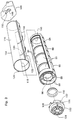
- the toner cartridge 32 in the illustrated embodiment includes a generally cylindrical container 86.
- the container 86 which may be molded from a suitable plastic material has a peripheral wall 88, and a toner discharge opening 90 is formed in a specific angular region of the peripheral wall 88.
- the toner discharge opening 90 may be in a longitudinally extending nearly rectangular shape.
- a plurality of ribs 92 extending across the toner discharge opening 90 are formed to reinforce the container 86.
- To the outer surface of the peripheral wall 88, a sealing member 94 extending around the toner discharge opening 90 is bonded.
- An end wall 96 is formed at one end portion of the container 86.
- a circular opening 98 is formed in this end wall 96.
- a closure member 100 is secured to the opening 98 by a suitable method, such as bonding or fusion bonding, after a toner is filled into the container 86 through the opening 98 as will be further described later, whereby the opening 98 is closed.
- the peripheral wall 88 extends longitudinally outwardly beyond the end wall 96.
- a nearly disc-shaped additional member 102 is mounted further. With reference to Fig. 6 along with Fig. 3, a through-hole constituting an engaged means 104 is formed at the center of the additional member 102 which may be molded from a suitable plastic material.
- the cross sectional shape of the through-hole corresponds to the cross sectional shape of the protrusion constituting the aforementioned engaging means 78.
- the engaging means 78 is received into the engaged means 104, whereby they are engaged.
- a visible mark 106 is formed which may be a slender triangular projection.
- the additional member 102 is further provided with a plurality of arcuate protruding pieces 107 and connecting nib pieces 108 which protrude inwardly from the peripheral edge of the additional member 102.
- This additional member 102 is connected to the other end surface of the peripheral wall 88 by securing the closure member 100 to the end wall 96 of the container 86, then positioning the arcuate protruding pieces 107 between the ribs 99 formed on the end wall 96 of the container 86, and simultaneously elastically engaging the connecting nib pieces 108 with the inner surface of an extending end portion of the peripheral wall 88. Since the arcuate protruding pieces 107 of the additional member 102 are positioned between the ribs 99, the relative rotation of the additional member 102 with respect to the container 86 is reliably inhibited.
- the other end of the container 86 is closed by an end wall 110 integrally formed with the peripheral wall 88.
- journaled portion 112 is integrally formed which protrudes longitudinally outwardly from the center of this outer surface.
- the cross sectional shape of a forward end portion of the journaled portion 112 is a shape corresponding to part of a circle, more specifically, a shape defined by the circumference of the circle, the diameter of the circle, and a chord extending parallel to this diameter.
- the width of the journaled portion 112 (the diameter of that circle), w2 is substantially equal to or slightly smaller than the diameter d of the journal hole 82, and larger than the width w1 of the guide groove 84.
- the thickness of the journaled portion 112, t is substantially equal to or slightly smaller than the width w1 of the guide groove 84.
- the toner cartridge 32 also includes a generally cylindrical cover member 114.
- the cover member 114 which may be molded from a suitable plastic material has a peripheral wall 116, and a toner passage opening 118 is formed in a specific angular region of the peripheral wall 116.
- the toner passage opening 118 may be in a longitudinally extending nearly rectangular shape.
- a plurality of ribs 120 extending across the toner passage opening 118 are formed to reinforce the cover member 114.
- On the outer surface of the peripheral wall 116 there are formed two contact pieces 122 and 124 with an angular spacing of nearly 180 degrees.
- Each of the contact pieces 122 and 124 protrudes substantially horizontally from the peripheral wall 116, and longitudinally extends over nearly the entire length of the peripheral wall 116.
- One end of the cover member 114 is wholly opened.
- an end wall 126 integrally molded with the peripheral wall 116 is disposed at the other end of the cover member 114.
- an opening 128, optionally circular, is formed.
- On the outer surface of the end wall 126 a toner recovery container mounting portion 130 is formed.
- the toner recovery container mounting portion 130 is composed of a lower regulating rail 132, and an upper regulating rail 134 disposed upwardly of the lower regulating rail 132 with a spacing.
- each of the guided pieces 140 has an inclined portion 142 extending longitudinally outwardly from the central portion toward the peripheral edge portion of the end surface 126, and a non-inclined portion 144 extending as a continuum from the inclined portion 142 and parallel to the end surface 126.
- a toner recovery container 146 is combined with the toner cartridge 32 to be mounted on the toner cartridge mounting portion 30.
- a connecting portion 148 is integrally formed at an upper end portion of one side surface of the toner recovery container 146, which may be molded from a suitable plastic material.
- This connecting portion 148 has a regulated rail 150.
- the shape of the regulated rail 150 corresponds to the shape of a space defined between the lower regulating rail 132 and the upper regulating rail 134 of the toner recovery container mounting portion 130 disposed on the cover member 114.
- the toner cartridge 32 is subjected to assembly in the following manner: First, the container 86 is inserted into the cover member 114 through the one opened end of the cover member 114. On this occasion, the container 86 is brought to an angular position where its toner discharge opening 90 becomes open upwardly. The cover member 114, on the other hand, is brought to an angular position where its toner passage opening 118 becomes open downwardly. Hence, the toner discharge opening 90 and the toner passage opening 118 are positioned so as to be peripherally displaced relative to each other, so that the toner discharge opening 118 of the container 86 is closed by the peripheral wall 116 of the cover member 114.
- the sealing member 94 bonded to the peripheral wall 88 of the container 86 is intimately contacted with the inner surface of the peripheral wall 116 of the cover member 114, thereby fully sealing the toner discharge opening 90.
- the journaled portion 112 formed on the end wall 110 of the container 86 protrudes through the opening 128 formed in the end wall 126 of the cover member 114.
- a required amount of toner is filled into the container 86 through the one opened end surface of the cover member 114 and the opening 98 formed in the end wall 96 of the container 86.
- the closure member 100 is secured to the end wall 96 of the container 86 to close the opening 98, whereby the toner is sealed up in the container 86.
- the additional member 102 is coupled to one end of the container 86.
- the toner recovery container 146 is detachably mounted on the toner recovery container mounting portion 130 formed on the end wall 126 of the cover member 114.
- the mounting of the toner recovery container 146 is performed by inserting the regulated rail 150 of the connecting portion 148 of the toner recovery container 146 into the space between the lower regulating rail 132 and the upper regulating rail 134 of the toner recovery container mounting portion 130 of the cover member 114, with at least one of the lower regulating rail 132, the upper regulating rail 134 and the regulated rail 150 being somewhat deformed elastically.
- the toner cartridge 32 In mounting the toner cartridge 32 on the toner cartridge mounting portion 30, the toner cartridge 32 is not moved longitudinally, but lowered in a direction normal to the longitudinal direction, and approached to the toner cartridge mounting portion 30. Then, the toner cartridge 32 is brought to a state in which it extends somewhat upwardly inclinedly from the one end, where the additional member 102 is disposed, toward the other end where the journaled portion 112 is disposed. In this state, the engaged means 104 (i.e. the through-hole) disposed in the additional member 102 is engaged with the engaging means 78 (i.e.
- the protrusion disposed on the rotary member 64 of the toner cartridge mounting portion 30.
- the visible mark 80 formed on the rotary member 64 and the visible mark 106 formed on the additional member 102 are aligned, the angular position of the toner cartridge 32 relative to the rotary member 64 is appropriately set, whereby the engaged means 104 is appropriately positioned relative to the engaging means 78.
- the other end of the toner cartridge 32 is moved to introduce the journaled portion 112 formed on the container 86 into the journal hole 82 through the guide groove 84.
- the journaled portion 112 has its width direction conformed to the extending direction of the guide groove 84.
- the forward edges of the guided pieces 140 formed on the end wall 126 of the cover member 114 are contacted with the inner surface of the supporting side wall 58.
- the toner cartridge 32 is guided toward the supporting side wall 56, whereby the longitudinal position of the toner cartridge 32 relative to the toner cartridge mounting portion 30 is regulated.
- the pair of contact pieces 122 and 124 formed on the cover member 114 of the toner cartridge 32 are abutted against the pair of shoulder surfaces 53 and 55 disposed in the toner cartridge mounting portion 30.
- the sealing member 62 disposed in the toner cartridge mounting portion 30 is intimately contacted with the outer surface of the peripheral wall 116 of the cover member 114 at the peripheral edge portion of the toner passage opening 118.
- the grip arm 68 is gripped with fingers to rotate the rotary member 64 from the first angular position shown by the solid line in Fig. 2 to the second, angular position shown by the two-dot chain line in Fig. 2. Since the engaging means 78 disposed on the rotary member 74 has engaged the engaged means 104 disposed in the additional member 102 coupled to the container 86, the container 86 is also rotated clockwise through a required angle in Fig. 1 in accordance with that rotation of the rotary member 64.
- the cover member 114 of the toner cartridge 32 Since the cover member 114 of the toner cartridge 32 has its pair of contact pieces 122 and 124 abutting against the pair of shoulder surfaces 53 and 55 of the toner cartridge mounting portion 30, the cover member 114 is prevented from rotating together with the container 86.
- the toner discharge opening 90 formed in the container 86 is aligned with the toner passage opening 118 of the cover member 114.
- the toner discharge opening 90 is unsealed, whereupon the toner inside the container 86 is flowed through the toner discharge opening 90, the toner passage opening 118 and the toner acceptance opening 60, and fed into the development housing 20.
- journaled portion 112 is rotated in the journal hole 82 through a required angle, so that the width direction of the journaled portion 112 becomes nearly normal to the guide groove 84. Hence, it becomes impossible to release the journaled portion 112 from the journal hole 82, with the result that the journaled portion 112 is confined in the journal hole 82.
- the end wall 126 of the cover member 114 is positioned inwardly of the supporting side wall 58 (more specifically, between the end wall 110 of the container 86 and the supporting side wall 58), while the toner recovery container 146 (shown by the two-dot chain line in Figs. 1 and 7) mounted on the toner recovery container mounting portion 130 disposed on the end wall 126 is positioned outwardly of the supporting side wall 58.
- a toner introduction opening (not shown) is formed in the toner recovery container 146, and the outlet opening of a toner carriage pipe (not shown) is made to communicate with this introduction opening.
- the toner removed from the peripheral surface of the rotating drum 12 by the action of the cleaning blade 18 of the cleaning means 8 is conveyed to the toner carriage pipe by a suitable conveying means, and introduced into the toner recovery container 146 through the toner carriage pipe.
- the relationship between the toner carriage pipe and the toner recovery container 146 is disclosed in U.S. Patent Application Serial No. 08/680,012 (European Patent Application No. 96 122 168.8) of S. Taniguchi et al. Disclosures made therein will be cited in the present specification, and an explanation for that relationship will be omitted herein.
- the first step is to grip the grip arm 68 with fingers, and rotate the rotary member 64 from the second angular position shown by the two-dot chain line in Fig. 2 to the first angular position shown by the solid line in Fig. 2.
- the container 86 is rotated counterclockwise through a required angle in Fig. 1 to be returned to its initial angular position (the angular position prior to the mounting of the toner cartridge 32 on the toner cartridge mounting portion 30).
- the toner discharge opening 90 of the container 86 is displaced in the peripheral direction from the toner passage opening 118 of the cover member 114 to reseal the toner discharge opening 90. Since the container 86 is rotated counterclockwise through a required angle in Fig. 1, the widthwise direction of the journaled portion 112 is brought into agreement with the extending direction of the guide groove 84. Thus, the journaled portion 112 becomes releasable from the journal hole 82 through the guide groove 84. Then, the journaled portion 112 is released from the journal hole 82, whereafter the engaged means 104 is released from the engaging means 78 to release the whole of the toner cartridge 32 from the toner cartridge mounting portion 30.
Landscapes
- Physics & Mathematics (AREA)
- General Physics & Mathematics (AREA)
- Dry Development In Electrophotography (AREA)
Applications Claiming Priority (3)
| Application Number | Priority Date | Filing Date | Title |
|---|---|---|---|
| JP292551/95 | 1995-11-10 | ||
| JP29255195 | 1995-11-10 | ||
| JP29255195 | 1995-11-10 |
Publications (3)
| Publication Number | Publication Date |
|---|---|
| EP0773483A2 true EP0773483A2 (de) | 1997-05-14 |
| EP0773483A3 EP0773483A3 (de) | 1999-08-18 |
| EP0773483B1 EP0773483B1 (de) | 2002-02-13 |
Family
ID=17783238
Family Applications (1)
| Application Number | Title | Priority Date | Filing Date |
|---|---|---|---|
| EP96117934A Expired - Lifetime EP0773483B1 (de) | 1995-11-10 | 1996-11-08 | Entwicklungsvorrichtung mit Tonerkartusche |
Country Status (9)
| Country | Link |
|---|---|
| US (1) | US5809384A (de) |
| EP (1) | EP0773483B1 (de) |
| KR (1) | KR970028902A (de) |
| CN (1) | CN1151538A (de) |
| AU (1) | AU7068696A (de) |
| CA (1) | CA2189482A1 (de) |
| DE (1) | DE69619199T2 (de) |
| SG (1) | SG75103A1 (de) |
| TW (1) | TW311186B (de) |
Cited By (2)
| Publication number | Priority date | Publication date | Assignee | Title |
|---|---|---|---|---|
| EP0744671A3 (de) * | 1995-05-23 | 1999-03-31 | Mita Industrial Co. Ltd. | Tonerbehälter für ein Bilderzeugungsgerät |
| US6134410A (en) * | 1996-01-29 | 2000-10-17 | Nakajima; Shigeki | Toner cartridge and drum cartridge for receiving the toner cartridge therein |
Families Citing this family (15)
| Publication number | Priority date | Publication date | Assignee | Title |
|---|---|---|---|---|
| JP3408166B2 (ja) * | 1997-09-30 | 2003-05-19 | キヤノン株式会社 | トナー供給容器及び電子写真画像形成装置 |
| JP2000250310A (ja) * | 1999-02-26 | 2000-09-14 | Brother Ind Ltd | 画像形成装置、感光体カートリッジ及び現像カートリッジ |
| JP3602008B2 (ja) * | 1999-07-30 | 2004-12-15 | 株式会社沖データ | トナーカートリッジおよびその製造方法 |
| US6289182B1 (en) * | 2000-02-18 | 2001-09-11 | Toshiba Tec Kabushiki Kaisha | Method and apparatus for discriminating toner bottle types, stirring toner, and detecting the amount of remaining toner |
| DE60312426T2 (de) * | 2002-04-24 | 2007-11-29 | Canon K.K. | Entwicklerzufuhrbehälter |
| AU2002347620A1 (en) * | 2002-09-30 | 2004-04-19 | System S.P.A. | A device for containing and supplying loose material |
| JP3824991B2 (ja) * | 2002-11-21 | 2006-09-20 | 株式会社沖データ | トナーカートリッジ装着構造及び画像形成装置 |
| JP4689422B2 (ja) * | 2005-09-27 | 2011-05-25 | 株式会社沖データ | 現像剤カートリッジ、画像形成ユニット及び画像形成装置 |
| US7647005B2 (en) * | 2006-03-27 | 2010-01-12 | Brother Kogyo Kabushiki Kaisha | Process unit, toner box and image forming apparatus |
| US7639968B2 (en) * | 2006-03-27 | 2009-12-29 | Brother Kogyo Kabushiki Kaisha | Process unit and image forming apparatus |
| JP4882759B2 (ja) * | 2006-03-27 | 2012-02-22 | ブラザー工業株式会社 | プロセスユニット、トナーボックスおよび画像形成装置 |
| US7587155B2 (en) * | 2006-03-27 | 2009-09-08 | Brother Kogyo Kabushiki Kaisha | Process cartridge and image forming apparatus |
| JP2007298543A (ja) * | 2006-04-27 | 2007-11-15 | Fuji Xerox Co Ltd | トナーカートリッジ |
| JP4411554B2 (ja) * | 2007-03-01 | 2010-02-10 | ブラザー工業株式会社 | トナーカートリッジ、現像装置および画像形成装置 |
| EP3700752B1 (de) | 2018-04-23 | 2025-09-03 | Hewlett-Packard Development Company, L.P. | Identifikatoren von verbrauchskomponenten |
Family Cites Families (9)
| Publication number | Priority date | Publication date | Assignee | Title |
|---|---|---|---|---|
| JP2578228B2 (ja) * | 1989-12-26 | 1997-02-05 | 沖電気工業株式会社 | トナー現像装置とそのトナーカートリッジ着脱方法 |
| JPH049980A (ja) * | 1990-04-27 | 1992-01-14 | Mita Ind Co Ltd | トカー補給装置 |
| US5294960A (en) * | 1990-11-06 | 1994-03-15 | Canon Kabushiki Kaisha | Detachable two-frame process cartridge for an image forming apparatus |
| US5541714A (en) * | 1992-05-18 | 1996-07-30 | Fujitsu Limited | Developer cartridge and image forming apparatus using the same |
| JP3060725B2 (ja) * | 1992-06-30 | 2000-07-10 | 富士通株式会社 | 現像剤カ−トリッジ及びこれを用いた画像形成装置 |
| US5331378A (en) * | 1993-07-29 | 1994-07-19 | Lexmark International, Inc. | Toner cartridge with independent driven systems |
| SG70990A1 (en) * | 1993-12-28 | 2000-03-21 | Canon Kk | Developer cartridge and remanufacturing method therefor |
| US5614996A (en) * | 1994-03-03 | 1997-03-25 | Kyocera Corporation | Toner storage unit, residual toner collect unit, toner container with these units and image forming apparatus with such toner container |
| JP3392256B2 (ja) * | 1994-04-22 | 2003-03-31 | 株式会社リコー | 画像形成装置 |
-
1996
- 1996-10-31 US US08/742,683 patent/US5809384A/en not_active Expired - Lifetime
- 1996-11-04 CA CA002189482A patent/CA2189482A1/en not_active Abandoned
- 1996-11-05 TW TW085113503A patent/TW311186B/zh active
- 1996-11-05 SG SG1996011034A patent/SG75103A1/en unknown
- 1996-11-08 EP EP96117934A patent/EP0773483B1/de not_active Expired - Lifetime
- 1996-11-08 KR KR1019960052837A patent/KR970028902A/ko not_active Withdrawn
- 1996-11-08 CN CN96120517A patent/CN1151538A/zh active Pending
- 1996-11-08 DE DE69619199T patent/DE69619199T2/de not_active Expired - Lifetime
- 1996-11-11 AU AU70686/96A patent/AU7068696A/en not_active Abandoned
Cited By (3)
| Publication number | Priority date | Publication date | Assignee | Title |
|---|---|---|---|---|
| EP0744671A3 (de) * | 1995-05-23 | 1999-03-31 | Mita Industrial Co. Ltd. | Tonerbehälter für ein Bilderzeugungsgerät |
| US6134410A (en) * | 1996-01-29 | 2000-10-17 | Nakajima; Shigeki | Toner cartridge and drum cartridge for receiving the toner cartridge therein |
| US6151472A (en) * | 1996-01-29 | 2000-11-21 | Oki Data Corporation | Toner cartridge and drum cartridge for receiving the toner cartridge therein |
Also Published As
| Publication number | Publication date |
|---|---|
| CN1151538A (zh) | 1997-06-11 |
| CA2189482A1 (en) | 1997-05-11 |
| SG75103A1 (en) | 2000-09-19 |
| EP0773483B1 (de) | 2002-02-13 |
| KR970028902A (ko) | 1997-06-24 |
| AU7068696A (en) | 1997-05-15 |
| EP0773483A3 (de) | 1999-08-18 |
| DE69619199D1 (de) | 2002-03-21 |
| US5809384A (en) | 1998-09-15 |
| DE69619199T2 (de) | 2002-10-17 |
| TW311186B (de) | 1997-07-21 |
Similar Documents
| Publication | Publication Date | Title |
|---|---|---|
| US5809384A (en) | Developing device and toner cartridge applied to same | |
| EP0871092B1 (de) | Tonerbehälter, Arbeitskartusche und Bilderzeugungsgerät | |
| EP1533664B1 (de) | Entwicklerzufuhrbehälter | |
| JP3120723B2 (ja) | トナー容器及びこれを用いた複写機 | |
| US6714749B2 (en) | Cartridge detachably mountable on image forming apparatus | |
| KR100434643B1 (ko) | 화상 형성 장치 및 화상 형성 장치 내에 제거 가능하게장착할 수 있는 현상제 공급 용기 | |
| US7983589B2 (en) | Developing apparatus, process cartridge, and image forming apparatus | |
| US20060245784A1 (en) | Process cartridge and image forming apparatus | |
| KR100523775B1 (ko) | 현상제 공급 장치용 재생 방법 | |
| JP3572500B2 (ja) | 現像剤補給装置及び現像剤カートリッジ | |
| EP1584991B1 (de) | Entwicklerentladungseinheit, Entwicklernachfüllkassette, Entwicklertransportsystem und Bilderzeugungsgerät | |
| JP4368331B2 (ja) | トナーボトル及び画像形成装置 | |
| JP2004126018A (ja) | カートリッジ及び画像形成装置 | |
| JPS645707B2 (de) | ||
| JPH09197818A (ja) | トナーカートリッジ | |
| JP3571873B2 (ja) | トナー搬送翼及びトナー供給容器 | |
| US6181898B1 (en) | Developing apparatus | |
| EP2026141A2 (de) | Entwicklerkartusche, Entwicklervorrichtung und Bilderzeugungsvorrichtung | |
| JPS5953868A (ja) | 現像剤貯蔵容器 | |
| JP2002341648A (ja) | トナー補給装置、および画像形成装置 | |
| JP2000098724A (ja) | 粉体容器とこれを用いた現像装置 | |
| CA2174872C (en) | Toner supply insert | |
| JP3239260B2 (ja) | 現像装置及びこれに適用されるトナーカートリッジ | |
| JP3530586B2 (ja) | トナーカートリッジ | |
| JP3225483B2 (ja) | トナー搬送器 |
Legal Events
| Date | Code | Title | Description |
|---|---|---|---|
| PUAI | Public reference made under article 153(3) epc to a published international application that has entered the european phase |
Free format text: ORIGINAL CODE: 0009012 |
|
| AK | Designated contracting states |
Kind code of ref document: A2 Designated state(s): CH DE ES FR GB IT LI |
|
| PUAL | Search report despatched |
Free format text: ORIGINAL CODE: 0009013 |
|
| AK | Designated contracting states |
Kind code of ref document: A3 Designated state(s): CH DE ES FR GB IT LI |
|
| 17P | Request for examination filed |
Effective date: 19991125 |
|
| RAP1 | Party data changed (applicant data changed or rights of an application transferred) |
Owner name: KYOCERA MITA CORPORATION |
|
| 17Q | First examination report despatched |
Effective date: 20000921 |
|
| GRAG | Despatch of communication of intention to grant |
Free format text: ORIGINAL CODE: EPIDOS AGRA |
|
| GRAG | Despatch of communication of intention to grant |
Free format text: ORIGINAL CODE: EPIDOS AGRA |
|
| GRAH | Despatch of communication of intention to grant a patent |
Free format text: ORIGINAL CODE: EPIDOS IGRA |
|
| GRAH | Despatch of communication of intention to grant a patent |
Free format text: ORIGINAL CODE: EPIDOS IGRA |
|
| GRAA | (expected) grant |
Free format text: ORIGINAL CODE: 0009210 |
|
| REG | Reference to a national code |
Ref country code: GB Ref legal event code: IF02 |
|
| AK | Designated contracting states |
Kind code of ref document: B1 Designated state(s): CH DE ES FR GB IT LI |
|
| PG25 | Lapsed in a contracting state [announced via postgrant information from national office to epo] |
Ref country code: IT Free format text: LAPSE BECAUSE OF FAILURE TO SUBMIT A TRANSLATION OF THE DESCRIPTION OR TO PAY THE FEE WITHIN THE PRESCRIBED TIME-LIMIT;WARNING: LAPSES OF ITALIAN PATENTS WITH EFFECTIVE DATE BEFORE 2007 MAY HAVE OCCURRED AT ANY TIME BEFORE 2007. THE CORRECT EFFECTIVE DATE MAY BE DIFFERENT FROM THE ONE RECORDED. Effective date: 20020213 Ref country code: FR Free format text: LAPSE BECAUSE OF FAILURE TO SUBMIT A TRANSLATION OF THE DESCRIPTION OR TO PAY THE FEE WITHIN THE PRESCRIBED TIME-LIMIT Effective date: 20020213 |
|
| REG | Reference to a national code |
Ref country code: CH Ref legal event code: EP |
|
| REF | Corresponds to: |
Ref document number: 69619199 Country of ref document: DE Date of ref document: 20020321 |
|
| REG | Reference to a national code |
Ref country code: CH Ref legal event code: NV Representative=s name: PATENTANWAELTE SCHAAD, BALASS, MENZL & PARTNER AG |
|
| PG25 | Lapsed in a contracting state [announced via postgrant information from national office to epo] |
Ref country code: ES Free format text: LAPSE BECAUSE OF FAILURE TO SUBMIT A TRANSLATION OF THE DESCRIPTION OR TO PAY THE FEE WITHIN THE PRESCRIBED TIME-LIMIT Effective date: 20020829 |
|
| EN | Fr: translation not filed | ||
| PLBE | No opposition filed within time limit |
Free format text: ORIGINAL CODE: 0009261 |
|
| STAA | Information on the status of an ep patent application or granted ep patent |
Free format text: STATUS: NO OPPOSITION FILED WITHIN TIME LIMIT |
|
| 26N | No opposition filed |
Effective date: 20021114 |
|
| PGFP | Annual fee paid to national office [announced via postgrant information from national office to epo] |
Ref country code: DE Payment date: 20091105 Year of fee payment: 14 Ref country code: CH Payment date: 20091113 Year of fee payment: 14 |
|
| PGFP | Annual fee paid to national office [announced via postgrant information from national office to epo] |
Ref country code: GB Payment date: 20091104 Year of fee payment: 14 |
|
| REG | Reference to a national code |
Ref country code: CH Ref legal event code: PL |
|
| GBPC | Gb: european patent ceased through non-payment of renewal fee |
Effective date: 20101108 |
|
| PG25 | Lapsed in a contracting state [announced via postgrant information from national office to epo] |
Ref country code: LI Free format text: LAPSE BECAUSE OF NON-PAYMENT OF DUE FEES Effective date: 20101130 Ref country code: CH Free format text: LAPSE BECAUSE OF NON-PAYMENT OF DUE FEES Effective date: 20101130 |
|
| REG | Reference to a national code |
Ref country code: DE Ref legal event code: R119 Ref document number: 69619199 Country of ref document: DE Effective date: 20110601 Ref country code: DE Ref legal event code: R119 Ref document number: 69619199 Country of ref document: DE Effective date: 20110531 |
|
| PG25 | Lapsed in a contracting state [announced via postgrant information from national office to epo] |
Ref country code: DE Free format text: LAPSE BECAUSE OF NON-PAYMENT OF DUE FEES Effective date: 20110531 |
|
| PG25 | Lapsed in a contracting state [announced via postgrant information from national office to epo] |
Ref country code: GB Free format text: LAPSE BECAUSE OF NON-PAYMENT OF DUE FEES Effective date: 20101108 |