EP0773488A2 - Appareil de positionnement - Google Patents
Appareil de positionnement Download PDFInfo
- Publication number
- EP0773488A2 EP0773488A2 EP96117877A EP96117877A EP0773488A2 EP 0773488 A2 EP0773488 A2 EP 0773488A2 EP 96117877 A EP96117877 A EP 96117877A EP 96117877 A EP96117877 A EP 96117877A EP 0773488 A2 EP0773488 A2 EP 0773488A2
- Authority
- EP
- European Patent Office
- Prior art keywords
- signal
- circuit
- drive
- output
- stop range
- Prior art date
- Legal status (The legal status is an assumption and is not a legal conclusion. Google has not performed a legal analysis and makes no representation as to the accuracy of the status listed.)
- Granted
Links
Images





Classifications
-
- H—ELECTRICITY
- H02—GENERATION; CONVERSION OR DISTRIBUTION OF ELECTRIC POWER
- H02P—CONTROL OR REGULATION OF ELECTRIC MOTORS, ELECTRIC GENERATORS OR DYNAMO-ELECTRIC CONVERTERS; CONTROLLING TRANSFORMERS, REACTORS OR CHOKE COILS
- H02P5/00—Arrangements specially adapted for regulating or controlling the speed or torque of two or more electric motors
-
- G—PHYSICS
- G05—CONTROLLING; REGULATING
- G05B—CONTROL OR REGULATING SYSTEMS IN GENERAL; FUNCTIONAL ELEMENTS OF SUCH SYSTEMS; MONITORING OR TESTING ARRANGEMENTS FOR SUCH SYSTEMS OR ELEMENTS
- G05B19/00—Program-control systems
- G05B19/02—Program-control systems electric
- G05B19/18—Numerical control [NC], i.e. automatically operating machines, in particular machine tools, e.g. in a manufacturing environment, so as to execute positioning, movement or co-ordinated operations by means of program data in numerical form
- G05B19/19—Numerical control [NC], i.e. automatically operating machines, in particular machine tools, e.g. in a manufacturing environment, so as to execute positioning, movement or co-ordinated operations by means of program data in numerical form characterised by positioning or contouring control systems, e.g. to control position from one programmed point to another or to control movement along a programmed continuous path
- G05B19/33—Numerical control [NC], i.e. automatically operating machines, in particular machine tools, e.g. in a manufacturing environment, so as to execute positioning, movement or co-ordinated operations by means of program data in numerical form characterised by positioning or contouring control systems, e.g. to control position from one programmed point to another or to control movement along a programmed continuous path using an analogue measuring device
- G05B19/35—Numerical control [NC], i.e. automatically operating machines, in particular machine tools, e.g. in a manufacturing environment, so as to execute positioning, movement or co-ordinated operations by means of program data in numerical form characterised by positioning or contouring control systems, e.g. to control position from one programmed point to another or to control movement along a programmed continuous path using an analogue measuring device for point-to-point control
-
- G—PHYSICS
- G05—CONTROLLING; REGULATING
- G05B—CONTROL OR REGULATING SYSTEMS IN GENERAL; FUNCTIONAL ELEMENTS OF SUCH SYSTEMS; MONITORING OR TESTING ARRANGEMENTS FOR SUCH SYSTEMS OR ELEMENTS
- G05B2219/00—Program-control systems
- G05B2219/30—Nc systems
- G05B2219/41—Servomotor, servo controller till figures
- G05B2219/41102—Analog comparator
-
- G—PHYSICS
- G05—CONTROLLING; REGULATING
- G05B—CONTROL OR REGULATING SYSTEMS IN GENERAL; FUNCTIONAL ELEMENTS OF SUCH SYSTEMS; MONITORING OR TESTING ARRANGEMENTS FOR SUCH SYSTEMS OR ELEMENTS
- G05B2219/00—Program-control systems
- G05B2219/30—Nc systems
- G05B2219/41—Servomotor, servo controller till figures
- G05B2219/41135—Avoid stray pulses, jitter, use two d-flipflops, or integrate pulse duration
-
- G—PHYSICS
- G05—CONTROLLING; REGULATING
- G05B—CONTROL OR REGULATING SYSTEMS IN GENERAL; FUNCTIONAL ELEMENTS OF SUCH SYSTEMS; MONITORING OR TESTING ARRANGEMENTS FOR SUCH SYSTEMS OR ELEMENTS
- G05B2219/00—Program-control systems
- G05B2219/30—Nc systems
- G05B2219/41—Servomotor, servo controller till figures
- G05B2219/41247—Servo lock
-
- G—PHYSICS
- G05—CONTROLLING; REGULATING
- G05B—CONTROL OR REGULATING SYSTEMS IN GENERAL; FUNCTIONAL ELEMENTS OF SUCH SYSTEMS; MONITORING OR TESTING ARRANGEMENTS FOR SUCH SYSTEMS OR ELEMENTS
- G05B2219/00—Program-control systems
- G05B2219/30—Nc systems
- G05B2219/42—Servomotor, servo controller kind till VSS
- G05B2219/42205—With potentiometer
-
- G—PHYSICS
- G05—CONTROLLING; REGULATING
- G05B—CONTROL OR REGULATING SYSTEMS IN GENERAL; FUNCTIONAL ELEMENTS OF SUCH SYSTEMS; MONITORING OR TESTING ARRANGEMENTS FOR SUCH SYSTEMS OR ELEMENTS
- G05B2219/00—Program-control systems
- G05B2219/30—Nc systems
- G05B2219/42—Servomotor, servo controller kind till VSS
- G05B2219/42245—Reference generates upper and lower range value at both sides of reference
Definitions
- the present invention relates to a positioning apparatus for performing feedback control to a motor to stop a control object at a target position.
- This positioning apparatus comprises a motor 5 and a PBR (Potentio Balance Resistor) 6 for detecting the present position of the control object to output a present position signal d as a voltage value.
- PBR Patentio Balance Resistor
- the positioning apparatus further comprises a stop range setting circuit 1 for setting the upper and lower limit values of a stop range having a predetermined width with the target position of a target position signal a input as a digital or an analog value in the center, a comparison circuit 2 for comparing an output from the stop range setting circuit 1 with an output from the PBR 6, and a drive circuit 4 for performing forward rotation, reverse rotation, and stop of the motor 5 on the basis an output from the comparison circuit 2.
- a stop range setting circuit 1 for setting the upper and lower limit values of a stop range having a predetermined width with the target position of a target position signal a input as a digital or an analog value in the center
- a comparison circuit 2 for comparing an output from the stop range setting circuit 1 with an output from the PBR 6, and a drive circuit 4 for performing forward rotation, reverse rotation, and stop of the motor 5 on the basis an output from the comparison circuit 2.
- the comparison circuit 2 is constituted by two comparators 21 and 22 using two outputs b and c from the stop range setting circuit 1 as determination levels, respectively, and a NAND gate 23.
- the comparison circuit 2 determines that the control object is out of the stop range, the comparison circuit 2 outputs a out-of-stop range signal e ( H (high) output from the NAND gate 23) for permitting the motor 5 to be rotated, and a rotating direction indication signal f for indicating a rotating direction of the motor 5.
- the drive circuit 4 rotates the motor 5 in the direction indicated by the rotating direction indication signal f while the out-of-stop range signal e is output from the comparison circuit 2.
- an output from the PBR 6 has a voltage value set between an upper limit value b and a lower limit value c .
- the out-of-stop range signal e from the comparison circuit 2 is eliminated (output from the NAND gate 23 goes to L (low)), and the drive circuit 4 stops rotation of the motor 5.
- control object is to be stopped within a range having a predetermined width with the target position in the center.
- the stop range is set to be larger than an overrunning amount to prevent hunching.
- the positioning apparatus When the chattering w is generated by the out-of-stop range signal e , a driver for driving the motor 5 instantaneously repeats an ON/OFF operation within a short time in which the motor 5 cannot be completely rotated. For this reason, the positioning apparatus itself may generate noise.
- the noise generated by the positioning apparatus does not only adversely affects other peripheral equipment but also enhances chattering of the out-of-stop range signal and amplifies the noise. That is, the positioning apparatus may set in a vicious cycle.
- One countermeasure is a method of setting a hysteresis. That is, after the control object has been set within the stop range once, the width of the stop range is increased to increase the distance between the present position of the control object and the boundary of the stop range.
- the other countermeasure is a method of removing noise. That is, a low-pass filter is inserted into the output or out-of-stop range signal e from the PBR 6.
- the present invention therefore, has been made in consideration of the conventional problems and has as its object to provide a positioning apparatus which is prevented from being adversely affected by external noise without degrading stop precision and generating hunching.
- a positioning apparatus characterized by comprising a motor for changing a position of a control object, a position detection circuit configured to detecting a present position of the control object, a stop range setting circuit configured to determine a stop range of the control object, a comparator circuit configured to compare an output from the position detection circuit with an output from the stop range setting circuit to output a out-of-stop range signal and a drive direction indication signal for indicating a drive direction of the motor when the control object is out of the stop range, a drive start determination circuit configured to output a drive permission signal when the out-of-stop signal is continuously output for at least a first predetermined period of time, and then to stop an outputting operation of the drive permission signal on the basis of no output of the out-of-stop range signal, and a drive circuit configured to drive the motor in a direction indicated by the drive direction indication signal while the drive permission signal is output.
- the stop range setting circuit sets a stop range of a control object on the basis a commanded target position
- the position detection circuit detects a present position of the control object driven by the motor.
- the comparator circuit compares the detected present position of the control object with the set stop range, and outputs the out-of-stop range signal and the drive direction indication signal when the control object is out of the stop range.
- the out-of-stop range signal is input to the drive start determination circuit, and the drive permission signal is output to the drive circuit when the out-of-stop range signal is continuously output for at least the predetermined period of time.
- the drive circuit drives the motor in the direction indicated by the drive direction indication signal from the comparator circuit while the drive permission signal is output.
- the drive circuit is prevented from instantaneously repeating an ON/OFF operation even in the presence of external noise, and the control object is prevented from being out of the stop range due to noise.
- a drive continuing circuit configured to continue an outputting operation of a drive permission signal for a second predetermined period of time from when the out-of-stop range signal is output, and to stop the outputting operation of the drive permission signal on the basis of no output of the out-of-stop range signal after the second predetermined period of time.
- the drive continuing circuit outputs the drive permission signal to the drive circuit as soon as the drive continuing circuit receives the out-of-stop range signal.
- the drive continuing circuit continues an outputting operation of the drive permission signal for at least the second predetermined period of time after the drive permission signal has been output regardless of a continuous time of the out-of-stop range signal. After the second predetermined period of time has elapsed, the outputting operation of the drive permission signal is stopped when the outputting operation of the out-of-stop range signal is stopped.
- the drive circuit is prevented from instantaneously repeating an ON/OFF operation even in the presence of external noise, and the control object can be rapidly and certainly set within the stop range without obstructing of the driving of the control object due to noise after the driving has been started on the basis of the out-of-stop range signal.
- a positioning apparatus characterized by comprising a motor for changing a position of a control object, a position detection circuit configured to detect a present position of the control object, a stop range setting circuit configured to determine a stop range of the control object, a comparator circuit configured to compare an output from the position detection circuit with an output from the stop range setting circuit to output a out-of-stop range signal and a drive direction indication signal for indicating a drive direction of the motor when the control object is out of the stop range, a drive condition determination circuit configured to output a drive permission signal when the out-of-stop signal is continuously output for a first predetermined period of time, continuing an outputting operation of the drive permission signal for a second predetermined period of time from output start of the drive permission signal, and to stop the outputting operation of the drive permission signal on the basis of no output of the out-of-stop range signal after the second predetermined period of time, and a drive circuit configured to drive the motor in a direction indicated by the drive direction indication signal while
- the drive condition determination circuit outputs the drive permission signal to the drive circuit when the out-of-stop range signal is continuously output for the first predetermined period of time.
- the outputting operation of the drive permission signal continues for the second predetermined period of time after the outputting operation of the drive permission signal is started. After the second predetermined period of time has elapsed, the outputting operation of the drive permission signal is stopped when the outputting operation of the out-of-stop range signal is stopped.
- the drive condition determination circuit can comprises a drive start determination circuit configured to output a drive start signal when the out-of-stop signal is continuously output for at least the first predetermined period of time, and a drive continuing circuit configured to continue an outputting operation of a drive permission signal for the second predetermined period of time from when the drive start signal is output, and to stop the outputting operation of the drive permission signal on the basis of no output of the out-of-stop range signal after the second predetermined period of time.
- the drive start determination circuit can comprises a plurality of flip-flops or latch circuits which are connected in series with each other and reset when the out-of-stop range signal is not output, or may also comprises a time constant circuit having a capacitor, a charge/short-circuiting circuit configured to set the capacitor in a charge state when the out-of-stop range signal is output, and to short-circuit the capacitor when the out-of-stop range signal is not output, and a voltage detection circuit configured to output the drive permission signal or the drive start signal when a terminal voltage of the capacitor is not lower than a predetermined value.
- the drive continuing circuit can comprises a holding circuit, which has a set input which is given a priority and a reset input, the holding circuit receiving the out-of-stop range signal or the drive start signal as a set signal and outputting the drive permission signal, a time constant circuit having a capacitor, a charge/short-circuiting circuit configured to set the capacitor in a charge state when the out-of-stop range signal is output, and to short-circuit the capacitor when the out-of-stop range signal is not output, and a voltage detection circuit configured to reset the holding circuit when a terminal voltage of the capacitor is not lower than a predetermined value.
- the drive condition determination circuit can also comprises a first holding circuit, which has a set input and a reset input which is given a priority, the first holding circuit receiving a reset signal when the out-of-stop range signal is not output, a second holding circuit, which has a set input which is given a priority and a reset input, the second holding circuit receiving an output from the first holding circuit as a set signal and outputting the drive permission signal, a time constant circuit having a capacitor, a charge/short-circuiting circuit configured to set the capacitor in a charge state when at least one of the out-of-stop range signal and the drive permission signal is output, and to short-circuit the capacitor when both of the out-of-stop range signal and the drive permission signal are not output, a first voltage detection circuit configured to set the first holding circuit when a terminal voltage of the capacitor is not lower than a first predetermined value, and a second voltage detection circuit configured to output a reset signal to the second holding circuit when the terminal voltage is not lower than a second predetermined value.
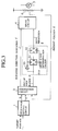
- FIG. 3 is a block diagram showing the arrangement of the first embodiment of the present invention.
- a motor 5 for moving a control object (not shown) is arranged, and a PBR 6 serving as a position detection circuit detects a present position of the control object moved by the motor 5, and outputs a present position signal d to a comparison circuit 2 as a voltage value.
- a stop range setting circuit 1 sets the upper and lower limit values of a stop range of the control object having a width predetermined with a target position of an input target position signal a in the center, and outputs an upper limit value signal b and a lower limit value signal c as voltage values to the comparison circuit 2 serving as a comparator circuit.
- the comparison circuit 2 has the same arrangement as that of the comparison circuit shown in FIG. 1, and compares the upper limit value signal b and the lower limit value signal c from the stop range setting circuit 1 with the present position signal d from the PBR 6.
- the comparison circuit 2 determines that the control object is not within the range of the upper and lower limit values and out of the stop range, the comparison circuit 2 outputs a out-of-stop range signal e which goes to H , and a rotating direction indication signal f serving as a drive direction indication signal.
- a drive start determination circuit 3 is arranged between the comparison circuit 2 and a drive circuit 4 for driving the motor 5.
- the rotating direction indication signal f is input to the drive circuit 4, and the out-of-stop range signal e is input to the drive start determination circuit 3.
- the drive start determination circuit 3 is constituted by a first flip-flop 31 and a second flip-flop 32 which are connected in series with each other, and an inverter 33.
- the out-of-stop range signal e from the comparison circuit 2 is input to an input terminal D of the first flip-flop 31, and an output from the first flip-flop 31 serves as an input signal of the second flip-flop 32.
- the out-of-stop range signal e is inverted by the inverter 33, and the inverted signal is input to reset terminals R of the first and second flip-flops 31 and 32.
- the out-of-stop range signal e is sampled by the first flip-flop 31 using a clock CLK, and an output from the second flip-flop 32 of the final stage is output to the drive circuit 4 as a drive permission signal g .
- Forward rotation, reverse rotation, and stop of the motor 5 are performed by the drive circuit 4 on the basis of the drive permission signal g from the drive start determination circuit 3 and the rotating direction indication signal f from the comparison circuit 2.
- the clock CLK is input twice or more times while the out-of-stop range signal e is at H level (t15 and t16).
- the first flip-flop 31 samples the out-of-stop range signal e .
- the output i from the first flip-flop 31 is sampled by the second flip-flop 32, and the drive permission signal g goes to H as shown in (d).
- the drive circuit 4 When the drive circuit 4 receives the drive permission signal g at t16, the drive circuit 4 rotates the motor 5 in a rotating direction indicated by the rotating direction indication signal f .
- the first flip-flop 31 and the second flip-flop 32 are reset. More specifically, if the out-of-stop range signal e does not keep H level for two or more clocks, an output from the second flip-flop 32, i.e., the drive permission signal g shown in (d), does not go to H .
- the drive circuit can be prevented from instantaneously repeating an ON/OFF operation due to external noise.
- the drive circuit is not influenced by the noise. Since the control object does not move unless the out-of-stop range signal is continuously output, the control object does not go out of the stop range.
- stop range need not be extended, stop precision is not degraded, and no hunching occurs. There is no probability of generating a foreign sound caused by repetitive fine movement of the control object within the stop range.
- a latch circuit may be used in place of the plurality of flip-flops.
- FIG. 5 is a block diagram showing the arrangement of the second embodiment of the present invention.
- a drive start determination circuit 7 constituted by an analog circuit is used in place of the drive start determination circuit 3 constituted by a digital circuit in the first embodiment.
- the drive start determination circuit 7 comprises a time constant circuit constituted by a resistor 71 and a capacitor 72; a charge/short-circuiting circuit constituted by a transistor 73 connected to the connection point between the resistor 71 and the capacitor 72 and an inverter 74 for inverting an out-of-stop range signal to input the inverted signal to the gate of the transistor 73; and a comparator 76.
- a charge/short-circuiting circuit charges the capacitor 72 when an out-of-stop range signal e is at H level, and short-circuits the capacitor 72 when the out-of-stop range signal e is at L .
- the arrangement of the second embodiment is the same as that of the first embodiment shown in FIG. 3 except for the drive start determination circuit 7.
- the drive permission signal g is output, and the drive circuit 4 rotates the motor 5 in a rotating direction indicated by the rotating direction indication signal f .
- the out-of-stop range signal e goes to L before the terminal voltage j reaches the reference voltage v1 , the transistor 73 is turned on, and the terminal voltage j of the capacitor 72 becomes almost 0 volt by short-circuiting. For this reason, the drive permission signal g is not output. More specifically, if the out-of-stop range signal e does not keep H level in the period of time T1 from when the charging of the capacitor 72 is started to when the terminal voltage j reaches the reference voltage v1 , the drive permission signal g is not output.
- the drive circuit can be prevented from instantaneously repeating an ON/OFF operation due to external noise.
- the motor 5 is driven.
- a predetermined period of time i.e., at least the period of time from when the charging of the capacitor 72 is started to when the terminal voltage of the capacitor 72 reaches the reference voltage.
- FIG. 7 is a block diagram showing the arrangement of the third embodiment of the present invention.
- a drive continuing circuit is arranged between a comparison circuit and a drive circuit in place of the drive start determination circuit in the first embodiment.
- a drive continuing circuit 8 comprises a latch circuit 81 which has a set input terminal S which is given a priority and a reset input terminal R , and a time constant circuit constituted by a resistor 82 and a capacitor 83.
- the drive continuing circuit 8 further comprises a charge/short-circuiting circuit constituted by a transistor 85 connected to the connection point between the resistor 82 and the capacitor 83 and an inverter 86 for inverting an output from the latch circuit 81 to input the inverted output to the gate of the transistor 85; and a comparator 88 for comparing a terminal voltage k of the capacitor 83 with a reference voltage v2 calculated by a partial voltage ratio of resistors 89 and 90 to output H when the capacitor terminal voltage k is higher than the reference voltage v2 .
- a out-of-stop range signal e from the comparison circuit 2 is input to the sat input terminal S of the latch circuit 81, and an output m from the comparator 88 is input to the reset terminals R .
- an initializing signal z of 1 pulse is input, and the initial state of an output from the latch circuit 81 is set at L level.
- the output from the latch circuit 81 is input to the drive circuit 4 as a drive permission signal g .
- the transistor 85 Since an output from the latch circuit 81 is at L level in an initial state, the transistor 85 is in an ON state. Therefore, the terminal voltage k of the capacitor 83 is 0 volt, and the output signal m from the comparator 88 is at L level.
- the transistor 85 since the output from the latch circuit 81 is inverted by the inverter 86 and applied to the transistor 85, the transistor 85 is turned off. In this manner, charging of the capacitor 83 is started, the terminal voltage k of the capacitor 83 increases with time as shown in (b). When the terminal voltage k of the capacitor 83 reaches the reference voltage v2 , the output signal m from the comparator 88 goes to H as at times t32 and t34 in (c), and the output signal m is input to the reset terminal R of the latch circuit 81.
- the drive permission signal g in (d) necessarily keeps H level at least from rising of the out-of-stop range signal to rising of the output m of the comparator 88, that is, for a predetermined period of time determined by an output from the time constant circuit constituted by the resistor 82 and the capacitor 83 and the reference voltage v2 .
- a predetermined period of time T2 is set to be a period of time which is long enough to start the motor 5 and in which a displacement of the control object with respect to the stop range is sufficiently small.
- the motor 5 when the motor 5 is started once, the motor 5 must be continuously driven in the period of time T2 regardless of the state of the out-of-stop range signal e .
- the latch circuit 81 is designed in such a way that the set input terminal is given a priority. For this reason, when the out-of-stop range signal e is at H level, even if the signal output from the comparator 88 and serving as a reset signal is at H level, the drive permission signal g does not go to L so long as the out-of-stop range signal e is at H level. When the out-of-stop range signal e falls later (time t35), the drive permission signal g goes to L , and the drive circuit 4 stops rotation of the motor 5.
- the motor 5 when the motor 5 is driven once, the motor 5 must be continuously driven at least in the predetermined period of time T2 by the drive continuing circuit 8 regardless of the out-of-stop range signal e . Therefore, the drive circuit can be prevented from instantaneously repeating an ON/OFF operation due to external noise.
- the control object when the control object is close to a boundary outside of the stop range, even if noise which drops the out-of-stop range signal is inserted into an output from the PBR after the drive circuit is turned on on the basis of the out-of-stop range signal, the motor is necessarily rotated within a predetermined period of time without receiving the influence of the noise. For this reason, the control object can be rapidly and certainly set within the stop range.
- the predetermined period of time T2 serving as the minimum drive time is set to be a period of time which is long enough to start the motor and in which a displacement of the control object with respect to the stop range is sufficiently small. For this reason, when the control object is within the stop range, even if noise is inserted into the output from the PBR 6 to raise the out-of-stop range signal e and start rotation of the motor 5, there is no chance that the control object unexpectedly go out of the stop range.
- time setting by the analog circuit has the following advantage. That is, the motor can be certainly stopped even if supply of an external clock is stopped by a malfunction.
- FIG. 9 is a block diagram showing the arrangement of the fourth embodiment of the present invention.
- the drive start determination circuit used in the second embodiment and the drive continuing circuit used in the third embodiment are arranged between a comparison circuit and a drive circuit.
- a drive start determination circuit 7 receives a out-of-stop range signal e from a comparison circuit 2 as an input to output a drive start signal g1 from a comparator 76 (see FIG. 5).
- a drive continuing circuit 8 inputs the drive start signal g1 from the drive start determination circuit 7 to a set input terminal S of a latch circuit 81 (see FIG. 7), and outputs an output from the latch circuit 81 to a drive circuit 4 as a drive permission signal g2 .
- the remaining arrangement of this embodiment is the same as the arrangement of the first embodiment.
- the drive start determination circuit 7 determines that the out-of-stop range signal e is continuously output for at least a predetermined period of time
- the drive start determination circuit 7 outputs the drive start signal g1 to the drive continuing circuit 8.
- the drive continuing circuit 8 receives the drive start signal g1
- the drive continuing circuit 8 outputs the drive permission signal g2 to the drive circuit 4, and the drive circuit starts driving of the motor 5.
- the motor is continuously driven for at least a predetermined minimum drive time regardless of the state of the drive start signal g1 .
- the drive start signal g1 does not go to H (t42).
- the drive continuing circuit 8 outputs the drive permission signal g2 in response to H level of the drive start signal g1 .
- the drive permission signal g2 keeps H level for at least a predetermined minimum drive time T4 as at times t44 to t46 regardless of the state of the drive start signal g1 . After the minimum drive time T4 has elapsed, when the drive start signal g1 goes to L , the outputting operation of the drive permission signal g2 is stopped (time t49).
- a drive condition determination circuit is constituted by the drive start determination circuit 7 and the drive continuing circuit 8.
- driving of the motor is started only when the out-of-stop range signal e output from the comparison circuit keeps H level for at least the predetermined period of time T3. Then, once the driving is started, the motor is continuously driven for the predetermined period of time T4 without any conditions. Thereafter, when the control object is located within the stop range to set the out-of-stop range signal at L level, outputting of a drive permission signal is stopped.
- the control object when the control object is close to a boundary outside the stop range, even if noise which drops the out-of-stop range signal is inserted into an output from the PBR after the drive circuit is turned on on the basis of the out-of-stop range signal, the motor is necessarily rotated within a predetermined period of time without receiving the influence of the noise. For this reason, the control object can be rapidly and certainly set within the stop range.
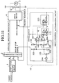
- FIG. 11 is a block diagram showing the arrangement of the fifth embodiment of the present invention.
- a drive condition determination circuit which integrally performs the functions of these circuits is arranged.
- a drive condition determination circuit 10 receives an out-of-stop range signal e from a comparison circuit 2 and outputs a drive permission signal g to a drive circuit 4.
- the drive condition determination circuit 10 comprises a time constant circuit constituted by a resistor 101 and a capacitor 102; a charge/short-circuiting circuit constituted by a transistor 103 connected to the connection point between the resistor 101 and the capacitor 102 and a NOR gate 104 connected to the gate of the transistor 103; and first and second comparators 106 and 107 for comparing a terminal voltage n of the capacitor 102 with predetermined reference voltages v3 and v4 , respectively.
- the NOR gate 104 receives an out-of-stop range signal e and a drive permission signal g as inputs. When both the out-of-stop range signal e and the drive permission signal g are at L level, the NOR gate 104 turns on the transistor 103 to short-circuit the capacitor 102.
- Resistors 108, 109, and 110 which are connected in series with each other are arranged to define the reference voltages of the first and second comparators 106 and 107, and a first reference voltage v3 and a second reference voltage v4 based on partial voltage ratios at respective connection points are input to the first and second comparators 106 and 107, respectively.
- the first reference voltage v3 and the second reference voltage v4 are set to satisfy a condition v3 ⁇ v4 .
- the first comparator 106 outputs H when the terminal voltage n of the capacitor 102 is higher than the first reference voltage v3
- the second comparator 107 outputs H when the terminal voltage of the capacitor 102 is higher than the second reference voltage v4 .
- the drive condition determination circuit 10 further comprises a first latch circuit 112 connected to the first comparator 106 and a second latch circuit 113 connected to the second comparator 107.
- the first latch circuit 112 is a reset priority circuit having an output p from the first comparator 106 as a set input and a signal obtained by inverting the out-of-stop range signal e by an inverter 114 as a reset input.
- the second latch circuit 113 is a set priority circuit having an output r from the first latch circuit 112 as a set input and an output q from the second comparator 107 as a reset input. An output from the second latch circuit 113 is used as the drive permission signal g .
- An initializing signal of 1 pulse is input to the first and second latch circuits 112 and 113 when a power supply is turned on, so that the initial state of each output is set at L level.
- the remaining arrangement is the same as that in the first embodiment.
- the output p from the first comparator 106 shown in (c) does not go to H . More specifically, unless the out-of-stop range signal e keeps H level for at least a first predetermined period of time T5 from when charging of the capacitor 102 is started to when the terminal voltage reaches the first reference voltage v3 , the output p from the first comparator 106 does not go to H .
- the out-of-stop range signal e keeps H level, and the terminal voltage n of the capacitor 102 reaches the first reference voltage v3 , the output p from the first comparator 106 goes to H , and the output r from the first latch circuit 112 shown in (e) is set at H level (times t54 and t58).
- an output from the second latch circuit 113 i.e., the drive permission signal g shown in (f) is set at H level.
- the drive circuit 4 which receives the drive permission signal g drives the motor 5 in a direction indicated by a rotating direction indication signal f (t54 and t58).
- the drive circuit 4 stops driving of the motor 5.
- the transistor 103 is turned on, and the terminal voltage n of the capacitor 102 returns to almost 0 volt.
- the drive permission signal g necessarily keeps H level regardless of the state of the out-of-stop range signal e for a second predetermined period of time T6 from when the output p from the first comparator 106 rises to when the output q from the second comparator 107 rises.
- the output q from the second comparator 107 goes to H at time (time t59) at which the capacitor terminal voltage n exceeds the second reference voltage v4 , and a reset signal is input to the second latch circuit 113.
- the second latch circuit 113 has a set input terminal which is given a priority, and the output r from the first latch circuit 112 serving as a setting signal keeps H . For this reason, the drive permission signal g keeps H level.
- the out-of-stop range signal e is output due to external noise
- the out-of-stop range signal e is not continuously output for at least the predetermined period of time T5.
- the output r from the first comparator 106 does not go to H due to an output generated by noise. Therefore, the drive permission signal g keeps L level.
- the drive circuit can be prevented from instantaneously repeating an ON/OFF operation due to external noise, and the same effect as described in the previous embodiment can be obtained.
- the present invention is not limited to a control apparatus in which a control object such as a lever is rotated about one point, and is also applied to positioning in a control apparatus for linearly displacing a control object.
- a drive start determination circuit is arranged to output a drive permission signal to the drive circuit when the out-of-stop range signal is continuously output for a first predetermined period of time. For this reason, even if external noise is inserted into the present position signal or the like, the drive circuit does not instantaneously repeat an ON/OFF operation, or noise is not generated by repeating the ON/OFF operation.
- a set stop range need not be extended, and a filter is not required. For this reason, the positioning apparatus of the present invention is free from degradation of stop precision or an increase in overrunning amount.
- a drive continuing circuit is arranged in place of the drive start determination circuit, and a drive permission signal is continuously output for at least a second predetermined period of time after the out-of-stop range signal has been output.
- the positioning apparatus is not influenced by external noise, and the motor is necessarily drive for a predetermined period of time after driving has been started on the basis of the out-of-stop range signal. For this reason, the control object can be rapidly and certainly set within the stop range without obstructing the driving of the motor.
- a drive condition determination circuit outputs a drive permission signal when the out-of-stop range signal is continuously output for at least the first predetermined period of time, and the drive permission signal is continuously output for at least the second predetermined period of time after outputting of the drive permission signal has been started. For this reason, even if external noise is inserted into the present position signal or the like, the drive circuit does not instantaneously repeat an ON/OFF operation, or motor drive started on the basis of the out-of-stop range signal is prevented from being obstructed.
Landscapes
- Engineering & Computer Science (AREA)
- Human Computer Interaction (AREA)
- Manufacturing & Machinery (AREA)
- Physics & Mathematics (AREA)
- General Physics & Mathematics (AREA)
- Automation & Control Theory (AREA)
- Power Engineering (AREA)
- Stopping Of Electric Motors (AREA)
- Control Of Position Or Direction (AREA)
- Control Of Electric Motors In General (AREA)
Applications Claiming Priority (3)
| Application Number | Priority Date | Filing Date | Title |
|---|---|---|---|
| JP31467795A JP3280556B2 (ja) | 1995-11-08 | 1995-11-08 | 位置決め装置 |
| JP314677/95 | 1995-11-08 | ||
| JP31467795 | 1995-11-08 |
Publications (3)
| Publication Number | Publication Date |
|---|---|
| EP0773488A2 true EP0773488A2 (fr) | 1997-05-14 |
| EP0773488A3 EP0773488A3 (fr) | 1998-01-07 |
| EP0773488B1 EP0773488B1 (fr) | 2002-06-05 |
Family
ID=18056228
Family Applications (1)
| Application Number | Title | Priority Date | Filing Date |
|---|---|---|---|
| EP96117877A Expired - Lifetime EP0773488B1 (fr) | 1995-11-08 | 1996-11-07 | Appareil de positionnement |
Country Status (5)
| Country | Link |
|---|---|
| US (1) | US6020708A (fr) |
| EP (1) | EP0773488B1 (fr) |
| JP (1) | JP3280556B2 (fr) |
| KR (1) | KR100242098B1 (fr) |
| DE (1) | DE69621560T2 (fr) |
Cited By (3)
| Publication number | Priority date | Publication date | Assignee | Title |
|---|---|---|---|---|
| EP1154341A3 (fr) * | 2000-05-12 | 2002-11-13 | Seiko Epson Corporation | Dispositif de commande d'entraínement, méthode de commande de mécanisme d'entraínement et milieu de stockage de données contenant un programme d'ordinateur |
| EP1479548A1 (fr) * | 2003-05-22 | 2004-11-24 | Calsonic Kansei Corporation | Dispositif de commande de servomoteur d'un véhicule automobile |
| EP1480094A3 (fr) * | 2003-05-22 | 2008-02-13 | Calsonic Kansei Corporation | Dispositif de commande de servomoteur |
Families Citing this family (6)
| Publication number | Priority date | Publication date | Assignee | Title |
|---|---|---|---|---|
| US20040232864A1 (en) * | 2003-05-23 | 2004-11-25 | Hideki Sunaga | Apparatus for controlling motor |
| JP4651298B2 (ja) | 2004-04-08 | 2011-03-16 | 三菱電機株式会社 | 周波数自動補正pll回路 |
| KR100588415B1 (ko) * | 2004-06-17 | 2006-06-09 | 동아전기부품 주식회사 | 차량용 공조기의 액츄에이터 제어방법 및 그 장치 |
| US12234701B2 (en) | 2022-09-12 | 2025-02-25 | Saudi Arabian Oil Company | Tubing hangers and related methods of isolating a tubing |
| US12188328B2 (en) | 2023-05-15 | 2025-01-07 | Saudi Arabian Oil Company | Wellbore back pressure valve with pressure gauge |
| US12442257B2 (en) | 2023-05-23 | 2025-10-14 | Saudi Arabian Oil Company | Completing and working over a wellbore |
Family Cites Families (13)
| Publication number | Priority date | Publication date | Assignee | Title |
|---|---|---|---|---|
| US3727120A (en) * | 1971-07-01 | 1973-04-10 | Westinghouse Canada Ltd | Width controlled samplier pulsing a sample-hold thereby effecting a low-pass filter for a sample-data servo |
| DE3063844D1 (en) * | 1979-04-27 | 1983-07-28 | Nec Corp | Servo control system operable on digital basis |
| US4300080A (en) * | 1979-10-22 | 1981-11-10 | Sperry Corporation | Power driver control circuit for servo actuator |
| JPS59136815A (ja) * | 1983-01-27 | 1984-08-06 | Nissan Motor Co Ltd | ロボツトの駆動制御装置 |
| JPS6054022A (ja) * | 1983-09-01 | 1985-03-28 | Mitsubishi Electric Corp | ロボツトの駆動制御装置 |
| JPS6181865A (ja) * | 1984-08-16 | 1986-04-25 | Honda Motor Co Ltd | 電磁型倍力装置 |
| JPH054407Y2 (fr) * | 1987-07-18 | 1993-02-03 | ||
| JPH0742822Y2 (ja) * | 1987-07-20 | 1995-10-04 | サンデン株式会社 | 自動車用空調装置 |
| JP2572635B2 (ja) * | 1988-07-04 | 1997-01-16 | 株式会社ゼクセル | 自動車用空調装置のエアミクスドア制御装置 |
| US4902953A (en) * | 1988-08-19 | 1990-02-20 | Kraft David W | Motorized window blind electrical actuator |
| JP2704009B2 (ja) * | 1989-10-19 | 1998-01-26 | マツダ株式会社 | 自動車の空調制御装置 |
| US5132602A (en) * | 1990-10-02 | 1992-07-21 | Calsonic International, Inc. | Actuator positioning apparatus |
| JP2735153B2 (ja) * | 1995-03-03 | 1998-04-02 | 工業技術院長 | 精密位置制御装置及び精密位置制御方法 |
-
1995
- 1995-11-08 JP JP31467795A patent/JP3280556B2/ja not_active Expired - Lifetime
-
1996
- 1996-11-07 KR KR1019960052592A patent/KR100242098B1/ko not_active Expired - Lifetime
- 1996-11-07 EP EP96117877A patent/EP0773488B1/fr not_active Expired - Lifetime
- 1996-11-07 DE DE69621560T patent/DE69621560T2/de not_active Expired - Lifetime
- 1996-11-08 US US08/746,348 patent/US6020708A/en not_active Expired - Lifetime
Non-Patent Citations (1)
| Title |
|---|
| None |
Cited By (5)
| Publication number | Priority date | Publication date | Assignee | Title |
|---|---|---|---|---|
| EP1154341A3 (fr) * | 2000-05-12 | 2002-11-13 | Seiko Epson Corporation | Dispositif de commande d'entraínement, méthode de commande de mécanisme d'entraínement et milieu de stockage de données contenant un programme d'ordinateur |
| US6848061B2 (en) | 2000-05-12 | 2005-01-25 | Seiko Epson Corporation | Drive mechanism control device and method, driving operation confirmation method for a drive mechanism, and programs for implementing the methods |
| EP1479548A1 (fr) * | 2003-05-22 | 2004-11-24 | Calsonic Kansei Corporation | Dispositif de commande de servomoteur d'un véhicule automobile |
| US7061202B2 (en) | 2003-05-22 | 2006-06-13 | Calsonic Kansei Corporation | Automobile servomotor controller |
| EP1480094A3 (fr) * | 2003-05-22 | 2008-02-13 | Calsonic Kansei Corporation | Dispositif de commande de servomoteur |
Also Published As
| Publication number | Publication date |
|---|---|
| JP3280556B2 (ja) | 2002-05-13 |
| DE69621560T2 (de) | 2002-09-26 |
| EP0773488B1 (fr) | 2002-06-05 |
| KR970031214A (ko) | 1997-06-26 |
| KR100242098B1 (ko) | 2000-02-01 |
| DE69621560D1 (de) | 2002-07-11 |
| US6020708A (en) | 2000-02-01 |
| EP0773488A3 (fr) | 1998-01-07 |
| JPH09134218A (ja) | 1997-05-20 |
Similar Documents
| Publication | Publication Date | Title |
|---|---|---|
| US6020708A (en) | Positioning apparatus | |
| US7525878B2 (en) | Time measuring circuit with pulse delay circuit | |
| US7728540B2 (en) | Motor driving circuit | |
| EP0158512A2 (fr) | Circuit de remise à l'état initial | |
| EP3531556A1 (fr) | Dispositif à semiconducteur, système à semiconducteur et système de commande | |
| EP1187306A2 (fr) | Appareil et méthode pour réguler la vitesse de rotation de rotor d'un moteur sans balai | |
| US6580242B2 (en) | Entrapment detection device of opening/closing member | |
| JPH05166201A (ja) | 光ディスクのトラック検索装置 | |
| US20040174206A1 (en) | Voltage detecting circuit | |
| JP6847181B1 (ja) | 車載制御装置 | |
| US5231343A (en) | Driving apparatus for stepping motor capable of restraining motor noise | |
| US5065047A (en) | Digital circuit including fail-safe circuit | |
| US5856733A (en) | Positioning apparatus | |
| JP2001338810A (ja) | ソレノイド駆動回路及びその使用方法 | |
| JPH08186881A (ja) | 多重通信装置 | |
| EP4112381A1 (fr) | Dispositif de mise à niveau de phare et procédé de mise à niveau d'un phare de véhicule | |
| JP3329142B2 (ja) | 位置検出回路 | |
| CN111600516B (zh) | 一种用于电机的驱动控制系统、汽车和控制方法 | |
| CN212278147U (zh) | 一种电机驱动装置和汽车 | |
| JP3865567B2 (ja) | サンルーフ制御装置 | |
| US5819122A (en) | Camera | |
| JPH0315287A (ja) | サーボ回路 | |
| CN115425947A (zh) | 一种数字脉冲滤波电路、芯片 | |
| KR100973698B1 (ko) | 액츄에이터 제어시스템에 포함되는 리미트 스위치 회로 | |
| SU1667215A1 (ru) | Устройство дл регулировани скорости электродвигател |
Legal Events
| Date | Code | Title | Description |
|---|---|---|---|
| PUAI | Public reference made under article 153(3) epc to a published international application that has entered the european phase |
Free format text: ORIGINAL CODE: 0009012 |
|
| 17P | Request for examination filed |
Effective date: 19961107 |
|
| AK | Designated contracting states |
Kind code of ref document: A2 Designated state(s): DE FR GB |
|
| PUAL | Search report despatched |
Free format text: ORIGINAL CODE: 0009013 |
|
| AK | Designated contracting states |
Kind code of ref document: A3 Designated state(s): DE FR GB |
|
| 17Q | First examination report despatched |
Effective date: 19990630 |
|
| GRAG | Despatch of communication of intention to grant |
Free format text: ORIGINAL CODE: EPIDOS AGRA |
|
| GRAG | Despatch of communication of intention to grant |
Free format text: ORIGINAL CODE: EPIDOS AGRA |
|
| GRAH | Despatch of communication of intention to grant a patent |
Free format text: ORIGINAL CODE: EPIDOS IGRA |
|
| GRAH | Despatch of communication of intention to grant a patent |
Free format text: ORIGINAL CODE: EPIDOS IGRA |
|
| GRAA | (expected) grant |
Free format text: ORIGINAL CODE: 0009210 |
|
| AK | Designated contracting states |
Kind code of ref document: B1 Designated state(s): DE FR GB |
|
| REG | Reference to a national code |
Ref country code: GB Ref legal event code: FG4D |
|
| REF | Corresponds to: |
Ref document number: 69621560 Country of ref document: DE Date of ref document: 20020711 |
|
| ET | Fr: translation filed | ||
| PLBE | No opposition filed within time limit |
Free format text: ORIGINAL CODE: 0009261 |
|
| STAA | Information on the status of an ep patent application or granted ep patent |
Free format text: STATUS: NO OPPOSITION FILED WITHIN TIME LIMIT |
|
| 26N | No opposition filed |
Effective date: 20030306 |
|
| REG | Reference to a national code |
Ref country code: FR Ref legal event code: ST |
|
| REG | Reference to a national code |
Ref country code: FR Ref legal event code: RN |
|
| REG | Reference to a national code |
Ref country code: FR Ref legal event code: FC |
|
| REG | Reference to a national code |
Ref country code: FR Ref legal event code: PLFP Year of fee payment: 20 |
|
| PGFP | Annual fee paid to national office [announced via postgrant information from national office to epo] |
Ref country code: DE Payment date: 20151103 Year of fee payment: 20 Ref country code: GB Payment date: 20151104 Year of fee payment: 20 |
|
| PGFP | Annual fee paid to national office [announced via postgrant information from national office to epo] |
Ref country code: FR Payment date: 20151008 Year of fee payment: 20 |
|
| REG | Reference to a national code |
Ref country code: DE Ref legal event code: R071 Ref document number: 69621560 Country of ref document: DE |
|
| REG | Reference to a national code |
Ref country code: GB Ref legal event code: PE20 Expiry date: 20161106 |
|
| PG25 | Lapsed in a contracting state [announced via postgrant information from national office to epo] |
Ref country code: GB Free format text: LAPSE BECAUSE OF EXPIRATION OF PROTECTION Effective date: 20161106 |