EP0773530A2 - Player apparatus - Google Patents
Player apparatus Download PDFInfo
- Publication number
- EP0773530A2 EP0773530A2 EP96116952A EP96116952A EP0773530A2 EP 0773530 A2 EP0773530 A2 EP 0773530A2 EP 96116952 A EP96116952 A EP 96116952A EP 96116952 A EP96116952 A EP 96116952A EP 0773530 A2 EP0773530 A2 EP 0773530A2
- Authority
- EP
- European Patent Office
- Prior art keywords
- rod
- violin
- vibration
- bridge
- voice coil
- Prior art date
- Legal status (The legal status is an assumption and is not a legal conclusion. Google has not performed a legal analysis and makes no representation as to the accuracy of the status listed.)
- Withdrawn
Links
Images


Classifications
-
- H—ELECTRICITY
- H04—ELECTRIC COMMUNICATION TECHNIQUE
- H04R—LOUDSPEAKERS, MICROPHONES, GRAMOPHONE PICK-UPS OR LIKE ACOUSTIC ELECTROMECHANICAL TRANSDUCERS; ELECTRIC HEARING AIDS; PUBLIC ADDRESS SYSTEMS
- H04R1/00—Details of transducers, loudspeakers or microphones
- H04R1/42—Combinations of transducers with fluid-pressure or other non-electrical amplifying means
-
- G—PHYSICS
- G10—MUSICAL INSTRUMENTS; ACOUSTICS
- G10F—AUTOMATIC MUSICAL INSTRUMENTS
- G10F1/00—Automatic musical instruments
- G10F1/16—Stringed musical instruments other than pianofortes
Definitions
- the present invention relates to a player apparatus for a high-fidelity reproduction of original sounds with the use of a stringed instrument such as a violin.
- a speaker which comprises a bobbin having a cone-shaped vibration plate, a voice coil wound around one end of the bobbin and a magnet circuit combined with the voice coil.
- the conventional speaker has had a problem such that unless the CG of the vibration plate is consistent with the driving center of the voice coil, the vibration plate would not vibrate properly, so that the original speech can no longer be precisely reproduced.
- Japanese Patent Examined Publication No.57-56279 an apparatus which controls the amount of air entering from both sides of the central partition wall of a cylindrical voice coil in order to arbitrarily adjust the position of the vibration plate or the voice coil.
- this type of the conventional speaker would reproduce speech through a vibration plate such as a cone paper, which, as a result, could not reproduce as vivid speech as the original ones. Consequently, there have been always some dissatisfaction at the audience end that with the conventional highest-grade speakers, yet they cannot listen to as vivid a musical performance as if they were present at a live concert.
- the present invention is remarkably characterized by substituting the resonance mechanism of stringed instruments, more specifically so-called violin group instruments including a violin, a viola, a cello and a contrabass (or double bass) for the vibration plate of the conventional speaker.
- a player apparatus of the invention is structured by a driving coil for converting speech current into mechanical vibration, a rod-like member of which the proximal end is connected to a vibrating part of the driving coil and one of the stringed instruments included in violin group having its bridge connected to the distal end of the rod-like member.
- the mechanical vibration from the driving coil is propagated across the rod-like member to the bridge of the stringed instrument such as violin, whereby the speech can be reproduced through a resonating body of the stringed instrument as if the instrument were actually played.
- the aforesaid driving coil comprises a magnet circuit and a voice coil which vibrates due to electromagnetic induction by the magnet circuit, said voice coil desirably being provided with a damper for controlling radial vibration.
- a damper for controlling radial vibration.
- the aforesaid magnet circuit constructing the driving coil may be provided with alnico-based magnet material rather than ferite-based one.
- Alnico-based magnet material generally indicates excellent magnetic property, which is incorporated into the magnet circuit in order for the driving coil to precisely convert speech signals into mechanical vibration. In that case, owing to a plurality of dampers for control of the radial vibration of the voice coil, you do not have to prescribe the precise configuration or material of the aforesaid rod-like member.
- the rod-like member may be connected to the vibration part so that the front-to-back vibration of the voice coil may be propagated to the axial direction of the rod-like member, while the rod-like member in turn be connected to the bridge so as to propagate the axial vibration of the rod-like member to the side-direction of the bridge.
- the radial vibration of the voice coil being controlled by the damper(s)
- only the front-to-back vibration of the voice coil can be propagated to the side-direction of the bridge, thereby effecting the vivid reproduction of speech which is heard as if the strings were actually rubbed against a bow.
- the aforesaid rod-like member is, preferably, a metallic rod having a Pernambuco lumber combined therewith.
- Pernambuco is a natural wood which is widely recognized as a raw material of a support member of a bow for rubbing the strings of a stringed instrument.
- the Pernambuco lumber constructing a part of the rod-like member can effectively absorb undesirable resonant vibration unique to a metallic rod, while beautiful and serene speech can be reproduced out of a body of the stringed instrument as if the strings were actually rubbed against a bow.
- Fig.1 through Fig .4 show a first embodiment of the present invention, of which Figs.1 to 3 show a general structure of the apparatus.
- Reference numeral 1 designates a pedestal, 2 a casing provided at one side thereof, all of which are constructed by assembling wooden plates. Inside the casing 2 is provided a magnet circuit 7 comprising a bottom plate 4 having a center pole 3, an upper plate 5 and an annular magnet 6 provided therebetween, said magnet circuit 7 being supported by a metallic frame 8.
- Reference numeral 9 designates a voice coil which is able to vibrate within a magnetic gap 10 of the magent circuit 7.
- the conductor coil 9A When a speech current flows through a coil 9A of the voice coil 9 placed in a magentic field of the magentic circuit 7, the conductor coil 9A is displaced due to an electromagnetic induction, thus vibrating the voice coil 9 as a whole.
- the aforesaid voice coil 9 and the magnetic circuit 7 construct a driving coil 11 for converting a speech current into a mechanical vibration.
- Onto the distal end of the voice coil 9 is mounted a cylindrical cap 12 as an vibrating part of the driving coil 11, thus propagating the vibration outwards.
- the diameter of the cap 12 is set at 53 mm.
- Reference numeral 13 designates a damper which serves to support the voice coil 9 coaxially around the center pole 3, and thus to control unnecessary radial vibration of the voice coil 9.
- an existing cone-type speaker is used with the vibrating plate thereof being removed therefrom, while aforesaid annular magnet 6 is made of ferite-based magnet material.
- Reference numeral 21 is a rod-like member or a rod extending from the center of the cap 12 toward the outside of the casing 2.
- the rod 21 comprises a first rod member 22 having its proximal end attached to the center of the cap 12, a second rod member 24 which is connected to the distal end of the first rod member 22 by a screw 23 and an interposing body 26 connected to the distal end of the rod member 24 by another screw 25.
- the interposing body 26 comprises a first fixing member 27 which is tabular and attached to the second rod member 24 by the screw 25, and a second fixing member 29 which is removably mounted to the first fixing memeber 27 by a screw 28.
- a non-slip members 30 such as a papersand, which can ensure the contact of the interposing member 26 with a hereinbelow-described bridge 45.
- the mechanical vibration from the rod 21 can be precisely propagated to the bridge 45.
- reference numeral 40 designates a resilient piece which is U-shaped to support ribs 41 of a stringed instrument included in violin group.
- a violin 42 is fitted into the resilient piece 40 with the scroll 43 thereof being positioned upside.
- the body 49 as a resonating mechanism is provided with a table 46 or so-called a belly having the bridge 45 mounted thereon, a rear table 47 spaced relative to the table 46 and a sound post 48 for propagating the vibration from the bridge 45 to the rear table 47.
- the aforesaid resilient piece 40 is fixed to a movable table 51 which is slidable on the pedestal 1, while the casing 2 is able to be raised or lowered by revolving a volt 52. Accordingly, even with the use of other violins having slightly different configurations, the movable table 51 and the volt 52 can be adjusted so as to ensure the connecting of the bridge 45 with the distal end of the rod 21.
- the first rod member 22 of this embodiment is formed to a 7mm diameter, while the second rod member 24 thereof a 5mm diameter.
- the distance from the proximal end of the first rod member 22 to the point of contact between the interposing body 26 and the bridge 45 be set at 145 mm. This should apply to the case that the violin 42 is used as one of the stringed instruments included in violin group.
- Reference numerals 53a, 53b designate R-channel and L-channel output terminals of a stereo-amplifier 53 or the source of speech respectively, while 54 a pair of switches for supplying a speech current from each of the output terminals 53a, 53b to either stereo-speakers 55,56 or the casing 2.
- Reference numeral 57 designates a dummy resistance having the same value of resistance of 8 ohm as that of the stereo-speaker 55 or 56.
- the casing 2 contains thereinside a main switch 61, a coil 62a of a relay 62 and a neon lamp 63 as a display, which are connected to both terminals of a power supply plug 64.
- a point of contact 62b of the relay 62 for supplying a speech current from the output terminal 53a to the driving coil 11 is allowed to connect to between an external terminal 65 connected to the normally closed terminal 54a of said switch 54 and the driving coil 11.
- the speech current from the R-channel of the stereo-amplifier 53 is supplied to the driving coil 11 inside the casing 2.
- the speech current from the L-channel of the stereo-amplifier 53 may be supplied to the driving coil 11. Otherwise, the combined speech current from both the channels R and L may be supplied to the driving coil 11.
- the ribs 41 of the violin 42 are supported by the resilient piece 40, then the movable table 51 and the volt 52 are suitably adjusted for proper positioning so that the distal end of the second rod member 24 may be located in the neighborhood of the bridge 45 of the violin 42.
- the first fixing member 27 is attached to the distal end of the second rod member 24, thus sandwiching one side of the bridge 45 between the first fixing member 27 and the second fixing member 29.
- the speech current from the stereo-amplifier 53 is supplied across the switch 54 to the stereo-speakers 55 and 56, thereby reproducing sounds therefrom. This is the same as the existing well-known stereophonic system.
- the point of contact 62b of the relay 62 is switched so that the speech current from the R-channel of the stereo-amplifier 53 is supplied to the driving coil 11.
- the driving coil 11 converts the speech current into the mechanical vibration, it is propagated from the rod 21 to the bridge 45 of the violin 42, thus vibrating the body 49 of the violin 42 so as to reproduce sounds therefrom.
- This embodiment of the invention is featured by making use of the resonance mechanism of stringed instruments such as a violin, a viola, a cello, a contrabass and the like included in so-called violin group, instead of the vibration plate of the conventional speaker.
- the strings 44 are generally allowed to vibrate by rubbing the same against a bow made of horse-hair (now shown) coated with pine resin, then the vibration thus generated is propagated from the bridge 45 to the table 46, which is further propagated across the sound post 48 to the rear table 47 having a slightly different lower natural frequency (or fundamental frequecy) than the table 46.
- a musical sound unique to a stringed instrument such as the violin 42 is allowed to mainly come out of a pair of so-called f holes formed in the tale 46.
- the bridge plays a very important role that the side-vibration from the strings 44 is oriented to the direction defined at the right angles thereto.
- the inventor of the present invention has found out that if a mechanical vibration having a frequency equivalent to that developed by rubbing the strings 44 against a bow is given from external to the bridge 45, there can be reproduced a musical sound which is so close to a sound from the stringed instrument as actually played that one feels that the sound thus generated is beyond comparison with the conventional highest-grade speaker.
- the mechanical vibration from the driving coil 11 can be propagated from the rod 21 to the bridge 45 which supports the strings 44 of the violin 42, whereby a musical sound can be reproduced with a highest-fidelity out of the body 49 of the violin 42 as if the viloin 42 were actually played.
- the driving coil 11 is connected to the bridge 45 by the rod 21
- the present invention is advantageous because of the following requirement.
- a stringed instrument such as a violin is overhauled or newly facbricated, its resonating body 49 becomes or remains difficult to vibrate, so that any excellent sounds unique to the instrument cannot be obtained unless the instrument is continuously used for one or two months.
- the speech current is intentionally applied to the driving coil 11, thus enabling the instrument to display the full ability to generate the sounds as originally expected in a short period.
- a player apparatus of the invention is very advantageous in that it can be used as an aging apparatus of the violin 42 in addition to the aforesaid use as a player.
- the sound developed by musical instruments such as the violin 42 generally has a specific range of its fundamental frequency and other frequencies which are each an integrity times as high as the fundamental frequency. Therefore, it is desirable that the frequency components of the speech current should be as close to those of the sounds developed by the violin 42 as possible.
- the resonating body 49 of the violin 42 does generate real sounds. This is because that the frequency components of the recorded musical performance of the violin are approximately equal to those unique to the violin 42.
- the player apparatus of the invention can make use of other instruments included in violin group such as a viola, a cello, a contrabass and the like, thrum-type stringed instruments such as a guitar and a mandolin and even a cembalo, so that sounds comparatively close to the original sounds can be reproduced respectively.
- the present inventor found that Sonata with the violin and the piano can also be reproduced as vividly as the original performance.
- the violin 42 is replaced with a cello in this embodiment, the sound of the piano alone can also be reproduced well due to the difference in frequency components between the cello and the violin.
- the material of the rod 21 must be carefully chosen in order to propagate the mechanical vibration from the cap 12 of the drivig coil 11 with complete high-fidelity.
- the resilience, damping (internal friction), density, propagation velocity and natural frequency of the rod 21 must be taken into consideration.
- the table 46 made of a pine has the different fundamental frequency than that of the rear table 47 made of a maple, such that the adjustment of the table 46 at the musical scale ranging from C# to D and the rear table 47 from D to D# can assemble a violin which can generate excellent sounds.
- the fundamental frequency of the table 46 should range from 139 to 148 Hz (or C#3 to D3 at the musical scale), while that of the rear table 47 from 148 to 156 (or D3 to D#3 at the musical scale).
- the fundamental frequency of the rod 21 be out of the range from 139 to 156 Hz as defined by the above frequency ranges of the table 46 and rear table 47, even being inconsistent with either frequncies integrity times the above range.
- the distance from the proximal end of the first rod member 22 to the contact point between the interposing body 26 and the bridge 45 is set at 145 mm, and that the rod 21 is made of aluminium alloy alone, whereby there could be reproduced out of the body 49 of the violin 42 the sounds with the highest-fidelity.
- the damper 13 controlling the radial vibration of the voice coil 9
- the front-to-back vibration of the voice coil 9 alone can be propagated to the side direction of the bridge 45, thereby reproducing the sounds as vividly as if the strings 44 were actually rubbed against a bow.
- the driving coil 11 for use with the present embodiment can be obtained by removing the vibration plate from any exisiting speaker, without any needs of a particular structure. Accordingly, the fabrication of the appparatus will not be accompanied by any difficulty when it is actually designed. As the final quality of the sounds will also vary by replacing the violin 42 with another, the present apparatus can be effectively utilized for examining the quality of sounds which you can expect from the violin 42. Needless to say, you do not have to always use the built-in driving coil of the existing speaker for that of the invention.
- This embodiment relates to an improved type of the aforesaid rod 21 of a first embodiment.
- the rod-like member or the rod 21 of a second embodiment is so structured that an aluminium alloy rod 71 of 6mm diameter is connected to the center of the cap 12 of the driving coil 11, then to the distal end of the rod 71 is fittingly bonded a Pernambuco lumber 72, of which the distal end is then fixedly connected to the intreposing body 26 of a first embodiment by the screw 25. Further, the distance from the proximal end of the rod 71 to the contact point between the interposing body 26 and the bridge 45 is set at 145 mm.
- Other structures of a second embodiment are totally the same as those of a first embodiement.
- the Pernambuco lumber 72 as referred to in the above paragraph is a natural wood produced in Brazil, which is well-known to one skilled in the art as a preferred raw material for a supporting member of a bow against which the strings of the stringed instruments are rubbed. As a part of the rod 21 is constructed by a wood of the different nature to others, any undesirable resonant frequency of the natural frequency of the metallic rod 71 can be absorbed therein. Additionally, it is noted that the Pernambuco lumber 72 is said to be the most suited for generating the excellent sounds in drawing a bow against strings.
- the Pernambuco lumber 72 constructing a part of the rod 21 for propagation of the mechanical vibration to the bridge 45, there can be reproduced from the body 49 of the violin 42 as beautiful and serene sounds as if the bow were drawn against the strings with the Pernaumbuco lumber 72 being atached to the bow.
- the Pernambuco lumber 72 is usually used as a supporting member for a bow of not only the violin 42 but other stringed instruments included in violin group, ths same effect can be expected even in the case that other instruments than the violin 42 are used in the invention.
- the undesirable resonant frequency unique to the rod 71 can be effectively absorbed and thus can reproduce with high fidelity as beautiful and serene sounds as if a bow with the Pernumbuco lumber 72 were drawn against strings.
- the bottom plate 4 is allowed to extend outward relative to the annular magnet 6, while to front sides of the outer periphery of the bottom plate 4 are mounted double dampers 13 and 13A which are supported by an annular member 81.
- an annular member 81 like a first emboidment, there may be provided a single damper 13.
- the annular member 81 thus provided can make the aforesaid metallic frame 8 of a first embodiment unnecessary.
- the annular magnet 6 of this embodiment uses an alnico-based magnet material which indicates a larger magnetic flux density and thus a more excellent magnetic property.
- first rod member 22 constructing the rod 21 is made of hollow aluminium alloy
- first and second embodiments to precisely prescribe either the aforesaid distance from the proximal end of the first rod member 22 to the contact point between the interposing member 26 and the bridge 45, or the configuration and material of the first rod member 22. That results from the facts that the annular magnet 6 constructing the driving coil 11 has an excellent magnetic property and the plural dampers 13 and 13A can more effectively suppress the radial vibration of the voice coil 9.
- Other structures in this embodiment is totally the same as those of a first embodiment.
- the present invention should not be limited to the foregoing embodiments, but may be variously modified within a technical scope of the invention.
- the rod-like member or rod 21 may be suitably shaped otherwise, taking the properties of the various stringed instruments into consideration.
Landscapes
- Physics & Mathematics (AREA)
- Engineering & Computer Science (AREA)
- Acoustics & Sound (AREA)
- Signal Processing (AREA)
- Multimedia (AREA)
- Stringed Musical Instruments (AREA)
- Apparatuses For Generation Of Mechanical Vibrations (AREA)
Abstract
Description
- The present invention relates to a player apparatus for a high-fidelity reproduction of original sounds with the use of a stringed instrument such as a violin.
- Conventionally, for an apparatus for obtaining speech output by converting speech current into machanical vibration, there has been proposed a speaker which comprises a bobbin having a cone-shaped vibration plate, a voice coil wound around one end of the bobbin and a magnet circuit combined with the voice coil. The conventional speaker, however, has had a problem such that unless the CG of the vibration plate is consistent with the driving center of the voice coil, the vibration plate would not vibrate properly, so that the original speech can no longer be precisely reproduced. For solving such problem, for instance, there is proposed in Japanese Patent Examined Publication No.57-56279 an apparatus which controls the amount of air entering from both sides of the central partition wall of a cylindrical voice coil in order to arbitrarily adjust the position of the vibration plate or the voice coil.
- Whereas, this type of the conventional speaker would reproduce speech through a vibration plate such as a cone paper, which, as a result, could not reproduce as vivid speech as the original ones. Consequently, there have been always some dissatisfaction at the audience end that with the conventional highest-grade speakers, yet they cannot listen to as vivid a musical performance as if they were present at a live concert.
- In view of the above problems, it is an object of the present invention to provide a player apparatus which is of a simple structure and yet can reproduce as vivid sound as if that from a live musical performance.
- In order to achieve the above object, the present invention is remarkably characterized by substituting the resonance mechanism of stringed instruments, more specifically so-called violin group instruments including a violin, a viola, a cello and a contrabass (or double bass) for the vibration plate of the conventional speaker. Namely, a player apparatus of the invention is structured by a driving coil for converting speech current into mechanical vibration, a rod-like member of which the proximal end is connected to a vibrating part of the driving coil and one of the stringed instruments included in violin group having its bridge connected to the distal end of the rod-like member.
- With the above structure, the mechanical vibration from the driving coil is propagated across the rod-like member to the bridge of the stringed instrument such as violin, whereby the speech can be reproduced through a resonating body of the stringed instrument as if the instrument were actually played.
- The aforesaid driving coil comprises a magnet circuit and a voice coil which vibrates due to electromagnetic induction by the magnet circuit, said voice coil desirably being provided with a damper for controlling radial vibration. With the use of such damper, only the front-to-back vibration can be propagated. Accordingly, speech can be precisely reproduced from the vibration part through the rod-like member. In a preferred form of the invention, a plurality of dampers may be provided, thus more effectively controlling the radial vibration of the voice coil.
- The aforesaid magnet circuit constructing the driving coil may be provided with alnico-based magnet material rather than ferite-based one. Alnico-based magnet material generally indicates excellent magnetic property, which is incorporated into the magnet circuit in order for the driving coil to precisely convert speech signals into mechanical vibration. In that case, owing to a plurality of dampers for control of the radial vibration of the voice coil, you do not have to prescribe the precise configuration or material of the aforesaid rod-like member.
- In a preferred form of the invention, with the dampers being provided, the rod-like member may be connected to the vibration part so that the front-to-back vibration of the voice coil may be propagated to the axial direction of the rod-like member, while the rod-like member in turn be connected to the bridge so as to propagate the axial vibration of the rod-like member to the side-direction of the bridge. With the radial vibration of the voice coil being controlled by the damper(s), only the front-to-back vibration of the voice coil can be propagated to the side-direction of the bridge, thereby effecting the vivid reproduction of speech which is heard as if the strings were actually rubbed against a bow.
- The aforesaid rod-like member is, preferably, a metallic rod having a Pernambuco lumber combined therewith. What is called Pernambuco is a natural wood which is widely recognized as a raw material of a support member of a bow for rubbing the strings of a stringed instrument. As a Pernambuco is the most suited for producing excellent sounds in the case that the strings are rubbed against a bow, the Pernambuco lumber constructing a part of the rod-like member can effectively absorb undesirable resonant vibration unique to a metallic rod, while beautiful and serene speech can be reproduced out of a body of the stringed instrument as if the strings were actually rubbed against a bow.
- As follows is a description of the present invention based on actual examples, with reference to the drawings.
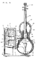
- Fig.1 is a front view partly in section of a first embodiment of a player apparatus of the present invention.
- Fig.2 is a section taken on A-A line of Fig.1.
- Fig.3 is a perspective view of a main portion constructing a first embodiment of a player apparatus of the present invention.
- Fig.4 is a circuit diagram showing an electrical structure of a first embodiment of a player apparatus of the present invention.
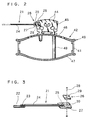
- Fig.5 is a plan view showing a main portion constructing a second embodiment of a player apparatus of the present invention.
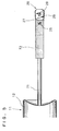
- Fig.6 is a front view partly in section of a third embodiment of a player apparatus of the present invention.
- Hereinafter will be described embodiments of the present invention with reference to the attached drawings.
- Fig.1 through Fig .4 show a first embodiment of the present invention, of which Figs.1 to 3 show a general structure of the apparatus.
Reference numeral 1 designates a pedestal, 2 a casing provided at one side thereof, all of which are constructed by assembling wooden plates. Inside thecasing 2 is provided amagnet circuit 7 comprising abottom plate 4 having acenter pole 3, anupper plate 5 and anannular magnet 6 provided therebetween, saidmagnet circuit 7 being supported by ametallic frame 8.Reference numeral 9 designates a voice coil which is able to vibrate within amagnetic gap 10 of themagent circuit 7. When a speech current flows through acoil 9A of thevoice coil 9 placed in a magentic field of themagentic circuit 7, theconductor coil 9A is displaced due to an electromagnetic induction, thus vibrating thevoice coil 9 as a whole. Namely, theaforesaid voice coil 9 and themagnetic circuit 7 construct adriving coil 11 for converting a speech current into a mechanical vibration. Onto the distal end of thevoice coil 9 is mounted acylindrical cap 12 as an vibrating part of thedriving coil 11, thus propagating the vibration outwards. In this embodiment, the diameter of thecap 12 is set at 53 mm. -
Reference numeral 13 designates a damper which serves to support thevoice coil 9 coaxially around thecenter pole 3, and thus to control unnecessary radial vibration of thevoice coil 9. For thedriving coil 11 of this embodiment, an existing cone-type speaker is used with the vibrating plate thereof being removed therefrom, while aforesaidannular magnet 6 is made of ferite-based magnet material. -
Reference numeral 21 is a rod-like member or a rod extending from the center of thecap 12 toward the outside of thecasing 2. Therod 21 comprises afirst rod member 22 having its proximal end attached to the center of thecap 12, asecond rod member 24 which is connected to the distal end of thefirst rod member 22 by ascrew 23 and aninterposing body 26 connected to the distal end of therod member 24 by anotherscrew 25. The interposingbody 26 comprises afirst fixing member 27 which is tabular and attached to thesecond rod member 24 by thescrew 25, and asecond fixing member 29 which is removably mounted to thefirst fixing memeber 27 by ascrew 28. To the respective opposite surfaces between the first andsecond fixing members non-slip members 30 such as a papersand, which can ensure the contact of the interposingmember 26 with a hereinbelow-describedbridge 45. Thus, the mechanical vibration from therod 21 can be precisely propagated to thebridge 45. - On the other hand,
reference numeral 40 designates a resilient piece which is U-shaped to supportribs 41 of a stringed instrument included in violin group. In this embodiment, aviolin 42 is fitted into theresilient piece 40 with thescroll 43 thereof being positioned upside. It should be noted that there is no difference in structure between theviolin 42 used in this embodiment and one generally available, where, as is widely recognized, a plurality ofstrings 44 are supported by thewooden bridge 45, while thebody 49 as a resonating mechanism is provided with a table 46 or so-called a belly having thebridge 45 mounted thereon, a rear table 47 spaced relative to the table 46 and asound post 48 for propagating the vibration from thebridge 45 to the rear table 47. - The aforesaid
resilient piece 40 is fixed to a movable table 51 which is slidable on thepedestal 1, while thecasing 2 is able to be raised or lowered by revolving avolt 52. Accordingly, even with the use of other violins having slightly different configurations, the movable table 51 and thevolt 52 can be adjusted so as to ensure the connecting of thebridge 45 with the distal end of therod 21. - The
first rod member 22 of this embodiment is formed to a 7mm diameter, while thesecond rod member 24 thereof a 5mm diameter. For high-fidelity reproduction of sounds out of thebody 49 of theviolin 42, it is desirable that the distance from the proximal end of thefirst rod member 22 to the point of contact between theinterposing body 26 and thebridge 45 be set at 145 mm. This should apply to the case that theviolin 42 is used as one of the stringed instruments included in violin group. - Next, the electrical structure of this embodiment will be explained with reference to Fig.4.
Reference numerals amplifier 53 or the source of speech respectively, while 54 a pair of switches for supplying a speech current from each of theoutput terminals speakers casing 2.Reference numeral 57 designates a dummy resistance having the same value of resistance of 8 ohm as that of the stereo-speaker switch 54 is shifted to a normally closedterminal 54a side (hereinafter a first side), theoutput terminal 53a is connected to thecasing 2 while theoutput terminal 53b to thedummy resistance 57. On the other hand, when theswitch 54 is shifted to a normallyopen terminal 54b side (hereinafter a second side), theoutput terminals speakers - The
casing 2 contains thereinside amain switch 61, acoil 62a of arelay 62 and aneon lamp 63 as a display, which are connected to both terminals of apower supply plug 64. When themain switch 61 is turned on, a point ofcontact 62b of therelay 62 for supplying a speech current from theoutput terminal 53a to thedriving coil 11 is allowed to connect to between anexternal terminal 65 connected to the normally closedterminal 54a of saidswitch 54 and thedriving coil 11. With the structure thus made, when themain switch 61 is turned on with theswitch 54 being shifted to aforesaid first side, the speech current from the R-channel of the stereo-amplifier 53 is supplied to the drivingcoil 11 inside thecasing 2. Alternatively, unlike this embodiment, the speech current from the L-channel of the stereo-amplifier 53 may be supplied to the drivingcoil 11. Otherwise, the combined speech current from both the channels R and L may be supplied to the drivingcoil 11. - Next, the action of the above-described structure will be explained.
- With the
second rod member 24 being fixed to thefirst rod member 22 in advance, theribs 41 of theviolin 42 are supported by theresilient piece 40, then the movable table 51 and thevolt 52 are suitably adjusted for proper positioning so that the distal end of thesecond rod member 24 may be located in the neighborhood of thebridge 45 of theviolin 42. After that, the first fixingmember 27 is attached to the distal end of thesecond rod member 24, thus sandwiching one side of thebridge 45 between the first fixingmember 27 and the second fixingmember 29. - With the
switch 54 being shifted to aforesaid second side, the speech current from the stereo-amplifier 53 is supplied across theswitch 54 to the stereo-speakers - On the other hand, when the
power supply plug 64 is inserted into a plug socket and themain switch 61 is operatively pressed with theswitch 54 being shifted to said first side, the point ofcontact 62b of therelay 62 is switched so that the speech current from the R-channel of the stereo-amplifier 53 is supplied to the drivingcoil 11. When the drivingcoil 11 converts the speech current into the mechanical vibration, it is propagated from therod 21 to thebridge 45 of theviolin 42, thus vibrating thebody 49 of theviolin 42 so as to reproduce sounds therefrom. - This embodiment of the invention is featured by making use of the resonance mechanism of stringed instruments such as a violin, a viola, a cello, a contrabass and the like included in so-called violin group, instead of the vibration plate of the conventional speaker.
- In these stringed instruments, the
strings 44 are generally allowed to vibrate by rubbing the same against a bow made of horse-hair (now shown) coated with pine resin, then the vibration thus generated is propagated from thebridge 45 to the table 46, which is further propagated across thesound post 48 to the rear table 47 having a slightly different lower natural frequency (or fundamental frequecy) than the table 46. Thus, a musical sound unique to a stringed instrument such as theviolin 42 is allowed to mainly come out of a pair of so-called f holes formed in thetale 46. At that time, the bridge plays a very important role that the side-vibration from thestrings 44 is oriented to the direction defined at the right angles thereto. - The inventor of the present invention has found out that if a mechanical vibration having a frequency equivalent to that developed by rubbing the
strings 44 against a bow is given from external to thebridge 45, there can be reproduced a musical sound which is so close to a sound from the stringed instrument as actually played that one feels that the sound thus generated is beyond comparison with the conventional highest-grade speaker. - More specifically, with such simple structure constructed by the driving
coil 11 for converting the speech current into the mecanical vibration, therod 21 having its proximal end connected to thecap 12 of the drivingcoil 11 and theviolin 42 having itsbridge 45 connected to the distal end of therod 21, the mechanical vibration from the drivingcoil 11 can be propagated from therod 21 to thebridge 45 which supports thestrings 44 of theviolin 42, whereby a musical sound can be reproduced with a highest-fidelity out of thebody 49 of theviolin 42 as if theviloin 42 were actually played. In other words, with the simple structure in which the drivingcoil 11 is connected to thebridge 45 by therod 21, you can feel as if you were listening to a live musical performance. In addition, from another aspect of the invention, the present invention is advantageous because of the following requirement. That is: it is generally said that once a stringed instrument such as a violin is overhauled or newly facbricated, its resonatingbody 49 becomes or remains difficult to vibrate, so that any excellent sounds unique to the instrument cannot be obtained unless the instrument is continuously used for one or two months. According to the invention, however, the speech current is intentionally applied to the drivingcoil 11, thus enabling the instrument to display the full ability to generate the sounds as originally expected in a short period. Namely, a player apparatus of the invention is very advantageous in that it can be used as an aging apparatus of theviolin 42 in addition to the aforesaid use as a player. - Whereas, the sound developed by musical instruments such as the
violin 42 generally has a specific range of its fundamental frequency and other frequencies which are each an integrity times as high as the fundamental frequency. Therefore, it is desirable that the frequency components of the speech current should be as close to those of the sounds developed by theviolin 42 as possible. Specifically, when a musical performance by a violin without accompaniment recorded in a cassette or a compact disc is supplied to the drivingcoil 11 as a speech current, the resonatingbody 49 of theviolin 42 does generate real sounds. This is because that the frequency components of the recorded musical performance of the violin are approximately equal to those unique to theviolin 42. - Additionally, the player apparatus of the invention can make use of other instruments included in violin group such as a viola, a cello, a contrabass and the like, thrum-type stringed instruments such as a guitar and a mandolin and even a cembalo, so that sounds comparatively close to the original sounds can be reproduced respectively. Further, the present inventor found that Sonata with the violin and the piano can also be reproduced as vividly as the original performance. Furthermore, it was also found that when the
violin 42 is replaced with a cello in this embodiment, the sound of the piano alone can also be reproduced well due to the difference in frequency components between the cello and the violin. - Incidentally, for high-fidelity reproduction of sounds out of the
body 49 of theviolin 42, the material of therod 21 must be carefully chosen in order to propagate the mechanical vibration from thecap 12 of thedrivig coil 11 with complete high-fidelity. In other words, the resilience, damping (internal friction), density, propagation velocity and natural frequency of therod 21 must be taken into consideration. - For example, taking the case of the
violin 42 being used as a stringed instrument for use with the invention, it is a matter of common knowledge today to a manufacturer of theviolin 42 that the table 46 made of a pine has the different fundamental frequency than that of the rear table 47 made of a maple, such that the adjustment of the table 46 at the musical scale ranging from C# to D and the rear table 47 from D to D# can assemble a violin which can generate excellent sounds. According to "Acoustic Technology of Violin" by C.M.Hutchins, which was published in the Japanese-version of "Science" in 1981, it is explicitly disclosed that the fundamental frequency of the table 46 should range from 139 to 148 Hz (orC# 3 to D3 at the musical scale), while that of the rear table 47 from 148 to 156 (or D3 toD# 3 at the musical scale). In accordance with the result, it is considered desirable that for theviolin 42, the fundamental frequency of therod 21 be out of the range from 139 to 156 Hz as defined by the above frequency ranges of the table 46 and rear table 47, even being inconsistent with either frequncies integrity times the above range. In the present embodiment, the distance from the proximal end of thefirst rod member 22 to the contact point between the interposingbody 26 and thebridge 45 is set at 145 mm, and that therod 21 is made of aluminium alloy alone, whereby there could be reproduced out of thebody 49 of theviolin 42 the sounds with the highest-fidelity. - In addition, as the
aforesaid damper 13 successfully can control the unnecessary radial vibration of thevoice coil 9 of the drivingcoil 11, it would eventualy follow that only the desirable front-to-back vibration of thevoice coil 9 can be propagated to the vibrating part orcap 12. Accordingly, the sounds can be reproduced with high-fidelity from thecap 12 through therod 21 with the use of theviolin 42. In that case, there should preferably be provided two ormore dampers 13, thus more effectively suppressing the radial vibration of thevoice coil 9. - When the
violin 42 is actually played by drawing a bow against thestrings 44, certain vibration will be given to the side direction of thebridge 45, i.e., the direction perpendicular to thestrings 44. The inventor has taken particular note of the fact, and thus structured the present embodiment such that therod 21 is connected to thecap 12 to propagate the front-to-back vibration of the thevoice coil 9 to the axial direction of therod 21, while therod 21 is connected to thebridge 45 to propagate the axial vibration of therod 21 to the side direction of thebridge 45. Thus, with thedamper 13 controlling the radial vibration of thevoice coil 9, the front-to-back vibration of thevoice coil 9 alone can be propagated to the side direction of thebridge 45, thereby reproducing the sounds as vividly as if thestrings 44 were actually rubbed against a bow. - In addition, it should be noted that the driving
coil 11 for use with the present embodiment can be obtained by removing the vibration plate from any exisiting speaker, without any needs of a particular structure. Accordingly, the fabrication of the appparatus will not be accompanied by any difficulty when it is actually designed. As the final quality of the sounds will also vary by replacing theviolin 42 with another, the present apparatus can be effectively utilized for examining the quality of sounds which you can expect from theviolin 42. Needless to say, you do not have to always use the built-in driving coil of the existing speaker for that of the invention. - Hereinafter will be described a second embodiment of the invention with reference to Fig.5, in which the same portions as those described in a first embodiment will be designated as common reference numerals and their repeated detailed descriptions will be omitted.
- This embodiment relates to an improved type of the
aforesaid rod 21 of a first embodiment. The rod-like member or therod 21 of a second embodiment is so structured that analuminium alloy rod 71 of 6mm diameter is connected to the center of thecap 12 of the drivingcoil 11, then to the distal end of therod 71 is fittingly bonded aPernambuco lumber 72, of which the distal end is then fixedly connected to theintreposing body 26 of a first embodiment by thescrew 25. Further, the distance from the proximal end of therod 71 to the contact point between the interposingbody 26 and thebridge 45 is set at 145 mm. Other structures of a second embodiment are totally the same as those of a first embodiement. - The
Pernambuco lumber 72 as referred to in the above paragraph is a natural wood produced in Brazil, which is well-known to one skilled in the art as a preferred raw material for a supporting member of a bow against which the strings of the stringed instruments are rubbed. As a part of therod 21 is constructed by a wood of the different nature to others, any undesirable resonant frequency of the natural frequency of themetallic rod 71 can be absorbed therein. Additionally, it is noted that thePernambuco lumber 72 is said to be the most suited for generating the excellent sounds in drawing a bow against strings. Accordingly, with the use of thePernambuco lumber 72 constructing a part of therod 21 for propagation of the mechanical vibration to thebridge 45, there can be reproduced from thebody 49 of theviolin 42 as beautiful and serene sounds as if the bow were drawn against the strings with thePernaumbuco lumber 72 being atached to the bow. In addition, since thePernambuco lumber 72 is usually used as a supporting member for a bow of not only theviolin 42 but other stringed instruments included in violin group, ths same effect can be expected even in the case that other instruments than theviolin 42 are used in the invention. - To summarize the advantage of this emboidment, when the
metallic rod 71 is connected to thePernambuco lumber 72 to fabricate therod 21, the undesirable resonant frequency unique to therod 71 can be effectively absorbed and thus can reproduce with high fidelity as beautiful and serene sounds as if a bow with thePernumbuco lumber 72 were drawn against strings. - Next, a third embodiment of the invention will be described with reference to Fig.6, in which the same portions as those described in a first embodiment will be designated as common reference numerals and their repeated detailed descriptions will be omitted.
- In a third embodiment, the
bottom plate 4 is allowed to extend outward relative to theannular magnet 6, while to front sides of the outer periphery of thebottom plate 4 are mounteddouble dampers annular member 81. Alternatively, like a first emboidment, there may be provided asingle damper 13. Theannular member 81 thus provided can make the aforesaidmetallic frame 8 of a first embodiment unnecessary. Further, instead of the ferite-based magnet of a first embodiment, theannular magnet 6 of this embodiment uses an alnico-based magnet material which indicates a larger magnetic flux density and thus a more excellent magnetic property. Whilst thefirst rod member 22 constructing therod 21 is made of hollow aluminium alloy, there is no need in this embodiment, unlike the foregoing first and second embodiments, to precisely prescribe either the aforesaid distance from the proximal end of thefirst rod member 22 to the contact point between the interposingmember 26 and thebridge 45, or the configuration and material of thefirst rod member 22. That results from the facts that theannular magnet 6 constructing the drivingcoil 11 has an excellent magnetic property and theplural dampers voice coil 9. Other structures in this embodiment is totally the same as those of a first embodiment. - Incidentally, the present invention should not be limited to the foregoing embodiments, but may be variously modified within a technical scope of the invention. For example, the rod-like member or
rod 21 may be suitably shaped otherwise, taking the properties of the various stringed instruments into consideration.
Claims (7)
- A player apparatus comprising:a driving coil (11) for converting a speech current into a mechanical vibration;a rod member (21) having its proximal end connected to a vibration part (12) of the driving coil (11);a stringed instrument (42) having its bridge (45) connected to a distal end of the rod member (21), said stringed instrument being included in a violin group.
- A player apparatus according to claim 1, wherein said driving coil (11) comprises:a magnet circuit (7);a voice coil (9) which vibrates due to an electromagnetic induction caused by the magnet circuit (7), said voice coil (9) being provided with a damper (13).
- A player apparatus according to claim 1, wherein said driving coil (11) comprises:a magnet circuit (7);a voice coil (9) which vibrates due to an electromagnetic induction caused by the magnet circuit (7), said voice coil (9) being provided with a plurality of dampers (13, 13A).
- A player apparatus according to claim 2, wherein said magnet circuit (7) comprises an alnico-based magnet material (6).
- A player apparatus according to claim 3, wherein said magnet circuit (7) comprises an alnico-based magnet material (6).
- A player apparatus according to claim 2, wherein said connection of the rod member (21) to the vibration part (12) allows a front-to-back vibration of said voice coil (9) to be propagated to an axial direction of the rod member (21), while said connection of the rod member (21) to the bridge (45) allows the axial vibration of the rod member (21) to be propagated to a side-direction of the bridge (45).
- A player apparatus according to claim 1, wherein said rod member (21) comprises a metallic rod (71) and a pernambuco lumber (72) connected thereto.
Applications Claiming Priority (3)
| Application Number | Priority Date | Filing Date | Title |
|---|---|---|---|
| JP29295795 | 1995-11-10 | ||
| JP29295795A JP3321792B2 (en) | 1995-11-10 | 1995-11-10 | Player equipment |
| JP292957/95 | 1995-11-10 |
Publications (2)
| Publication Number | Publication Date |
|---|---|
| EP0773530A2 true EP0773530A2 (en) | 1997-05-14 |
| EP0773530A3 EP0773530A3 (en) | 1999-10-20 |
Family
ID=17788624
Family Applications (1)
| Application Number | Title | Priority Date | Filing Date |
|---|---|---|---|
| EP96116952A Withdrawn EP0773530A3 (en) | 1995-11-10 | 1996-10-22 | Player apparatus |
Country Status (2)
| Country | Link |
|---|---|
| EP (1) | EP0773530A3 (en) |
| JP (1) | JP3321792B2 (en) |
Cited By (5)
| Publication number | Priority date | Publication date | Assignee | Title |
|---|---|---|---|---|
| FR2782830A1 (en) * | 1998-09-02 | 2000-03-03 | Pica Sound International | ELECTRO-ACOUSTIC MUSIC INSTRUMENT |
| FR2998086A1 (en) * | 2012-11-15 | 2014-05-16 | Ecole Norm Superieure Lyon | ASSEMBLY AND METHOD FOR AUTOMATICALLY PLAYING A FROST STRING MUSIC INSTRUMENT |
| CN109545169A (en) * | 2018-12-17 | 2019-03-29 | 王曦 | A kind of string music performance system |
| GR20180100220A (en) * | 2018-05-18 | 2020-01-22 | Ρηγας Χρηστου Μακροπουλος | Violin's electromagnetic sound-recording system |
| KR20200012353A (en) * | 2018-07-27 | 2020-02-05 | 김준구 | Strings aging device using linear reciprocating motion |
Families Citing this family (2)
| Publication number | Priority date | Publication date | Assignee | Title |
|---|---|---|---|---|
| BRPI0614750A2 (en) * | 2005-08-11 | 2016-11-08 | Agapitus B Lye | apparatus comprising an electric vibration generator attached to an easel cradle and method for maturing a string musical instrument having an easel |
| JP6503135B1 (en) * | 2018-12-19 | 2019-04-17 | 英男 大島 | Stringed instrument excitation device and stringed instrument excitation system |
Citations (1)
| Publication number | Priority date | Publication date | Assignee | Title |
|---|---|---|---|---|
| JPS5756279A (en) | 1980-09-19 | 1982-04-03 | Matsushita Graphic Commun Syst Inc | Magnetic fluid recorder |
Family Cites Families (5)
| Publication number | Priority date | Publication date | Assignee | Title |
|---|---|---|---|---|
| US4567805A (en) * | 1984-01-17 | 1986-02-04 | Clevinger Martin R | Compliant bridge transducer for rigid body string musical instruments |
| US4843937A (en) * | 1985-12-19 | 1989-07-04 | Murphy Robert T | Electrical sound detector for stringed instrument |
| US5142961A (en) * | 1989-11-07 | 1992-09-01 | Fred Paroutaud | Method and apparatus for stimulation of acoustic musical instruments |
| US5031501A (en) * | 1990-03-19 | 1991-07-16 | Ashworth William J | Method for attaching an audio transducer to a string musical instrument |
| DE4415816A1 (en) * | 1994-05-05 | 1995-11-09 | Rudolf Mendler | String instrument, e.g. violin, viola, initial tuning method |
-
1995
- 1995-11-10 JP JP29295795A patent/JP3321792B2/en not_active Expired - Fee Related
-
1996
- 1996-10-22 EP EP96116952A patent/EP0773530A3/en not_active Withdrawn
Patent Citations (1)
| Publication number | Priority date | Publication date | Assignee | Title |
|---|---|---|---|---|
| JPS5756279A (en) | 1980-09-19 | 1982-04-03 | Matsushita Graphic Commun Syst Inc | Magnetic fluid recorder |
Cited By (10)
| Publication number | Priority date | Publication date | Assignee | Title |
|---|---|---|---|---|
| FR2782830A1 (en) * | 1998-09-02 | 2000-03-03 | Pica Sound International | ELECTRO-ACOUSTIC MUSIC INSTRUMENT |
| WO2000014720A1 (en) * | 1998-09-02 | 2000-03-16 | Pica-Sound International | Electro-acoustic musical instrument |
| FR2998086A1 (en) * | 2012-11-15 | 2014-05-16 | Ecole Norm Superieure Lyon | ASSEMBLY AND METHOD FOR AUTOMATICALLY PLAYING A FROST STRING MUSIC INSTRUMENT |
| WO2014076144A1 (en) * | 2012-11-15 | 2014-05-22 | Ecole Normale Supérieure De Lyon (Ensl) | Assembly and method for automatically playing a strummed stringed musical instrument |
| GR20180100220A (en) * | 2018-05-18 | 2020-01-22 | Ρηγας Χρηστου Μακροπουλος | Violin's electromagnetic sound-recording system |
| GR1009745B (en) * | 2018-05-18 | 2020-05-29 | Ρηγας Χρηστου Μακροπουλος | Violin's electromagnetic sound-recording system |
| KR20200012353A (en) * | 2018-07-27 | 2020-02-05 | 김준구 | Strings aging device using linear reciprocating motion |
| KR102116611B1 (en) * | 2018-07-27 | 2020-06-05 | 김준구 | Strings aging device using linear reciprocating motion |
| CN109545169A (en) * | 2018-12-17 | 2019-03-29 | 王曦 | A kind of string music performance system |
| CN109545169B (en) * | 2018-12-17 | 2024-03-19 | 王曦 | String music playing system |
Also Published As
| Publication number | Publication date |
|---|---|
| EP0773530A3 (en) | 1999-10-20 |
| JPH09134168A (en) | 1997-05-20 |
| JP3321792B2 (en) | 2002-09-09 |
Similar Documents
| Publication | Publication Date | Title |
|---|---|---|
| US9263015B2 (en) | Wireless electric guitar | |
| US7256342B2 (en) | Sound pickup device for percussion instrument | |
| US5142961A (en) | Method and apparatus for stimulation of acoustic musical instruments | |
| US8319088B1 (en) | Poly-coil matrix | |
| Corbett | Mic it!: microphones, microphone techniques, and their impact on the final mix | |
| CN105264593A (en) | Device for vibrating a stringed instrument | |
| JP2002539479A (en) | Musical instrument | |
| WO2016111330A1 (en) | Evaluation method for audio device, device for evaluation method, audio device, and speaker device | |
| US8633370B1 (en) | Circuits to process music digitally with high fidelity | |
| EP0773530A2 (en) | Player apparatus | |
| US20020114481A1 (en) | Speaker apparatus | |
| US2087106A (en) | Electrical musical instrument | |
| CN100390858C (en) | A passive electric string instrument | |
| US3821475A (en) | Sound enhancement speaker enclosure | |
| JP2010136313A (en) | Sound source playback device by guitar and sound source recorder for the same | |
| CN105744443B (en) | Digital audio processing system for stringed musical instrument | |
| US3629483A (en) | Multivocal music system | |
| JP2000148148A (en) | Stringed instrument | |
| US9247339B2 (en) | Loudspeaker design | |
| WO2008013003A1 (en) | Automatic violin | |
| CN121545475A (en) | A sound-to-electric recording device and an electro-acoustic device based on stringed musical instruments | |
| CN205726356U (en) | Digital Audio Processing System for Stringed Instruments | |
| JP5898910B2 (en) | Harmonic speaker | |
| JP2004129058A (en) | Concert system by speaker using stringed musical instrument | |
| JP6359707B1 (en) | Sound equipment |
Legal Events
| Date | Code | Title | Description |
|---|---|---|---|
| PUAI | Public reference made under article 153(3) epc to a published international application that has entered the european phase |
Free format text: ORIGINAL CODE: 0009012 |
|
| AK | Designated contracting states |
Kind code of ref document: A2 Designated state(s): DE FR GB IT NL |
|
| PUAL | Search report despatched |
Free format text: ORIGINAL CODE: 0009013 |
|
| AK | Designated contracting states |
Kind code of ref document: A3 Designated state(s): DE FR GB IT NL |
|
| RIC1 | Information provided on ipc code assigned before grant |
Free format text: 6G 10D 3/16 A, 6G 10F 1/18 B, 6H 04R 1/42 B |
|
| 17P | Request for examination filed |
Effective date: 20000128 |
|
| 17Q | First examination report despatched |
Effective date: 20020208 |
|
| STAA | Information on the status of an ep patent application or granted ep patent |
Free format text: STATUS: THE APPLICATION IS DEEMED TO BE WITHDRAWN |
|
| 18D | Application deemed to be withdrawn |
Effective date: 20020619 |