EP0773616B1 - Sammelschienenanordnung mit Befestigungsmitteln hierfür - Google Patents
Sammelschienenanordnung mit Befestigungsmitteln hierfür Download PDFInfo
- Publication number
- EP0773616B1 EP0773616B1 EP96118193A EP96118193A EP0773616B1 EP 0773616 B1 EP0773616 B1 EP 0773616B1 EP 96118193 A EP96118193 A EP 96118193A EP 96118193 A EP96118193 A EP 96118193A EP 0773616 B1 EP0773616 B1 EP 0773616B1
- Authority
- EP
- European Patent Office
- Prior art keywords
- stud
- bus bar
- keeper
- clip
- bar
- Prior art date
- Legal status (The legal status is an assumption and is not a legal conclusion. Google has not performed a legal analysis and makes no representation as to the accuracy of the status listed.)
- Expired - Lifetime
Links
- 238000000034 method Methods 0.000 claims description 8
- 239000004020 conductor Substances 0.000 claims 1
- 238000004519 manufacturing process Methods 0.000 claims 1
- 125000006850 spacer group Chemical group 0.000 description 14
- 229910001369 Brass Inorganic materials 0.000 description 11
- 239000010951 brass Substances 0.000 description 11
- 229910000831 Steel Inorganic materials 0.000 description 4
- 239000010959 steel Substances 0.000 description 4
- 230000004075 alteration Effects 0.000 description 3
- 230000007935 neutral effect Effects 0.000 description 3
- 230000005540 biological transmission Effects 0.000 description 2
- 238000010276 construction Methods 0.000 description 2
- 238000003780 insertion Methods 0.000 description 2
- 238000012986 modification Methods 0.000 description 2
- 230000004048 modification Effects 0.000 description 2
- RYGMFSIKBFXOCR-UHFFFAOYSA-N Copper Chemical compound [Cu] RYGMFSIKBFXOCR-UHFFFAOYSA-N 0.000 description 1
- 229910000639 Spring steel Inorganic materials 0.000 description 1
- 230000000712 assembly Effects 0.000 description 1
- 238000000429 assembly Methods 0.000 description 1
- 230000004323 axial length Effects 0.000 description 1
- 238000005452 bending Methods 0.000 description 1
- 230000015572 biosynthetic process Effects 0.000 description 1
- 230000005494 condensation Effects 0.000 description 1
- 238000009833 condensation Methods 0.000 description 1
- 239000010949 copper Substances 0.000 description 1
- 229910052802 copper Inorganic materials 0.000 description 1
- 238000005260 corrosion Methods 0.000 description 1
- 230000007797 corrosion Effects 0.000 description 1
- 230000001419 dependent effect Effects 0.000 description 1
- 239000004519 grease Substances 0.000 description 1
- 238000009434 installation Methods 0.000 description 1
- 238000003825 pressing Methods 0.000 description 1
- 238000004080 punching Methods 0.000 description 1
- 238000003466 welding Methods 0.000 description 1
Images

Classifications
-
- H—ELECTRICITY
- H02—GENERATION; CONVERSION OR DISTRIBUTION OF ELECTRIC POWER
- H02B—BOARDS, SUBSTATIONS OR SWITCHING ARRANGEMENTS FOR THE SUPPLY OR DISTRIBUTION OF ELECTRIC POWER
- H02B1/00—Frameworks, boards, panels, desks, casings; Details of substations or switching arrangements
- H02B1/20—Bus-bar or other wiring layouts, e.g. in cubicles, in switchyards
-
- H—ELECTRICITY
- H01—ELECTRIC ELEMENTS
- H01R—ELECTRICALLY-CONDUCTIVE CONNECTIONS; STRUCTURAL ASSOCIATIONS OF A PLURALITY OF MUTUALLY-INSULATED ELECTRICAL CONNECTING ELEMENTS; COUPLING DEVICES; CURRENT COLLECTORS
- H01R4/00—Electrically-conductive connections between two or more conductive members in direct contact, i.e. touching one another; Means for effecting or maintaining such contact; Electrically-conductive connections having two or more spaced connecting locations for conductors and using contact members penetrating insulation
- H01R4/28—Clamped connections, spring connections
- H01R4/30—Clamped connections, spring connections utilising a screw or nut clamping member
-
- H—ELECTRICITY
- H02—GENERATION; CONVERSION OR DISTRIBUTION OF ELECTRIC POWER
- H02G—INSTALLATION OF ELECTRIC CABLES OR LINES, OR OF COMBINED OPTICAL AND ELECTRIC CABLES OR LINES
- H02G5/00—Installations of bus-bars
- H02G5/02—Open installations
- H02G5/025—Supporting structures
-
- Y—GENERAL TAGGING OF NEW TECHNOLOGICAL DEVELOPMENTS; GENERAL TAGGING OF CROSS-SECTIONAL TECHNOLOGIES SPANNING OVER SEVERAL SECTIONS OF THE IPC; TECHNICAL SUBJECTS COVERED BY FORMER USPC CROSS-REFERENCE ART COLLECTIONS [XRACs] AND DIGESTS
- Y10—TECHNICAL SUBJECTS COVERED BY FORMER USPC
- Y10T—TECHNICAL SUBJECTS COVERED BY FORMER US CLASSIFICATION
- Y10T403/00—Joints and connections
- Y10T403/71—Rod side to plate or side
-
- Y—GENERAL TAGGING OF NEW TECHNOLOGICAL DEVELOPMENTS; GENERAL TAGGING OF CROSS-SECTIONAL TECHNOLOGIES SPANNING OVER SEVERAL SECTIONS OF THE IPC; TECHNICAL SUBJECTS COVERED BY FORMER USPC CROSS-REFERENCE ART COLLECTIONS [XRACs] AND DIGESTS
- Y10—TECHNICAL SUBJECTS COVERED BY FORMER USPC
- Y10T—TECHNICAL SUBJECTS COVERED BY FORMER US CLASSIFICATION
- Y10T403/00—Joints and connections
- Y10T403/75—Joints and connections having a joining piece extending through aligned openings in plural members
Definitions
- This invention relates generally as indicated to a bus bar assembly, fastening system therefor, and method, and more particularly to an electrical panel construction as known, for example from US-A-5,364,203.
- High current relatively low voltage power transmission from transformers or generators to using apparatus such as welders or motors frequently employs bus bars which usually extend through enclosures and through enclosed panels where branches or connections are made.
- Most such power transmission is a three phase system or a three phase and neutral system.
- Each phase and the neutral are laterally spaced.
- the spacing between phases and the neutral may be from about 50 to about 90mm. If each phase is a multi-bar system or more than a single bar, such as three bars, then the phase spacing is usually measured from the center bar thus reducing the open spacing between phases. In a multi-bar phase, the spacing between bars within a phase is much less.
- the lateral spacing between bars in a given phase may run from about 4 to about 15mm, depending on a number of factors such as bar size. A typical lateral spacing dimension within a phase would be on the order of 5mm.
- a headed bolt cannot be inserted in the space between bars of the same phase because of the close spacing (5mm e.g.), it has to be inserted through all three bars of a three bar phase. If the connection is made between two of the three bars, a spacer is required between the two bars and the third. Two spacers may be required if the connection is made to the outside of an outside bar since the fastener has to go through all three bars. At the least, the fastening system requires a bolt, nut, four washers and one or two spacers, as well as two wrenches, one of which may be a torque wrench.
- US-A-5 364 203 is another bus bar connecting device known, which comprises a clamper for clamping two bus bars, wherein the first bus bar has a hole, a bolt extends through the clamper and the hole, and the bolt is screwed into a nut provided on the opposite side of the bus bar. Thereby the clamper is pressed against the other bus bar, pressing the second bus bar against the first bus bar.
- the nut can be embodied as a large sized, special, pressure-insertion type nut which is pressure-inserted into the hole, which has a larger diameter than the hole which was described in the other embodiment.
- the bus bar assembly and fastening system comprises a headless stud threaded on one end for application of the contact washer, flat washer and nut found in conventional systems.
- the opposite end of the stud is provided with diametrically opposed symmetrical flats, spaced slightly from such opposite end, each of which flats provides a stop shoulder at both ends.
- the length of the stud from the threaded end section to the flats varies depending on the application. The length may be such to extend appropriately through a single bar, two bars, three bars, or all four bars, of one phase, and whatever is clamped or connected thereto.
- a clip which includes a keeper slips over the edge of a bar and includes a yoke or open slot interfitting with such flats, both to keep the stud from moving axially and also from rotating about its axis. Rotation of the keeper is prevented by a short gauge flange which seats against the edge of the bar or other object clamped.
- the open slot or yoke extends normal to the gauge flange.
- the slot of the keeper has pilot surfaces to make it easy to assemble the keeper and stud.
- a spring clip is assembled with the keeper and engages the opposite end of the stud just beyond the flats to keep the keeper in place once assembled on the stud simply by pushing the keeper over the stud flats with finger pressure.
- the spring clip includes two spaced short parallel pressure flanges which embrace the stud. The keeper and clip are thus held in place with the gauge flange against the gauging edge of the bar or other object.
- the present invention allows the fixation between the bars or to bars without spacers between the bars, and more importantly, without a headed bolt, with washers being required to be inserted through bars and spacers from the rear, and out of sight, or requiring a nut and washer assembly to be threaded on by feel and then wrench tightened.
- the present invention may be assembled and tightened with only one wrench and even where there is no access on one side.
- the keeper provides the correct contact pressure even with reduced transverse dimensions as opposed to the diameter of a contact washer.
- the keeper also resists bending of the bar or bar clamp, or lug, for example, which may be used in conjunction with the bar. It also suppresses heat rise and the resulting problems.
- the system may be used with or without the stud passing through bar holes and facilitates the attachments of cables or jumpers, for example, with crimped lugs to the bars. With a special grooved clamp washer, wires or small cables may quickly be attached to the bar or other conductive surface. Importantly, the system significantly reduces the number of parts and minimizes the dropping or losing of parts. At the same time, the system enables quick and easy connection without spacers in locations which could not be utilized before since conventional fasteners would not fit, and it was simply too much trouble to disassemble the cabinet or panel system to make the connection.
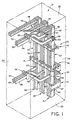
- FIG. 1 there is illustrated a portion of a bus bar panel system shown generally at 20 which is normally situated within a cabinet or enclosure 21.
- the cabinet includes a top 22, a bottom 23, a backwall 24 and a front 25, the latter usually being provided with doors providing access to the panel system.
- the cabinet normally includes a frame and the doors are normally smaller than the front of the cabinet. Access to such cabinet is normally only through the front doors unless the top or back is disassembled.
- the bus bar panel system illustrated is a typical three phase system with the three phases being shown at 28, 29 and 30.
- each phase is a multi-bar phase and in the illustration, the three phases enter from the right hand side of Figure 1 near the bottom in four bar phases seen at 32, 33 and 34, respectively.
- Such horizontal runs at the bottom of the panel are connected to vertical runs of three bars each seen at 35, 36 and 37, respectively.
- the bus bars of each phase are held in place by bus bar supports seen at 40 and 41 which support, grip, and maintain the spacing of the bars, both between phases and within a given phase. From the top of the vertical runs, the phases continue with two bar runs shown at 43, 44 and 45.
- bus bar panel system are constructed preferably with perforated bus bar of the type sold by ERICO FRANCE, under the registered trademark ERIFLEX®.
- bus bar has perforations or holes spaced relatively close to the edge on generally uniform centers as seen at 47. Such holes facilitate the fastening and clamping of the various connections and make use of the fastening system of the present invention somewhat easier.
- the horizontal and vertical runs of the multi-bar phases illustrated in Figure 1 are interconnected by fasteners shown generally at 48 and 49 in accordance with the present invention.
- Figure 1 also illustrates the connection of three flexible bus bars 52, 53 and 54 which extend through spacers 55, and which are connected to the respective phases at 56, 57 and 58, respectively.
- the bus bars may be of the insulated flexible type such as sold by ERICO FRANCE, under the registered trademark FLEXIBAR®.
- Such flexible insulated bus bars are illustrated, for example, in Applicants French Patent No. 81 23417.
- Each of the respective flexible bus bars is connected to the face of the bar in the three bar phase set facing the viewer.
- Each of the connections utilizes a brass clamp 60 and the fastening system of the present invention.
- three flexible bus bars indicated at 63, 64 and 65 extend through spacers 66 and are connected at 67, 68 and 69 to the three bar vertical runs of each phase.
- Each flexible bus bar is connected between two of the three bars in each phase utilizing the fastening system of the present invention.
- the flexible bus bars extend to connections for utilizing apparatus and the bus bar panel in its entirety is usually more crowded and complex than Figure 1 would indicate.
- the spacing between the phases may vary from approximately 50 to 90mm and be even less with multi-bar phases.
- the spacing between the bars in a given phase may typically be only 5mm or somewhat more, and connections such as shown at 56-58 or 67-69 would normally require a fastener inserted through all bars of the phase with spacers between the side-by-side bars within a given phase.
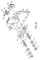
- the fastening system includes a stud 72 which has a threaded section 73 on one end and parallel diametrically opposed flats 74 and 75 on the other end. The flats are quite close to the other or projecting end indicated at 76.
- the system includes a conventional flat washer 77, a dished contact washer 78, and a nut 79 having internal threads 80 matching the threads 73.
- a two part keeper clip shown generally at 82 which includes a keeper 83 and a spring clip 84 which parts are connected to each other.
- the keeper includes a relatively short gauge flange 86 and a major body portion 87 extending at a right angle to the gauge flange 86.
- the interior of the gauge flange seen at 88 is designed to engage the edge of the bus bar with the body 87 extending parallel to the face of the bus bar.
- the edge 90 of the body farthest from the gauge flange includes an open slot 91, the interior of which at the edge 90 includes tapered pilot surfaces 92 and 93. These are seen more clearly in Figure 5.
- the spring clip 84 includes a relatively short flange 95 and a body 96 which includes a cut-out 97 forming two legs 98 and 99.
- the inner edges of the two legs are bent outwardly to form spring lips 100 and 101, respectively, which as indicated in Figures 3 and 4, are spaced wider than the slot 91 in the keeper body, but slightly more narrow than the diameter of the stud.
- the spring portion of the clip may be made of relatively thin spring steel while the thicker keeper may be made of simple sheet steel.
- the spring clip and the keeper may be joined in a variety of ways.
- rivet studs 103 and 104 which may be formed in the keeper body by punching from the opposite side.
- the rivet studs may extend through holes 105 and 106 in the legs of the spring clip and are flattened as indicated at 107.
- the spring clip and keeper may be joined in a variety of other ways, such as by tack welding. When the parts are joined, it is important that the lips of the spring clip be parallel and centered with respect to the slot 91.
- the flats 74 and 75 each form two stop shoulders seen at 108 and 109.
- the stud is inserted through a hole in the bus bar until the end 76 projects slightly from the bus bar.
- the keeper clip is then inserted behind the bus bar and pushed down until the gauge flange interior 88 contacts the edge of the bus bar seen at 110 in Figure 4.
- the open slot 91 straddles the stud flats as indicated in Figure 3 and is pushed to its seated position when the underside of the gauge flange 88 contacts the edge of the bus bar 110.
- the spring lips 100 and 101 embrace the relatively-short portion 111 of the stud extending beyond the shoulder 109 in Figure 2 gripping or grasping the stud. This enables the installer to release the clip without fear of it dropping or falling off leaving both hands free to form the connection and install the washers 77 and 78 as well as the nut 79.
- the clip has to extend beyond the distance D which is the distance from the interior of the gauge flange to the stud. It is also the distance from the outer edge of the holes or perforations in the bus bar to the edge of the bus bar. The body of the clip has to exceed such distance in order to interengage with the stud.
- the keeper body extends considerably beyond such distance straddling the flats and that the area of the keeper body in pressure contact with the face of the bus bar is substantially greater than the area of the nut and washer system, and yet the width of the keeper body measured lengthwise of the bus bar is less than the diameter of the washer 77.
- connection like that shown at 58 in Figure 1.
- the connection joins insulated bus bar 54 to the perforated bus bar 114 which has the perforations 115 therein on uniform centers along each edge, again each perforation being spaced the distance D from the edge as seen in Figure 4.
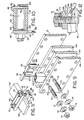
- the brass clamp shown at 60 is simply a rigid brass channel having ends 116, two upturned edge flanges 117 and 118, and holes 120 and 121 in each end which are spaced from the ends 116 of the channel the same distance D as the holes 122 and 123 in the bus bar 114 are spaced from the edges.
- FIG 9 there is illustrated the three bars of one phase seen at 128, 129 and 130, while the first bar of the next phase is seen at 131.
- the spacing between the bars of a common phase is quite close and as indicated may be on the order of approximately 5mm.
- the spacing to the next phase is substantially larger.
- the bare portion 132 of the flexible bus 133 is inserted between the bars 128 and 129.
- the studs 72 are inserted through the appropriate holes in the bus bar on each side of the bare end of the insulated bus bar and the keeper clip assemblies are inserted between bars 129 and 130 to engage the flats of the studs.
- the washers and nuts are then assembled to clamp the insulated bus between the bars 128 and 129 of a common phase. No spacer is required between the bars 129 and 130 as would normally be required with a conventional fastening system.
- Figure 10 illustrates the fastening system of the present invention in a somewhat different application.
- Figure 10 illustrates two parallel bus bars 140 and 141 with the swaged lug 142 of cable 143 attached to the ends or edges of the bar seen at 143 and 144.
- the lug bridges the edges of the bars and includes a hole accommodating the stud 72.
- the keeper clip simply takes the place of an enlarged stud head and two washers on the opposite end, but the headless stud 72 enables the stud to be inserted from the left rather than the right as seen in Figure 10.
- the clip may be installed simply by bringing the gauge flange into engagement with the face of the bar 140 at the edge. Again, the spring lips 100 and 101 maintain the keeper in place to enable the installer to use both hands to assemble the lug, washers and nut on the threaded projecting end of the stud.
- FIG 11 there is illustrated a splice between what may be a rigid bus bar 150 and the bare end 151 of insulated bus bar 152.
- Two brass clamps 60 are employed on opposite sides of the lap splice and two studs and two keeper clips. As illustrated, the headless studs are inserted from the top as seen in Figure 11 and the keeper clips are installed by sliding the clips between the channel flanges until the gauge flange 86 engages the end 116 of the brass clamp.
- the hole in the brass clamp is preferably spaced from the end again the distance D so that the keeper clip can easily be inserted by sliding it over the end of the brass clamp until the spring portion of the clip grasps the end of the stud when the gauge flange is in engagement with the end 116 of the brass clamp. Uniform tightening of the nuts will provide good electrical contact between the bus bars.
- the fastening system of the present invention is employed to attach the bare end 153 of a cable 154 to the face 155 of bus bar 156.
- a disc 157 is provided which has a half round radial or chordal groove 158 in its interior face. With the bare end 153 of the cable or wire 154 inserted in the groove, the tightening of the nut 79 will firmly press the bare end against the face 155 of the bus bar 156.
- the keeper 82 is employed behind the bus bar or on the opposite face.
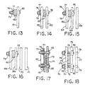
- FIGs 13, 14, 15 and 16 there is illustrated a flexible bus 160 fastened to a single bar 161 in Figure 13, between two bars 162 and 163 in Figure 14, and between two of three bars 164, 165 and 166 in Figure 15.
- the flexible bus is inserted between two bars of a four bar phase seen at 168, 169, 170 and 171.
- a headed fastener would normally have to be inserted from the right hand side of all of the bars in the phase because there simply is not space between the bars in the phase to insert a headed fastener.
- the fastener would have to be of substantial length and may even be too long even to fit between two phases which would then require partial disassembly of either a phase or the enclosure for the panel.
- all of the bars would have to be drilled and spacers would be required between bars 165 and 166 in Figure 15 and also between bars 169, 170 and 171 in Figure 16 to achieve the proper clamping pressure.
- a brass clamp 60 clamping a flexible bus 173 to the face of bus bar 174.
- the brass clamp 60 bridges the flexible bus and clamps it to the face of the bus bar.
- the keeper 82 may be utilized either with the bus bar 174 gauging on the edge, or with the brass clamp gauging on the end 116.
- Figure 18 illustrates a flexible bus 173 clamped between two bars 175 and 176 of a three bar phase which includes bar 177. It can be appreciated that if the bars are perforated as indicated at 178 and 179, it makes the use and installation of the fastener system much more expedient since otherwise holes would have to be drilled both in the bar and in spacers, and the surfaces prepared for the fastening system to achieve the desired electrical connection.
- the dimensions of the fastening system may vary, and particularly the length of the stud.
- the length of the stud may vary from approximately 35 to approximately 70mm.
- the length of the threaded section may vary from approximately 26 to about 61mm while the axial length of the flats may be on the order of from about 3mm to about 5mm, while the thickness of the keeper body is about 2mm.
- the overall thickness of the body including the spring lips is on the order of 4mm which enables it readily to slip between bus bars which are spaced only 5mm apart.
- a bus bar which has a hole spaced from the edge a distance D and the fastening system which includes a stud adapted to extend through the hole, and a keeper interfitting with the stud.
- the keeper has a short gauge flange adapted to engage the edge of the bar and a body projecting normal to the gauge flange which extends greater than the distance D from the interior of the gauge flange to interfit with the stud.
- the fastening system includes a headless stud having threads on one end and flats on the other whereby the flatted end may be inserted through the hole in the bus bar with the threaded end projecting toward the installer.
- the clip is then adapted to be slipped behind the bus bar to engage the flats and grip the stud so that the installer may then have both hands free to make the connection.
- the present invention avoids the losing and dropping of parts within the cabinet, substantially reduces the number of parts needed to make such connections, and actually improves the quality of the electrical connection by distributing the clamping force of the connection over a larger area of the face of the bar. There is, however, insufficient steel in the fastening system to create heat problems.
Landscapes
- Engineering & Computer Science (AREA)
- Power Engineering (AREA)
- Connections By Means Of Piercing Elements, Nuts, Or Screws (AREA)
- Connections Arranged To Contact A Plurality Of Conductors (AREA)
- Multi-Conductor Connections (AREA)
- Slide Fasteners (AREA)
- Installation Of Bus-Bars (AREA)
Claims (23)
- Anordnung zur Befestigung einer Sammelschiene (37, 114, 54) und dergleichen, wobei die Sammelschienen ein Loch (47, 122, 123) aufweisen, welches von der Kante (110) der Sammelschiene mit einem Abstand (D) beabstandet ist, mit einem Befestigungssystem für solche Sammelschienen, das eine Stiftschraube (72), die dafür eingerichtet ist, sich durch das Loch (47, 122, 123) zu erstrecken, und einen Schließhaken (82), der dafür eingerichtet ist, mit der Stiftschraube (72) ineinanderzupassen, umfaßt,
dadurch gekennzeichnet, daß
der Schließhaken (82) umfaßteinen kurzen Paßflansch (6), der dafür eingerichtet ist, in die Kante der Sammelschiene (110) einzugreifen, undeinen Schließhakenkörper (83), der senkrecht zu dem Paßflansch (86) vorspringt, und der sich länger als der Abstand (D) von dem Inneren des Paßflansches (86) erstreckt, um mit der Stiftschraube (72) ineinanderzupassen. - Anordnung gemäß Anspruch 1, welche Vorrichtungen aufweist, die den Schließhaken (82) und die Stiftschraube (72) operativ zusammenhalten, wenn sie richtig ineinandergreifen.
- Anordnung gemäß Anspruch 1 oder 2, welche eine Flachstelle (74, 75) an der Stiftschraube (72) aufweist, die einen Anschlag bildet, der dafür eingerichtet ist, in den Schließhakenkörper (83) einzugreifen.
- Anordnung gemäß irgendeinem der vorherigen Ansprüche, wobei der Schließhakenkörper (83) eine feste Platte ist, die sich jenseits und auf beiden Seiten der Stiftschraube (73) parallel zu der Fläche der Sammelschiene (37, 114, 54) erstreckt, um Zugkräfte auf der Stiftschraube über einen großen Bereich der Fläche der Schiene zu verteilen.
- Anordnung gemäß irgendeinem der vorherigen Ansprüche, wobei die Sammelschiene mit Kantendurchbohrungen versehen ist, welche eine Vielzahl von Löchern (48, 122, 123) entlang der Kante (110) und davon beabstandet angeordnet bilden.
- Anordnung gemäß irgendeinem der vorherigen Ansprüche, wobei diametral gegenüberliegende Flachstellen (74, 75) auf der Stiftschraube vorgesehen sind, wobei der Schließhakenkörper (83) die Stiftschraube überspannt und mit beiden Flachstellen ineinandergreift.
- Anordnung gemäß irgendeinem der vorherigen Ansprüche, wobei der Schließhakenkörper (83) einen offenen Schlitz (91) umfaßt, und die Stiftschraube Flachstellen (74, 75) umfaßt, die mit den Schlitzkanten ineinandergreifen.
- Anordnung gemäß irgendeinem der vorherigen Ansprüche, wobei der Schließhaken (82) eine Federklemme (84) aufweist, welche daran befestigt ist, um den Schließhaken (82) operativ an der Stiftschraube (73) zu halten, wenn der Schließhaken und die Stiftschraube ineinandergreifen.
- Anordnung gemäß Anspruch 8, wobei die Abmessung des Schließhakenkörpers (83) axial zu der Stiftschraube ungefähr 2 mm und zusammen mit der Federklemme (84) weniger als 5 mm beträgt.
- Anordnung gemäß irgendeinem der vorherigen Ansprüche, wobei die Stiftschraube (72) ein gewindetes Ende (73) und einen Anschlag (108, 109) an dem gegenüberliegenden Ende (76) aufweist, und wobei der Schließhaken (82) eine Klemme (84) ist, die dafür eingerichtet ist, mit dem Anschlag (108, 109) ineinanderzugreifen, wobei eine Mutter- und Unterlegscheibenanordnung (77, 78, 79), die auf dem gewindeten Ende (73) festgezogen ist, eine Klemmverbindung mit der Sammelschiene (37,114) bilden kann.
- Anordnung gemäß Anspruch 10, wobei der Paßflansch (86) in die Kante der Sammelschiene (110) für eine richtige Positionierung der Klemme (84) eingreift, um mit dem Anschlag (108, 109) ineinanderzugreifen.
- Anordnung gemäß Anspruch 10 oder 11, wobei die Stiftschraube (78) diametral gegenüberliegende Flachstellen (74, 75) umfaßt, welche symmetrische Anschläge (108, 109) bilden, und wobei die Klemme eine feste Schließhakenplatte umfaßt, welche einen offen Schlitz aufweist, der die Flachstellen überspannt und richtig in sie eingreift, wie von dem Paßflansch (86) bestimmt.
- Anordnung gemäß irgendeinem der Ansprüche 10 bis 12, wobei die Klemme (84) einen Federbereich (97, 98, 99) aufweist, der dafür eingerichtet ist, die Stiftschraube einzufassen, um den Schließhaken (82) in Position zu halten, wenn die Klemme richtig mit der Stiftschraube ineinandergreift.
- Anordnung gemäß irgendeinem der Ansprüche 10 bis 13, wobei der Federbereich (97, 98, 99) gegenüberliegende Federlippen (100, 101) aufweist.
- Anordnung gemäß Anspruch 10, welche eine feste Klemmstange (60) mit Löchern (120, 121) an jedem Ende (116) aufweist, um die Stiftschrauben (73) aufzunehmen, um die Befestigung an der Sammelschiene zu erleichtern.
- Anordnung gemäß Anspruch 10, welche eine Scheibe (157) mit einer halbkreisförmigen Rille (158) in einer Fläche aufweist, die dafür eingerichtet ist, einen Leiter (153, 154) an der Fläche (155) einer Sammelschiene zu befestigen, wenn die Scheibe an der Fläche einer Sammelschiene befestigt ist
- Verfahren zur Herstellung elektrischer Anschlüsse an einer Sammelschiene (37, 114, 54) und dergleichen, mit den chronologischen Schritten:a) Ausbildung eines Querloches (47, 122, 123) in der Sammelschiene mit einem Abstand (D) von deren Kante (110)b) Einführen der gewindeten Stiftschraube (72) von der Vorderfläche der Sammelschiene durch das Loch, um leicht von der Rückseite der Sammelschiene aus vorzuspringenc) Anbringung einer Klemme (84) auf der Rückseite der Sammelschiene, um mit der Stiftschraube ineinanderzugreifen, um zu verhindern, daß sich die Stiftschraube dreht undd) Herstellung einer Klemmverbindung (77, 78, 79) an der Vorderfläche oder der gegenüberliegenden Fläche der Schiene unter Verwendung der gewindeten Stiftschraube.
- Verfahren gemäß Anspruch 17, welches den Schritt beinhaltet, bei welchem die Kante (110) der Schiene verwendet wird, um die korrekte Position der Klemme (84) auf der Fläche der Schiene für den Eingriff der Stiftschraube (73) festzulegen.
- Verfahren gemäß Anspruch 17 oder 18, welches den Schritt beinhaltet, bei welchem die Stiftschraube (73) mit der Klemme (84) ineinandergreift, wenn die letztere sich in der korrekten Position im Eingriff mit der Stiftschraube befindet.
- Verfahren gemäß irgendeinem der Ansprüche 17 bis 19, welches den Schritt beinhaltet, bei welchem die Klemme (84) mit einem Paßflansch (86) versehen wird, um operativ mit der Kante (110) der Schiene einzugreifen, und mit einem festen Körperbereich (97), der sich von dem Inneren des Paßflansches über eine größere Strecke als der Abstand (D) zwischen den Löchern (47, 122, 123) und der Kante (110) erstreckt, um mit der Stiftschraube ineinanderzugreifen.
- Verfahren gemäß irgendeinem der Ansprüche 17 bis 20, welches den Schritt beinhaltet, bei welchem die Stiftschraube mit diametral gegenüberliegenden Flachstellen (74, 75) versehen wird, und bei welchem der feste Körperbereich mit einem offenen Schlitz versehen wird, um die Flachstellen zu überspannen und mit ihnen ineinanderzugreifen, wenn er richtig positioniert ist.
- Verfahren gemäß irgendeinem der Ansprüche 17 bis 21, welches den Schritt beinhaltet, bei welchem der feste Körper mit einer großen Fläche versehen wird, um eine Druckkonzentration um das Loch herum zu vermeiden, wenn die Verbindung festgezogen wird, und mit einem Federbereich (97, 98, 99), welcher die Stiftschraube einfaßt, wenn er richtig positioniert ist
- Verfahren gemäß irgendeinem der Ansprüche 17 bis 22, welches den Schritt beinhaltet, bei welchem Federlippen (100,101) angeordnet werden, um das Stiftschraubenende einzufassen, wenn der feste Körper mit den Flachstellen (74,75) ineinandergreift.
Applications Claiming Priority (2)
| Application Number | Priority Date | Filing Date | Title |
|---|---|---|---|
| US556582 | 1990-07-20 | ||
| US08/556,582 US5749671A (en) | 1995-11-13 | 1995-11-13 | Bus bar assembly, fastening system therefor, and method |
Publications (2)
| Publication Number | Publication Date |
|---|---|
| EP0773616A1 EP0773616A1 (de) | 1997-05-14 |
| EP0773616B1 true EP0773616B1 (de) | 2002-03-27 |
Family
ID=24221951
Family Applications (1)
| Application Number | Title | Priority Date | Filing Date |
|---|---|---|---|
| EP96118193A Expired - Lifetime EP0773616B1 (de) | 1995-11-13 | 1996-11-13 | Sammelschienenanordnung mit Befestigungsmitteln hierfür |
Country Status (4)
| Country | Link |
|---|---|
| US (2) | US5749671A (de) |
| EP (1) | EP0773616B1 (de) |
| AT (1) | ATE215276T1 (de) |
| DE (1) | DE69620101T2 (de) |
Cited By (1)
| Publication number | Priority date | Publication date | Assignee | Title |
|---|---|---|---|---|
| US9391432B2 (en) | 2013-08-07 | 2016-07-12 | General Electric Company | Power transmission assembly |
Families Citing this family (37)
| Publication number | Priority date | Publication date | Assignee | Title |
|---|---|---|---|---|
| US6061230A (en) * | 1997-12-08 | 2000-05-09 | General Electric Company | Electric power distribution panelboard/switchboard assembly |
| JP3243215B2 (ja) * | 1998-02-27 | 2002-01-07 | 住友電装株式会社 | 電気配線構造 |
| DE10001184B4 (de) | 2000-01-14 | 2007-06-06 | Rittal Gmbh & Co. Kg | Vorrichtung zum Verbinden von Stromsammelschienen eines Sammelschienensystems mit den Anschlusskontakten eines elektrischen Installationsgerätes |
| DE10001462C1 (de) * | 2000-01-15 | 2001-08-16 | Loh Kg Rittal Werk | Bausatz für ein Sammelschienensystem zum Verbinden der Stromsammelschiene mit den Anschlusskontakten eines elektrischen Installationsgerätes |
| US7234890B1 (en) * | 2000-08-28 | 2007-06-26 | Action Target, Inc. | Joint for bullet traps |
| US6762362B1 (en) * | 2001-05-24 | 2004-07-13 | Emc Corporation | Apparatus and method for connecting a power supply to multiple backplanes within an electronic equipment cabinet |
| US6745908B2 (en) * | 2001-06-30 | 2004-06-08 | Applied Materials, Inc. | Shelf module adapted to store substrate carriers |
| US6722170B2 (en) * | 2001-09-26 | 2004-04-20 | Randy L. Squier | Lock assembly having secure engagement plate |
| US7775526B1 (en) | 2001-12-12 | 2010-08-17 | Action Target Inc. | Bullet trap |
| US7194944B2 (en) | 2001-12-12 | 2007-03-27 | Action Target, Inc. | Bullet trap |
| US6957518B1 (en) * | 2003-06-17 | 2005-10-25 | Valmont Industries, Inc. | Two-plate splice connection assembly |
| US6870103B1 (en) * | 2003-09-05 | 2005-03-22 | Siemens Energy & Automation, Inc. | Bus joint cover assembly |
| US6888066B1 (en) * | 2003-10-14 | 2005-05-03 | Siemens Energy & Automation, Inc. | Channel bus splice assembly |
| US7766703B2 (en) * | 2004-01-30 | 2010-08-03 | Cableco Technologies Corporation | Electrical connector with rotatable fastener |
| US7789666B2 (en) * | 2004-12-30 | 2010-09-07 | Action Target Inc. | Training door |
| DE102005047689A1 (de) * | 2005-09-23 | 2007-03-29 | Siemens Ag | Sammelschienenanordnung für eine elektrische Schaltanlage |
| US7473116B2 (en) * | 2006-08-09 | 2009-01-06 | Eaton Corporation | Maintenance-free electrical bus assembly and electrical enclosure employing the same |
| US7775819B2 (en) * | 2007-02-02 | 2010-08-17 | Bader Scott M | Buss plate bushing retainer and assembly thereof |
| US7425144B2 (en) * | 2007-02-02 | 2008-09-16 | Bader Scott M | Buss plate bushing retainer and assembly thereof |
| KR100828111B1 (ko) * | 2007-08-28 | 2008-05-07 | 박형주 | 오목가슴 수술용 교정 막대 고정장치 |
| CN101938089B (zh) * | 2010-04-13 | 2012-06-06 | 江苏南自通华电气成套有限公司 | 一种开关柜 |
| US9072191B2 (en) * | 2010-12-30 | 2015-06-30 | Schneider Electric It Corporation | Configurable rack and related methods |
| US20120255773A1 (en) * | 2011-04-06 | 2012-10-11 | Keith Marshall | Breakout box |
| US8859897B2 (en) * | 2011-09-19 | 2014-10-14 | Erico International Corporation | Flexible busbar |
| US8717741B2 (en) * | 2012-04-19 | 2014-05-06 | General Electric Company | Busbar connection system, switchgear unit, and method of transporting switchgear components |
| US8764494B2 (en) * | 2012-10-04 | 2014-07-01 | Marathon Special Products | Power terminal block |
| CH707159B1 (de) | 2012-11-05 | 2016-10-14 | Promet Holding Ag | Elektrisches Verbindungselement. |
| US9217623B2 (en) | 2013-03-25 | 2015-12-22 | Action Target Inc. | Bullet deflecting baffle system |
| WO2015069264A1 (en) * | 2013-11-07 | 2015-05-14 | Schneider Electric USA, Inc. | Quick release busbar clamp |
| EP2926941B1 (de) * | 2014-04-03 | 2016-12-28 | Bystronic Laser AG | Strahlbearbeitungsvorrichtung |
| CN106415933A (zh) * | 2014-06-16 | 2017-02-15 | 三菱电机株式会社 | 端子连接结构 |
| JP6382137B2 (ja) * | 2015-03-18 | 2018-08-29 | 愛三工業株式会社 | 配線ユニット及びその製造方法 |
| US10415626B2 (en) | 2015-06-08 | 2019-09-17 | Bossard Ag | Fastener arrangement |
| CN104999156A (zh) * | 2015-07-25 | 2015-10-28 | 浏阳市联创机械设备制造厂 | 全自动汇流排焊接及极群入槽一体机 |
| US10024633B2 (en) | 2016-01-14 | 2018-07-17 | Action Target Inc. | Rapid armor panel system |
| US11305390B2 (en) * | 2018-12-21 | 2022-04-19 | The Boeing Company | Method and apparatus for single-sided clamp-up |
| US10829905B1 (en) * | 2020-08-21 | 2020-11-10 | Michael A. Goodhind | Heavy duty equipment shim |
Family Cites Families (24)
| Publication number | Priority date | Publication date | Assignee | Title |
|---|---|---|---|---|
| AT93978B (de) * | 1922-07-26 | 1923-08-25 | Markus Ing Kris | Keilverbindung, insbesondere für die Laschen von Schienenstößen. |
| US1694326A (en) * | 1925-06-12 | 1928-12-04 | Edward S Klausner | Fitting-up bolt device |
| US2278708A (en) * | 1939-01-17 | 1942-04-07 | Flex O Tube Company | Method of making fastening devices |
| US2359555A (en) * | 1941-10-30 | 1944-10-03 | Chrysler Corp | Coupling |
| GB633345A (en) * | 1942-12-29 | 1949-12-12 | Antoine Moles | Improved method of constructing scaffolding |
| US2993254A (en) * | 1958-09-02 | 1961-07-25 | Charles O Larson | Scaffold clamp |
| DE1261217B (de) * | 1963-05-14 | 1968-02-15 | Saehkoeliikkeiden Oy | Stromschiene |
| DK108324C (da) * | 1965-08-20 | 1967-11-13 | Kongskilde Maskinfabrik As | Bolteforbindelse, navnlig til fastspænding af en harvetand på en bærestang. |
| US3376377A (en) * | 1966-08-05 | 1968-04-02 | Gen Electric | Electric power busway with phase collection and branch take-off means |
| US3446911A (en) * | 1967-04-11 | 1969-05-27 | Square D Co | Bus duct section with ground bus bar |
| DE2061680A1 (de) * | 1970-12-04 | 1972-06-08 | Siemens Ag | Anordnung zur Verbindung von Stromschienen in elektrischen Anlagen |
| US3984191A (en) * | 1974-12-09 | 1976-10-05 | The Anderson Company | Captive spring clip |
| JPS6040879U (ja) * | 1983-08-29 | 1985-03-22 | 豊田合成株式会社 | ホ−ス中間保持具 |
| US4627680A (en) * | 1985-05-08 | 1986-12-09 | Westinghouse Electric Corp. | Bridging joint for electric power busway |
| US4877364A (en) * | 1985-07-24 | 1989-10-31 | General Datacomm. Inc. | Captive screw and assembly |
| JPH0229288Y2 (de) * | 1985-09-30 | 1990-08-07 | ||
| SU1325213A1 (ru) * | 1986-03-11 | 1987-07-23 | А.М.Тривайло | Болт со съемной головкой |
| US4887949A (en) * | 1988-03-30 | 1989-12-19 | United Technologies Corporation | Bolt retention apparatus |
| US4849581A (en) * | 1988-05-16 | 1989-07-18 | General Electric Company | Adjustable joint for electrical busway |
| US4886940A (en) * | 1988-09-06 | 1989-12-12 | Westinghouse Canada Inc. | Bus duct joint |
| JP2897509B2 (ja) * | 1992-01-24 | 1999-05-31 | 三菱電機株式会社 | 母線接続装置 |
| DE9302586U1 (de) * | 1993-02-23 | 1993-04-15 | Siemens AG, 8000 München | Steckverbindung zweier Stromschienenpaare |
| US5577301A (en) * | 1995-06-05 | 1996-11-26 | Prince Corporation | Retainer and locking clip for attaching an accessory to a vehicle |
| US5593264A (en) * | 1995-08-15 | 1997-01-14 | Case Corporation | Pin retainer and flag assembly |
-
1995
- 1995-11-13 US US08/556,582 patent/US5749671A/en not_active Expired - Fee Related
-
1996
- 1996-11-13 AT AT96118193T patent/ATE215276T1/de active
- 1996-11-13 EP EP96118193A patent/EP0773616B1/de not_active Expired - Lifetime
- 1996-11-13 DE DE69620101T patent/DE69620101T2/de not_active Expired - Fee Related
-
1998
- 1998-01-08 US US09/004,231 patent/US5941654A/en not_active Expired - Fee Related
Cited By (1)
| Publication number | Priority date | Publication date | Assignee | Title |
|---|---|---|---|---|
| US9391432B2 (en) | 2013-08-07 | 2016-07-12 | General Electric Company | Power transmission assembly |
Also Published As
| Publication number | Publication date |
|---|---|
| EP0773616A1 (de) | 1997-05-14 |
| US5941654A (en) | 1999-08-24 |
| DE69620101D1 (de) | 2002-05-02 |
| DE69620101T2 (de) | 2002-08-29 |
| US5749671A (en) | 1998-05-12 |
| ATE215276T1 (de) | 2002-04-15 |
Similar Documents
| Publication | Publication Date | Title |
|---|---|---|
| US5941654A (en) | Bus bar assembly, fastening system therefor, and method | |
| US6070957A (en) | Device for fastening a support rail on frame legs and mounting panels of a switchgear cabinet | |
| EP0802580B1 (de) | Elektrische Klemme und Verfahren | |
| JP2897509B2 (ja) | 母線接続装置 | |
| US6457924B1 (en) | Snap-in fastener | |
| US5383796A (en) | Electrical connector with improved strain relief means | |
| US7342173B1 (en) | Multi-directional-port junction box | |
| EP2425508B1 (de) | Verbindungsanordnung und stromschienen-verbindung | |
| CA2289145C (en) | Ready to wire terminal assembly with vibration resistant clamping screws | |
| US9490618B2 (en) | Electrical splice box | |
| JP3048770B2 (ja) | 回路遮断器の電線接続装置 | |
| AU2010200780B2 (en) | Fastening device for placement on a mounting rail | |
| EP0507048A2 (de) | Frontplatte für elektrischen Verbinder | |
| US5160284A (en) | Anti-turning double-ended bolt assembly | |
| CN108475857B (zh) | 具有夹紧弹簧技术的母线分接夹 | |
| US5281064A (en) | Panel mount hardware assembly for front and rear mounting | |
| US7142412B2 (en) | Bypass connector for a socket assembly | |
| EP2716859A1 (de) | Rohrmotor mit Halterung für ein Befestigungselement | |
| JP4025603B2 (ja) | 配線用ボックス間柱固定金具 | |
| JPH09182263A (ja) | 腕金用取付金具 | |
| JP2000090997A (ja) | アースクランプ | |
| US5789705A (en) | Electrical/mechanical tubing connector for surface mounted electrical device box | |
| EP1271696A1 (de) | Klemme | |
| JPS5846163Y2 (ja) | パネル取付装置 | |
| US7867041B1 (en) | System and method for a terminal assembly |
Legal Events
| Date | Code | Title | Description |
|---|---|---|---|
| PUAI | Public reference made under article 153(3) epc to a published international application that has entered the european phase |
Free format text: ORIGINAL CODE: 0009012 |
|
| AK | Designated contracting states |
Kind code of ref document: A1 Designated state(s): AT BE CH DE DK ES FR GB GR IE IT LI LU MC NL PT SE |
|
| 17P | Request for examination filed |
Effective date: 19971023 |
|
| 17Q | First examination report despatched |
Effective date: 19981102 |
|
| GRAG | Despatch of communication of intention to grant |
Free format text: ORIGINAL CODE: EPIDOS AGRA |
|
| GRAG | Despatch of communication of intention to grant |
Free format text: ORIGINAL CODE: EPIDOS AGRA |
|
| GRAG | Despatch of communication of intention to grant |
Free format text: ORIGINAL CODE: EPIDOS AGRA |
|
| GRAH | Despatch of communication of intention to grant a patent |
Free format text: ORIGINAL CODE: EPIDOS IGRA |
|
| GRAH | Despatch of communication of intention to grant a patent |
Free format text: ORIGINAL CODE: EPIDOS IGRA |
|
| REG | Reference to a national code |
Ref country code: GB Ref legal event code: IF02 |
|
| GRAA | (expected) grant |
Free format text: ORIGINAL CODE: 0009210 |
|
| AK | Designated contracting states |
Kind code of ref document: B1 Designated state(s): AT BE CH DE DK ES FR GB GR IE IT LI LU MC NL PT SE |
|
| PG25 | Lapsed in a contracting state [announced via postgrant information from national office to epo] |
Ref country code: LI Free format text: LAPSE BECAUSE OF FAILURE TO SUBMIT A TRANSLATION OF THE DESCRIPTION OR TO PAY THE FEE WITHIN THE PRESCRIBED TIME-LIMIT Effective date: 20020327 Ref country code: IT Free format text: LAPSE BECAUSE OF FAILURE TO SUBMIT A TRANSLATION OF THE DESCRIPTION OR TO PAY THE FEE WITHIN THE PRE;WARNING: LAPSES OF ITALIAN PATENTS WITH EFFECTIVE DATE BEFORE 2007 MAY HAVE OCCURRED AT ANY TIME BEFORE 2007. THE CORRECT EFFECTIVE DATE MAY BE DIFFERENT FROM THE ONE RECORDED.SCRIBED TIME-LIMIT Effective date: 20020327 Ref country code: GR Free format text: LAPSE BECAUSE OF FAILURE TO SUBMIT A TRANSLATION OF THE DESCRIPTION OR TO PAY THE FEE WITHIN THE PRESCRIBED TIME-LIMIT Effective date: 20020327 Ref country code: CH Free format text: LAPSE BECAUSE OF FAILURE TO SUBMIT A TRANSLATION OF THE DESCRIPTION OR TO PAY THE FEE WITHIN THE PRESCRIBED TIME-LIMIT Effective date: 20020327 Ref country code: BE Free format text: LAPSE BECAUSE OF FAILURE TO SUBMIT A TRANSLATION OF THE DESCRIPTION OR TO PAY THE FEE WITHIN THE PRESCRIBED TIME-LIMIT Effective date: 20020327 Ref country code: AT Free format text: LAPSE BECAUSE OF FAILURE TO SUBMIT A TRANSLATION OF THE DESCRIPTION OR TO PAY THE FEE WITHIN THE PRESCRIBED TIME-LIMIT Effective date: 20020327 |
|
| REF | Corresponds to: |
Ref document number: 215276 Country of ref document: AT Date of ref document: 20020415 Kind code of ref document: T |
|
| REG | Reference to a national code |
Ref country code: CH Ref legal event code: EP |
|
| REF | Corresponds to: |
Ref document number: 69620101 Country of ref document: DE Date of ref document: 20020502 |
|
| REG | Reference to a national code |
Ref country code: IE Ref legal event code: FG4D |
|
| PG25 | Lapsed in a contracting state [announced via postgrant information from national office to epo] |
Ref country code: SE Free format text: LAPSE BECAUSE OF FAILURE TO SUBMIT A TRANSLATION OF THE DESCRIPTION OR TO PAY THE FEE WITHIN THE PRESCRIBED TIME-LIMIT Effective date: 20020627 Ref country code: PT Free format text: LAPSE BECAUSE OF FAILURE TO SUBMIT A TRANSLATION OF THE DESCRIPTION OR TO PAY THE FEE WITHIN THE PRESCRIBED TIME-LIMIT Effective date: 20020627 Ref country code: DK Free format text: LAPSE BECAUSE OF FAILURE TO SUBMIT A TRANSLATION OF THE DESCRIPTION OR TO PAY THE FEE WITHIN THE PRESCRIBED TIME-LIMIT Effective date: 20020627 |
|
| ET | Fr: translation filed | ||
| PG25 | Lapsed in a contracting state [announced via postgrant information from national office to epo] |
Ref country code: ES Free format text: LAPSE BECAUSE OF FAILURE TO SUBMIT A TRANSLATION OF THE DESCRIPTION OR TO PAY THE FEE WITHIN THE PRESCRIBED TIME-LIMIT Effective date: 20020925 |
|
| REG | Reference to a national code |
Ref country code: CH Ref legal event code: PL |
|
| PG25 | Lapsed in a contracting state [announced via postgrant information from national office to epo] |
Ref country code: LU Free format text: LAPSE BECAUSE OF NON-PAYMENT OF DUE FEES Effective date: 20021113 Ref country code: IE Free format text: LAPSE BECAUSE OF NON-PAYMENT OF DUE FEES Effective date: 20021113 |
|
| PLBE | No opposition filed within time limit |
Free format text: ORIGINAL CODE: 0009261 |
|
| STAA | Information on the status of an ep patent application or granted ep patent |
Free format text: STATUS: NO OPPOSITION FILED WITHIN TIME LIMIT |
|
| 26N | No opposition filed |
Effective date: 20021230 |
|
| PG25 | Lapsed in a contracting state [announced via postgrant information from national office to epo] |
Ref country code: MC Free format text: LAPSE BECAUSE OF NON-PAYMENT OF DUE FEES Effective date: 20030601 |
|
| REG | Reference to a national code |
Ref country code: IE Ref legal event code: MM4A |
|
| PGFP | Annual fee paid to national office [announced via postgrant information from national office to epo] |
Ref country code: GB Payment date: 20051024 Year of fee payment: 10 |
|
| PGFP | Annual fee paid to national office [announced via postgrant information from national office to epo] |
Ref country code: FR Payment date: 20051121 Year of fee payment: 10 |
|
| PGFP | Annual fee paid to national office [announced via postgrant information from national office to epo] |
Ref country code: NL Payment date: 20051129 Year of fee payment: 10 |
|
| PGFP | Annual fee paid to national office [announced via postgrant information from national office to epo] |
Ref country code: DE Payment date: 20060120 Year of fee payment: 10 |
|
| PG25 | Lapsed in a contracting state [announced via postgrant information from national office to epo] |
Ref country code: NL Free format text: LAPSE BECAUSE OF NON-PAYMENT OF DUE FEES Effective date: 20070601 Ref country code: DE Free format text: LAPSE BECAUSE OF NON-PAYMENT OF DUE FEES Effective date: 20070601 |
|
| GBPC | Gb: european patent ceased through non-payment of renewal fee |
Effective date: 20061113 |
|
| NLV4 | Nl: lapsed or anulled due to non-payment of the annual fee |
Effective date: 20070601 |
|
| REG | Reference to a national code |
Ref country code: FR Ref legal event code: ST Effective date: 20070731 |
|
| PG25 | Lapsed in a contracting state [announced via postgrant information from national office to epo] |
Ref country code: GB Free format text: LAPSE BECAUSE OF NON-PAYMENT OF DUE FEES Effective date: 20061113 |
|
| PG25 | Lapsed in a contracting state [announced via postgrant information from national office to epo] |
Ref country code: FR Free format text: LAPSE BECAUSE OF NON-PAYMENT OF DUE FEES Effective date: 20061130 |