EP0773628A1 - System und Verfahren zur Erkennung und Korrektur eines beliebiges Fehlers in einer Reihe von Nummern - Google Patents
System und Verfahren zur Erkennung und Korrektur eines beliebiges Fehlers in einer Reihe von Nummern Download PDFInfo
- Publication number
- EP0773628A1 EP0773628A1 EP96402261A EP96402261A EP0773628A1 EP 0773628 A1 EP0773628 A1 EP 0773628A1 EP 96402261 A EP96402261 A EP 96402261A EP 96402261 A EP96402261 A EP 96402261A EP 0773628 A1 EP0773628 A1 EP 0773628A1
- Authority
- EP
- European Patent Office
- Prior art keywords
- sequence
- total
- numbers
- error
- binary symbols
- Prior art date
- Legal status (The legal status is an assumption and is not a legal conclusion. Google has not performed a legal analysis and makes no representation as to the accuracy of the status listed.)
- Granted
Links
- 238000000034 method Methods 0.000 title claims description 68
- 230000005540 biological transmission Effects 0.000 claims abstract description 34
- 238000012937 correction Methods 0.000 claims description 36
- 238000012546 transfer Methods 0.000 claims description 28
- 238000012545 processing Methods 0.000 claims description 24
- 238000001514 detection method Methods 0.000 claims description 19
- 238000010200 validation analysis Methods 0.000 claims description 19
- 238000012854 evaluation process Methods 0.000 claims description 12
- 230000000694 effects Effects 0.000 claims description 9
- 238000011156 evaluation Methods 0.000 claims description 5
- 238000012360 testing method Methods 0.000 description 35
- 238000010586 diagram Methods 0.000 description 10
- 230000003287 optical effect Effects 0.000 description 9
- 238000004364 calculation method Methods 0.000 description 7
- 238000012986 modification Methods 0.000 description 3
- 230000004048 modification Effects 0.000 description 3
- 239000011159 matrix material Substances 0.000 description 2
- 239000000470 constituent Substances 0.000 description 1
- 238000013500 data storage Methods 0.000 description 1
- 230000008034 disappearance Effects 0.000 description 1
- 238000005516 engineering process Methods 0.000 description 1
- 239000000284 extract Substances 0.000 description 1
Images


Classifications
-
- H—ELECTRICITY
- H03—ELECTRONIC CIRCUITRY
- H03M—CODING; DECODING; CODE CONVERSION IN GENERAL
- H03M13/00—Coding, decoding or code conversion, for error detection or error correction; Coding theory basic assumptions; Coding bounds; Error probability evaluation methods; Channel models; Simulation or testing of codes
- H03M13/03—Error detection or forward error correction by redundancy in data representation, i.e. code words containing more digits than the source words
Definitions
- the present invention relates to a method and device for detecting and correcting any error in a series of binary words modulating a physical quantity.
- the present invention relates in particular to the detection of any bar code reading errors, and more generally to errors in data transmission between two systems.
- Any transfer of data between two devices may include transmission errors. These errors, as well as their number, depend on the transmission medium, that is to say on the channel allowing a data item to pass from one system to another.
- This medium can be conventional, used in telecommunications or in data storage, on an optical, magnetic, electrical etc medium.
- the invention relates both to the remote transfer of data and to the transfer of data between two components of the same circuit or two elements of the same system between which a transfer of the said data occurs.
- Data received includes errors.
- a numerical value is assigned to each character.
- the alphanumeric code 39 effects the sum, modulo 43, of the value assigned to the message characters and adds the character whose assigned value is equal to this sum.
- the sum, modulo 43, of all of the characters except for the last one must be equal to the last character. If not, it is known that a transmission error has occurred. On the other hand, this code does not allow the correction of transmission errors.
- Another alphanumeric bar code called code 93, includes, just before the end of read delimiter (the last data of the code), two check keys for the detection and correction of an erroneous alphanumeric character.
- the detection principle is based on a modulo 47 counting. However, only an alphabet containing fewer than 48 characters can be processed by this method, and the use of the number 47 as a basis of calculation complicates the decoding algorithm which determines whether or not there has been a transmission error, and especially where the error is located and how to correct it.
- Code 128, associated with its check key, offers the option of using an alphabet with 128 characters.
- This code also has a check character placed just before the end of read character. It is calculated in the following manner: the value of each significant character (with the exception of the start of code character) is multiplied by the value of the position of this character in the character sequence, the first position furthest to the left having 1 as a value, the next one, 2, the next one, 3, and so on. The sum of these products is added to the value of the start of code character and the total thereby obtained is divided by 103, the whole remainder corresponding to the value of the check character to be encoded. Reading errors cannot therefore be corrected, but only detected.
- none of these codes is capable of correcting an error consisting of the addition or subtraction of a binary symbol in any of the characters of the sequence or of a bar in any bar code position.
- an error detection and correction method was sought for a device having an alphabet with a maximum of 67 characters, for example a binary septuplet alphabet not including more than four consecutive identical binary symbols, whose first three symbols are not identical and whose last three symbols are not identical (the alphabet found in the first and fifth columns of the accompanying Table I).
- the inventor in addition sought to develop a method for calculating redundancies (coherence numbers) which can be carried out simply, and a method for utilising these coherence numbers which is also simple to implement in a very fast device.
- the inventor sought to produce a method and a device, both of which allow the detection and correction not only of an error in the transmission of a number, but also the addition or subtraction of a binary symbol in a random position of any number in a sequence of at most 2 n numbers, where n is a predetermined natural number.
- the object of the invention is therefore a method for detecting and correcting any transmission error in an "initial" sequence of at most P-3 numbers, where P is a predetermined natural number, representing binary data, and modulating a predetermined physical quantity, characterised in that, successively:
- the encoding method according to the invention overcomes the drawbacks mentioned above.
- This method for generating redundancies (or coherence numbers) is simple and enables a correction device according to the invention to detect transmission errors and to correct them.
- Another advantage of the present invention is that it is not necessary to know in advance the number of data transferred in order to implement the method.
- P is a prime number.
- An advantage of this particular embodiment is that the "initial" sequence can effectively have P-3 numbers. If P is not a prime number, the number of numbers in the "initial" sequence is limited to less than P-3 numbers.
- P has a primitive number.
- An advantage of this particular embodiment is that each position in the "initial" sequence can be coded as a power of said primitive number, modulo P .
- 2 is a primitive number of P .
- Each positions in the "initial" sequence can be coded as a power of 2, modulo P.
- the second combination combines the numbers in the total transmitted sequence independently of their position in the total transmitted sequence, by adding them together.
- the first combination is equal to the sum, modulo P , of the products of each of the numbers in the total transmitted sequence and a non-zero integer less than P , called the "position number", the said position number being attributed only to the said position of the said number in the total transmitted sequence.
- the "decoding" phase consists of adding, modulo P, all the numbers in the total received sequence, the difference between the said sum and the predetermined value corresponding to the second combination being equal to any error, and, if this error is not nil, dividing by the said error, modulo P , the difference between the sum of the products of each of the numbers in the total received sequence and its position number and the sum of the products of the numbers in the total transmitted sequence and the same position numbers, and thereby obtaining the position number attributed to the position of the error in the total received sequence.
- One advantage of this particular embodiment is that it makes it possible to detect any error in the transmission of these numbers, to pinpoint its position, and to correct it.
- This first aspect of the invention has the advantage that its calculation method is iterative and that, as a consequence, a simple electronic circuit can perform it.
- P 67 and the method uses a modulo 67 counting method which has as a first advantage the fact that it corresponds exactly to the number of symbols in Patent Application 95400178. It has the advantage of being a prime number, and thus that modulo 67 division is clearly defined. It also has the advantage that P has at least a primitive number, 2, that is to say that the sequence of the numbers obtained by calculating the remainder of the division of the successive powers of 2 by 67 is the sequence of the numbers from 1 to 66 but in a different order. The successive powers of 2, modulo 67, can thus constitute position numbers which are easy to calculate.
- This calculation of coherence numbers enables a correction device according to the invention to determine any error in the transmission of the initial sequence of numbers and to correct the said error. This is because the sum, modulo P, of the numbers of the total received sequence, including the two coherence numbers, is equal to any error affecting the total received sequence, that is to say the difference between an erroneous number in the total received sequence and the corresponding number in the total transmitted sequence.
- a "decoding” phase consists of adding all the numbers in the total received sequence, the said sum being equal to any transmission error, and consists, if this error is not nil, of dividing the sum of the products of each of the numbers in the total received sequence by the integer attributed to the said position of the said number in the total received sequence, division by the said error, and of obtaining, modulo P , the integer attributed to the position of the error in the total received sequence.
- This first aspect of the invention relates to an error in the transmission of the numbers which does not affect the number of binary data representing them.
- the second aspect of the present invention relates to a method for detecting and correcting any error in the transmission of a "total transmitted" sequence of numbers each represented by a number N of binary symbols modulating a predetermined physical quantity, the said total transmitted sequence including at least two "coherence” numbers adapted, according to a "location and evaluation” process, to permit the rectification of any error, characterised in that
- the invention relates to a method for detecting and correcting any error in the transmission of a "total transmitted" sequence of numbers each represented by a number N of binary symbols modulating a predetermined physical quantity, the said total transmitted sequence including at least two "coherence” numbers adapted, according to a "location and evaluation” process, to allow the rectification of any error, characterised in that
- the error location and evaluation process can be constituted by the method according to the first aspect of the invention, which is referred to above as the error detection and correction method.
- the object of the invention is a also a method for detecting and correcting any error in the transmission of a "total transmitted" sequence of fewer than P numbers, each represented by N+1 binary symbols modulating a predetermined physical quantity, the said total transmitted sequence including at least two "coherence" numbers according to the first aspect of the invention, characterised in that
- the object of the invention is a device for coding an "initial" sequence of at most P-3 numbers, where P is a predetermined natural number, including a central processing unit adapted for adding, to the initial sequence, two "coherence” numbers in order to form a "total transmitted" sequence, the two coherence numbers being determined so that the result of each of two predetermined “coherence check” combinations applied to the total transmitted sequence, gives a predetermined modulo P value, at least a first one of the said combinations combining the numbers in the total transmitted sequence variably as a function of the position of each number in the total transmitted sequence and in that it includes a modulator of a physical quantity adapted for transmitting the total transmitted sequence whilst modulating a physical quantity.
- Another object of the invention is a device for detecting and correcting an error in the transfer of a total transmitted sequence by a device described in the preceding paragraph, characterised in that it includes a demodulator of the said physical quantity supplying a total "received" sequence representing the total transmitted sequence, and a central processing unit adapted to apply the said combinations to the numbers of the total received sequence, and, where the results of the said combinations are not equal to the said predetermined modulo P values, deducing therefrom that a transmission error has occurred.
- a further object of the invention is a device for detecting and correcting an error in the transfer of a total transmitted sequence of numbers each represented by N binary symbols; characterised in that it includes a demodulator of the said physical quantity supplying a total "received" sequence representing the total transmitted sequence, and a central processing unit adapted to count the number of binary symbols in the total received sequence and, where this number is equal to a multiple of N minus an integer j less than half of N, in a "replacement" phase, of replacing, in the total received sequence and successively, groups of N-j consecutive binary symbols with groups of N "replacement" binary symbols.
- Another object of the invention is a device for detecting and correcting an error in the transfer of a total transmitted sequence of numbers, each represented by N binary symbols; characterised in that it includes a demodulator of the said physical quantity supplying a total "received" sequence representing the total transmitted sequence, and a central processing unit adapted to count the number of binary symbols in the total received sequence and, where this number is equal to a multiple of N , minus an integer j less than half of N , in a "replacement" phase, of replacing, in the total received sequence and successively, groups of N-j consecutive binary symbols with groups of N "replacement" binary symbols.
- a further object of the invention is a device for detecting and correcting an error in the transfer of a total transmitted sequence of numbers, each represented by N binary symbols, characterised in that it includes a demodulator of the said physical quantity supplying a total "received" sequence representing the total transmitted sequence, and a central processing unit adapted to count the number of binary symbols in the total received sequence and, where this number is equal to a multiple of N, plus an integer j less than half of N, in a "replacement" phase, of replacing, in the total received sequence and successively, groups of N+j consecutive binary symbols with groups of N "replacement" binary symbols.
- the detection and correction device is characterised in that the central processing unit is adapted to :
- the object of the invention is a bar code printer, a bar code reader, a network transceiver and a remote transceiver incorporating a device according to the present invention.
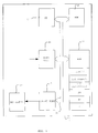
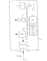
- This device is illustrated in the form of a block diagram and represented by the general reference number 10. It includes, connected to one another by an address and data bus 16 :
- the RAM 12 has in particular a register in which is stored the "initial sequence" made up of at most 64 numbers which can assume 67 different values and which may represent characters or symbols. These numbers are made up of seven binary symbols, none of which include more than four consecutive binary symbols with the same logic state, the first three of which are not in the same logic state and the last three of which are not in the same logic state.
- the RAM 12 in addition has seven registers storing seven groups of variables described below, i , n (i), Sum (i), DoubleSum(i), seq transmitted, R0 and R1.
- the ROM 13 is adapted to store the operating program of the central processing unit 11.
- the central processing unit 11 is adapted to use the flow diagram described in Figure 3.
- the modulator 17 modulates a predetermined physical quantity as a function of an electrical signal.
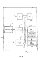
- the physical quantity can be the optical reflectance of a support, as illustrated in Figures 6 and 7, an electrical or optical signal travelling through a network, as illustrated in Figures 8a and 8b, or an acoustic, optical or electromagnetic signal, as illustrated in Figures 9a and 9b.
- Figure 2 is a representation of a total transmitted sequence resulting from the implementation of an "encoding" phase described with reference to Figure 3. Between a start delimiter (or character) 21 and an end delimiter 22, this total transmitted sequence includes, successively, the numbers of the initial sequence to be transferred 20 and two coherence numbers or redundancies R0 and R1.
- the start delimiter 21 and stop delimiter 22 serve to indicate the ends of a message to a means of reading this message. They are of a type known to experts.
- the coherence numbers R0 and R1 are calculated according to the method described with reference to Figure 3, which gives a flow diagram of a program generating coherence numbers relating to the initial sequence to be transferred.
- the coherence numbers R0 and R1 are chosen so that two predetermined "coherence check" combinations applied to the total transmitted sequence each give a predetermined modulo 67 value.
- the coherence numbers R0 and R1 are chosen here so that on the one hand the sum, modulo 67, of all the numbers in the total transmitted sequence is nil (0 thus being the predetermined value corresponding to the second combination).
- R0 and R1 are also chosen so that the sum, modulo 67, of the numbers of the total transmitted sequence each multiplied by a "position" number is nil (0 thus being the predetermined value corresponding to the first combination).
- the position number of each number in the total transmitted sequence is equal to a power of two whose exponent is the position of the said number in the total transmitted sequence, starting from the last (R1) and assigning to it the exponent 0.
- the central processing unit 11 effects the resolution of the two-equation system resulting from these rules.
- the total transmitted sequence follows a "transfer” phase in the course of which it modulates a predetermined physical quantity, which is transferred and demodulated to form a total received sequence in which any "transmission” errors are searched for during a "decoding" phase.
- the decoding phase consists of applying the encoding phase combinations to the numbers in the total received sequence and, where the results of the said combinations are not equal to the said predetermined values corresponding to the said modulo 67 combinations, deducing therefrom that a transmission error has occurred and correcting it.
- the said division necessarily gives as a result a power of 2, the exponent of this power giving the position of the erroneous number, starting from R0, and going up through the total received sequence.
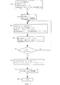
- Figure 3 sets out in detail a flow diagram for a program generating coherence numbers relating to the data to be transferred according to the method described succinctly above. It is applied in particular to bar codes using an alphabet of fewer than 67 characters such that the character juxtapositions include, neither between themselves nor within themselves, sequences of more than four identical binary symbols. For applications not requiring such characteristics, the use of columns 1 and 5 in Table 1 will not be necessary.
- the operation 301 consists of initialising the device according to the invention, more particularly by resetting to zero the variables i , Sum and DoubleSum in the registers of the RAM 12 and of entering in the RAM 12 the data to be transferred received by the central processing unit 11 through the input port 14.
- the operation 302 consists of entering in the RAM 12, in the seq transmitted register, the binary word corresponding to the start delimiter 21, defined in the eighteenth line of Table 1.
- the following operation, marked 303 consists of reading the first available character in the RAM 12 whose number is i , starting from 0, and reading in Table 1, columns 2 and 6, the number n (i) associated with the said character.
- the integer n (i) is between 0 and 66.
- the next operation 304 consists of entering in the same "seq transmitted" register as the start delimiter, following what is already stored there, the binary word corresponding to the integer n (i) which has just undergone operation 303, which binary word is given in columns 1 and 5 of Table 1.
- the operation 306 also consists of storing, after the binary words in the initial sequence and in the seq transmitted register, the two binary words corresponding, with the use of Table 1, to the two coherence numbers R0 and R1, in order to form a "total transmitted sequence".
- the operation 307 stores, after these two coherence numbers and still in the seq transmitted register, a binary word corresponding to an end delimiter 22, given in the fifteenth line of Table 1.
- the operations 302 to 307 constitute the "encoding" phase of the initial sequence in a total transmitted sequence.
- the operation 308 consists of transferring the total transmitted sequence by transferring, in the order of storage in the seq transmitted register, the data present in the latter, to the modulator 17, through the output port 15.
- the modulator 17 then modulates a predetermined physical quantity by the binary data representing the total transmitted sequence.
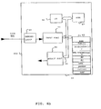
- the binary words of the total transmitted sequence are received in the form of a total "received" sequence by a reception device illustrated in Figure 4, and are processed according to the method of the invention.
- the error detection and correction process is presented with reference to Figures 5a, 5b and 5c, according to the two aspects of the invention.
- the RAM 42 has in particular a register in which is stored the total received sequence currently being processed, as well as ten registers storing ten groups of variables described below, Sum, Doublesum, i , position, n, table, total and current.
- the ROM 43 is adapted to store the operating program of the device and of the central processing unit 41 so that the central processing unit 41 is adapted to implement all the operations set out in the flow chart in Figure 5. It also includes the tables as described in the attached documents.
- the modulator 47 modulates a predetermined physical quantity as a function of an electrical signal issuing from the output port 45 and representing binary data.
- the physical quantity can be the optical reflectance of a support, as illustrated in Figures 6 and 7, an electrical or optical signal travelling through a network, as illustrated in Figures 8a and 8b, or an acoustic, optical or electromagnetic signal, as illustrated in Figures 9a and 9b.
- the demodulator 48 transmits an electrical signal representing binary data to the input port 44, as a function of the physical quantity modulated by the modulator 17.
- the second aspect of the invention applies to the detection and correction of the errors which have occurred owing to the addition or subtraction of one or more binary symbols during the transfer of a "total transmitted" sequence of numbers each representing a number N of binary symbols modulating a predetermined physical quantity, the said total transmitted sequence including at least two "coherence" numbers adapted, according to a "location and evaluation” process, to allow the rectification of any error.
- location and evaluation process means any process allowing the detection and correction of a transmission error consisting of the replacement of a number represented by N binary symbols with an erroneous number also represented by N binary symbols.
- the method according to the first aspect of the invention constitutes a location and evaluation process.
- the method according to the invention then consists, in a "counting" phase, of counting the number of binary symbols in the total received sequence originating from the demodulation of the physical quantity representing the total transmitted sequence and,
- the object of the invention is also a method for detecting and correcting any error in the transmission of a "total transmitted" sequence of fewer than 67 numbers each represented by 7 binary symbols modulating a predetermined physical quantity, the said total transmitted sequence including at least two "coherence” numbers according to the first aspect of the invention, characterised in that, in a "counting" phase, it consists of counting the number of binary symbols in the total received sequence originating from the demodulation of the physical quantity representing the total transmitted sequence and,
- Counting-down of the binary symbols received makes it possible to know whether one, two or more binary symbols have been added to or subtracted from the total transmitted sequence by the transfer.
- the counting-down can give the following results :
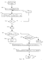
- the device demodulates the physical quantity into binary data and extracts the start delimiter 21.
- the operation 502 consists of demodulating the predetermined physical quantity into binary data.
- the operation 503 consists of adding, in the total register, to the value of the total variable, the number of binary symbols of the character being read, modulo 7.
- Test 504 checks, on the one hand, whether at least five consecutive binary symbols are nil and, on the other hand, whether the last group of seven binary symbols whose last symbol is not nil, is the binary word associated with the end delimiter (see fifteenth line of table 1, column 1 : 0100101). If at least one of these conditions is not fulfilled, the central processing unit 41 returns to the operation 503, effected on the following character. If test 504 is positive, operation 505 consists of extracting the end delimiter and the binary symbols following it and subtracting the number of these binary symbols and of those of the end delimiter of the total variable.
- the test 506 checks whether the total variable is equal to zero, that is to say whether the total number of binary symbols constituting the total received sequence is a multiple of 7. If the test 506 is positive, the operation 507 ( Figure 5b) is implemented. If not, the operation 518 ( Figure 5c) is implemented.
- the "counting" phase is thus constituted by the operations 503, 504, 505 and 506.
- the "decoding" phase corresponds to the operations 507 to 517 presented below.
- the operation 507 consists of creating a table which includes in each position a septuplet of binary symbols taken in the order in which they were read.
- the table of variables table also includes integers n (i) , n (i) corresponding respectively to the septuplets of binary words from 0 to 66.
- the operation 508 consists of resetting to zero the values of three groups of variables, Sum(i), Doublesum(i) and i, representing the position of a septuplet in the table of variables table.
- the test 510 tests whether the table of variables table has been read in full. If not, the operation 511, which increments the value of i by one unit, precedes the repetition of the operation 509. If the test 510 is positive, the operation 512 assigns the value i to the variable n, n thus being the number of elements in the total received sequence.
- the test 513 checks that DoubleSum(n) and Sum(n) are both nil. If so, the error detection shows that there is no transmission error and the program comes out of error correction and proceeds to use the corrected total received sequence, which use is not described here.
- the test 515 tests whether DoubleSum(n) and Sum(n) are both not nil. If the test 515 gives a negative result, an error message is transmitted by the central processing unit 41, and the latter goes to the operation 532 presented later on. This message means that two transmission errors have occurred but that the device according to the invention cannot correct them.
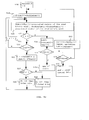
- the operation 518 resets to zero the variables current and i .
- the operation 519 resets to zero the variables i , Sum(i) and DoubleSum(i).
- the following test 521 tests whether the variable i is equal to the variable n. If the result of the test 521 is negative, the test 522 tests whether the variable i is equal to the variable current. If the result of the test 522 is negative, the operation 524 increments the value of i by one unit and the operation 520 calculates the new values of the variables Sum (i) and Doublesum (i), and precedes reimplementation of the test 521.
- the binary words stored in the table table are re-evaluated, that is to say separated from the number of binary data items which have not been read in order to reconstitute a "received" sequence including a good number of multiple-of-7 binary data items.
- the "replacement" phase is constituted here by the operations 527, 528 and 529. After one of the two operations 528 or 529, the operation 520 is re-executed.
- the operation 530 assigns the value -Sum (i), modulo 67, to the variable in the table bearing the number equal to the variable current.
- the test 531 tests whether the variable DoubleSum (i) is equal to the value Sum (i) multiplied by the power of 2 whose exponent is n minus 2 minus current. If the result of the test 531 is positive, error correction is terminated and the operation 525 consists of the use of the table. Otherwise, the test 526 tests whether the value of the variable current is equal to the value of the variable n. If the result of this test is positive, the operation 532 consists of resetting the variables in the RAM to zero and erasing the binary symbols representing the total received sequence.
- the operation 533 effects the operation which is the inverse of the operation 530 and restores the variable in the table which bears the number equal to the variable current to its value originating from the total received sequence, and increments the value of the variable current by one unit, and then goes back to the operation 519.
- the "validation" phase is constituted here by the operations and tests 520, 521, 522, 524, 526, 530, 531 and 533. Error correction is terminated either by the operation 532, it not having been possible to correct the error or errors, or by the operation 514, no error having been detected, or else by the operation 525, the error having been corrected.
- the first aspect of the invention relates to error correction in numbers without modification of the number of binary symbols representing them, and corresponds to the operations 507 to 517 inclusive. Further, the other operations 520 to 535 relate to the same correction extended to the case of the erroneous addition or subtraction of binary symbols.
- Figure 6 depicts a bar code printer incorporating a device according to the invention.
- a bar code printer 600 incorporating the elements presented in Figure 1 and a printing means 601.
- the bar code printer 600 can, for example, be of a known type.
- the printing means can work in particular with a laser, with one or more ink jets, or with a thermal transfer ribbon.
- Figure 7 depicts a bar code reader incorporating a device according to the invention.
- a bar code reader 700 incorporating the elements presented in Figure 4 and a means 701 of optically scanning the bars constituting the said bar code.
- This optical scanning means 701 can include either a photosensitive matrix scanner including several lines of photosensitive dots, or a photosensitive linear scanner including, on a line, a series of photosensitive dots, or alternatively a photosensitive scanner including only a single photosensitive zone, and which is moved in front of the bar code to be scanned.
- bar codes used can be either matrix in form, that is to say comprising a twodimensional network with high-reflectance zones and low-reflectance zones, or linear, that is to say comprising a series of parallel lines of low and high reflectance.
- the modulator 17 translates the electrical pulses arriving from the output port 15 into pulses on a physical quantity conveyed by a cable network 801.
- This physical quantity can, for example, be electrical, difference in potential, amperage, frequency or phase, or else can be optical, light intensity, wavelength, frequency or phase.
- the demodulator 48 translates the variations in the predetermined physical quantity into binary symbols.
- Figures 9a and 9b depict, respectively, a transmitter and receiver for wireless transmission incorporating a device according to the invention.
- a transmitter 900 incorporating all the elements in Figure 1, including a modulator 901 connected to the output port 15, and, in Figure 9b, a receiver 902 incorporating all the elements in Figure 4, including a demodulator 48 connected to the input port 44.
- the modulator 901 can, for example, transmit an electromagnetic signal, a light signal, or alternatively an acoustic signal.
- the demodulator 48 translates the variations in the predetermined physical quantity into binary symbols.
- the second aspect of the invention applies to all the decoding and error detection and correction methods, also referred to above as location and evaluation processes, which are at present limited to the modification of numbers without modification of the number of their constituent binary symbols.
Landscapes
- Physics & Mathematics (AREA)
- Probability & Statistics with Applications (AREA)
- Engineering & Computer Science (AREA)
- Theoretical Computer Science (AREA)
- Detection And Prevention Of Errors In Transmission (AREA)
- Error Detection And Correction (AREA)
- Detection And Correction Of Errors (AREA)
Applications Claiming Priority (3)
| Application Number | Priority Date | Filing Date | Title |
|---|---|---|---|
| FR9513219 | 1995-11-08 | ||
| FR9513219A FR2740925A1 (fr) | 1995-11-08 | 1995-11-08 | Procede et dispositif de detection et de correction d'une eventuelle erreur dans une suite de nombres |
| US08/742,582 US5905739A (en) | 1995-11-08 | 1996-10-28 | Method and device for detecting and correcting any error in a sequence of numbers |
Publications (2)
| Publication Number | Publication Date |
|---|---|
| EP0773628A1 true EP0773628A1 (de) | 1997-05-14 |
| EP0773628B1 EP0773628B1 (de) | 2005-10-12 |
Family
ID=26232321
Family Applications (1)
| Application Number | Title | Priority Date | Filing Date |
|---|---|---|---|
| EP96402261A Expired - Lifetime EP0773628B1 (de) | 1995-11-08 | 1996-10-24 | System und Verfahren zur Erkennung und Korrektur eines beliebiges Fehlers in einer Reihe von Nummern |
Country Status (4)
| Country | Link |
|---|---|
| US (1) | US5905739A (de) |
| EP (1) | EP0773628B1 (de) |
| JP (1) | JP3754772B2 (de) |
| FR (1) | FR2740925A1 (de) |
Cited By (2)
| Publication number | Priority date | Publication date | Assignee | Title |
|---|---|---|---|---|
| FR2764751A1 (fr) * | 1997-06-13 | 1998-12-18 | Canon Kk | Dispositif et procede de decodage d'informations codees |
| US6438112B1 (en) | 1997-06-13 | 2002-08-20 | Canon Kabushiki Kaisha | Device and method for coding information and device and method for decoding coded information |
Families Citing this family (16)
| Publication number | Priority date | Publication date | Assignee | Title |
|---|---|---|---|---|
| US6356925B1 (en) * | 1999-03-16 | 2002-03-12 | International Business Machines Corporation | Check digit method and system for detection of transposition errors |
| FI107675B (fi) * | 1999-07-05 | 2001-09-14 | Nokia Networks Oy | Menetelmä käyttäjälle osoitetun informaation tunnistamiseksi kommunikaatiojärjestelmässä ja kommunikaatiojärjestelmä |
| FR2815199B1 (fr) | 2000-10-10 | 2003-01-17 | Canon Kk | Procedes de turbocodage circulaire de grande distance minimale, et systemes pour leur mise en oeuvre |
| FR2837331B1 (fr) * | 2002-03-13 | 2004-06-18 | Canon Kk | Procede d'entrelacement d'une sequence binaire |
| FR2845220B1 (fr) * | 2002-09-30 | 2004-12-17 | Canon Kk | Procedes et dispositifs pour le decodage des codes de geometrie algebrique a un point |
| FR2849514A1 (fr) * | 2002-12-26 | 2004-07-02 | Canon Kk | Code de geometrie algebrique adapte aux erreurs en rafale |
| FR2853976B1 (fr) * | 2003-04-16 | 2005-06-03 | Canon Kk | Codage d'informations par code de geometrie algebrique offrant deux options de decodage |
| FR2858141A1 (fr) * | 2003-07-21 | 2005-01-28 | Canon Kk | Codage d'informations par codes de reed-solomon raccourcis |
| FR2860360B1 (fr) * | 2003-09-29 | 2005-12-09 | Canon Kk | Dispositif de codage /decodage utilisant un codeur/decodeur de reed-solomon |
| FR2863794B1 (fr) * | 2003-12-16 | 2006-03-03 | Canon Kk | Procedes et dispositifs de localisation d'erreurs pour les codes de geometrie algebrique |
| FR2865083B1 (fr) * | 2004-01-13 | 2006-04-07 | Canon Kk | Decodage pour code de geometrie algebrique associe a un produit fibre. |
| FR2866998B1 (fr) * | 2004-02-27 | 2006-05-19 | Canon Kk | Decodage et correction d'erreurs pour codes de geometrie algebrique |
| FR2867925B1 (fr) * | 2004-03-22 | 2006-05-19 | Canon Kk | Codage de canal adapte aux erreurs rafale |
| FR2873518B1 (fr) * | 2004-07-22 | 2008-12-19 | Canon Kk | Procede de codage et de decodage d'une sequence de mots, signal, codeur, decodeur, programmes d'ordinateur et moyens de stockage correspondants |
| US7433427B2 (en) * | 2004-11-29 | 2008-10-07 | Hewlett-Packard Development Company, L.P. | Enhanced denoising system utilizing incremental parsing |
| FR2880218B1 (fr) * | 2004-12-23 | 2007-02-16 | Canon Kk | Procede de decodage pour codes de geometrie algebrique et dispositif associe |
Citations (3)
| Publication number | Priority date | Publication date | Assignee | Title |
|---|---|---|---|---|
| US4013997A (en) * | 1975-11-17 | 1977-03-22 | Recognition Equipment Incorporated | Error detection/correction system |
| EP0405099A2 (de) * | 1989-06-23 | 1991-01-02 | International Business Machines Corporation | Verfahren und Gerät mit Block-Kode-kodierter Fehlerkorrektur |
| EP0667592A1 (de) * | 1994-01-28 | 1995-08-16 | Canon Inc. | Verfahren zur Kodierung von balkenkodierten Informationen, Verfahren und Vorrichtung zum Lesen derselben |
Family Cites Families (5)
| Publication number | Priority date | Publication date | Assignee | Title |
|---|---|---|---|---|
| GB2132393B (en) * | 1982-12-17 | 1986-05-14 | Sony Corp | Methods and apparatus for correcting errors in binary data |
| US4794239A (en) * | 1987-10-13 | 1988-12-27 | Intermec Corporation | Multitrack bar code and associated decoding method |
| US5373513A (en) * | 1991-08-16 | 1994-12-13 | Eastman Kodak Company | Shift correction code system for correcting additive errors and synchronization slips |
| US5479515A (en) * | 1994-05-11 | 1995-12-26 | Welch Allyn, Inc. | One-dimensional bar code symbology and method of using same |
| US5619027A (en) * | 1995-05-04 | 1997-04-08 | Intermec Corporation | Single width bar code symbology with full character set utilizing robust start/stop characters and error detection scheme |
-
1995
- 1995-11-08 FR FR9513219A patent/FR2740925A1/fr not_active Withdrawn
-
1996
- 1996-10-24 EP EP96402261A patent/EP0773628B1/de not_active Expired - Lifetime
- 1996-10-28 US US08/742,582 patent/US5905739A/en not_active Expired - Lifetime
- 1996-11-08 JP JP29655896A patent/JP3754772B2/ja not_active Expired - Fee Related
Patent Citations (3)
| Publication number | Priority date | Publication date | Assignee | Title |
|---|---|---|---|---|
| US4013997A (en) * | 1975-11-17 | 1977-03-22 | Recognition Equipment Incorporated | Error detection/correction system |
| EP0405099A2 (de) * | 1989-06-23 | 1991-01-02 | International Business Machines Corporation | Verfahren und Gerät mit Block-Kode-kodierter Fehlerkorrektur |
| EP0667592A1 (de) * | 1994-01-28 | 1995-08-16 | Canon Inc. | Verfahren zur Kodierung von balkenkodierten Informationen, Verfahren und Vorrichtung zum Lesen derselben |
Cited By (2)
| Publication number | Priority date | Publication date | Assignee | Title |
|---|---|---|---|---|
| FR2764751A1 (fr) * | 1997-06-13 | 1998-12-18 | Canon Kk | Dispositif et procede de decodage d'informations codees |
| US6438112B1 (en) | 1997-06-13 | 2002-08-20 | Canon Kabushiki Kaisha | Device and method for coding information and device and method for decoding coded information |
Also Published As
| Publication number | Publication date |
|---|---|
| US5905739A (en) | 1999-05-18 |
| JP3754772B2 (ja) | 2006-03-15 |
| FR2740925A1 (fr) | 1997-05-09 |
| JPH09214359A (ja) | 1997-08-15 |
| EP0773628B1 (de) | 2005-10-12 |
Similar Documents
| Publication | Publication Date | Title |
|---|---|---|
| US5905739A (en) | Method and device for detecting and correcting any error in a sequence of numbers | |
| KR960706146A (ko) | 바코드 기호표시법을 이용한 16비트 및 수치데이타 수집장치 및 방법(Apparatus and method for 16-bit and numeric data collection using bar code symbalogies) | |
| US4504948A (en) | Syndrome processing unit for multibyte error correcting systems | |
| PT2136473E (pt) | Método de recuperação de pacote perdido para protocolos de transmissão de pacote | |
| RU2110148C1 (ru) | Способ кодирования и декодирования данных для системы радиовещательной передачи цифровых сообщений | |
| EP1434132A1 (de) | Ein algebraisch-geometrischer Code angepasst für Fehlerhäufungen | |
| US5070504A (en) | Method and apparatus for providing error correction to symbol level codes | |
| US4691319A (en) | Method and system for detecting a predetermined number of unidirectional errors | |
| GB1105583A (en) | Error detection and/or correction of digital information | |
| JPS6316929B2 (de) | ||
| US3544963A (en) | Random and burst error-correcting arrangement | |
| US3588819A (en) | Double-character erasure correcting system | |
| US5034742A (en) | Message compression encoder and encoding method for a communication channel | |
| GB2248751A (en) | Error detection coding system | |
| EP0291961B1 (de) | Verfahren und Gerät zur Dekodierung von blockkodierten Daten, beeinträchtigt durch Ersatz, Einfügungen und Verlust von Symbolen | |
| Borysenko et al. | Noise-immune Transfer of Decimal Data with Protection Based on Permutations | |
| WO2000007338A1 (en) | Replacement of special characters in a data stream | |
| EP0408362A2 (de) | Kodeverarbeitungsgerät zur Fehlererkennung | |
| EP0851621B1 (de) | Kodierte Modulation für Konstellationen, welche weniger Bits pro Symbol haben, als vom Kodierungsschema verlangt wird | |
| SU985959A1 (ru) | Декодер итеративного кода | |
| Ellas | Coding and information theory | |
| KUHN | ERROR CORRECTING CODES PAPER OUTLINE | |
| EP0164027A2 (de) | Verfahren und Vorrichtung zur Kodierung digitaler Daten zur Korrektur von ein oder zwei Fehlerdatengruppen | |
| SU1012450A1 (ru) | Декодер двоичного кода | |
| KR100245611B1 (ko) | 단일 에러 감지 회로 및 정정 회로 |
Legal Events
| Date | Code | Title | Description |
|---|---|---|---|
| PUAI | Public reference made under article 153(3) epc to a published international application that has entered the european phase |
Free format text: ORIGINAL CODE: 0009012 |
|
| AK | Designated contracting states |
Kind code of ref document: A1 Designated state(s): DE ES FR GB IT |
|
| 17P | Request for examination filed |
Effective date: 19971017 |
|
| 17Q | First examination report despatched |
Effective date: 20000626 |
|
| GRAP | Despatch of communication of intention to grant a patent |
Free format text: ORIGINAL CODE: EPIDOSNIGR1 |
|
| GRAS | Grant fee paid |
Free format text: ORIGINAL CODE: EPIDOSNIGR3 |
|
| GRAA | (expected) grant |
Free format text: ORIGINAL CODE: 0009210 |
|
| AK | Designated contracting states |
Kind code of ref document: B1 Designated state(s): DE ES FR GB IT |
|
| PG25 | Lapsed in a contracting state [announced via postgrant information from national office to epo] |
Ref country code: IT Free format text: LAPSE BECAUSE OF FAILURE TO SUBMIT A TRANSLATION OF THE DESCRIPTION OR TO PAY THE FEE WITHIN THE PRE;WARNING: LAPSES OF ITALIAN PATENTS WITH EFFECTIVE DATE BEFORE 2007 MAY HAVE OCCURRED AT ANY TIME BEFORE 2007. THE CORRECT EFFECTIVE DATE MAY BE DIFFERENT FROM THE ONE RECORDED.SCRIBED TIME-LIMIT Effective date: 20051012 |
|
| REG | Reference to a national code |
Ref country code: GB Ref legal event code: FG4D |
|
| PG25 | Lapsed in a contracting state [announced via postgrant information from national office to epo] |
Ref country code: ES Free format text: LAPSE BECAUSE OF FAILURE TO SUBMIT A TRANSLATION OF THE DESCRIPTION OR TO PAY THE FEE WITHIN THE PRESCRIBED TIME-LIMIT Effective date: 20060123 |
|
| REF | Corresponds to: |
Ref document number: 69635261 Country of ref document: DE Date of ref document: 20060223 Kind code of ref document: P |
|
| ET | Fr: translation filed | ||
| PLBE | No opposition filed within time limit |
Free format text: ORIGINAL CODE: 0009261 |
|
| STAA | Information on the status of an ep patent application or granted ep patent |
Free format text: STATUS: NO OPPOSITION FILED WITHIN TIME LIMIT |
|
| 26N | No opposition filed |
Effective date: 20060713 |
|
| PGFP | Annual fee paid to national office [announced via postgrant information from national office to epo] |
Ref country code: DE Payment date: 20121031 Year of fee payment: 17 Ref country code: FR Payment date: 20121127 Year of fee payment: 17 |
|
| PGFP | Annual fee paid to national office [announced via postgrant information from national office to epo] |
Ref country code: GB Payment date: 20121016 Year of fee payment: 17 |
|
| GBPC | Gb: european patent ceased through non-payment of renewal fee |
Effective date: 20131024 |
|
| PG25 | Lapsed in a contracting state [announced via postgrant information from national office to epo] |
Ref country code: GB Free format text: LAPSE BECAUSE OF NON-PAYMENT OF DUE FEES Effective date: 20131024 |
|
| REG | Reference to a national code |
Ref country code: FR Ref legal event code: ST Effective date: 20140630 |
|
| REG | Reference to a national code |
Ref country code: DE Ref legal event code: R119 Ref document number: 69635261 Country of ref document: DE Effective date: 20140501 |
|
| PG25 | Lapsed in a contracting state [announced via postgrant information from national office to epo] |
Ref country code: FR Free format text: LAPSE BECAUSE OF NON-PAYMENT OF DUE FEES Effective date: 20131031 Ref country code: DE Free format text: LAPSE BECAUSE OF NON-PAYMENT OF DUE FEES Effective date: 20140501 |